实验报告
一 实验要求
二层使用MSTP+VRRP实现破环和冗余。
-
交换机之间trunk使用最少vlan透传原则
-
sw1,sw2之间链路做聚合
-
MSTP name配置为SC
-
MSTP 实例映射为:
instance 1 vlan 21
instance 2 vlan 22 23 100
5.sw1为实例1,0的根,实例2的备份根
-
sw2为实例2的根,实例1,0的备份根
-
所有access接口配置为边缘接口,并配置BPDU保护,同时需要过滤用户收到STP相关报文。
-
sw1为vlanif 21的master,sw2为backup
-
sw2为vlanif 22的master,sw1为backup
10.sw1与sw2的VRRP需监控上行链路,双上行都down时切换网关,抢占延时为20s
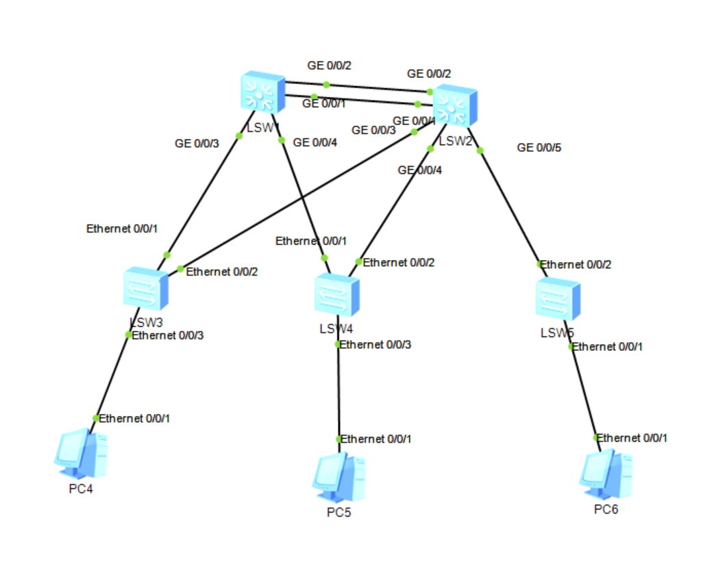
二 实验拓补
三 实验步骤
- 首先配置链路聚合
D-1interface Eth-Trunk 0
sw1-Eth-Trunk0trunkport g0/0/1
sw1-Eth-Trunk0trunkport g0/0/2
sw2-Eth-Trunk0trunkport g0/0/1
sw2-Eth-Trunk0trunkport g0/0/2
- 然后配置vlan和通道
sw1vlan batch 21 to 23
sw1vlan 100
sw2vlan batch 21 to 23
sw2vlan 100
sw1-Eth-Trunk0
sw1-Eth-Trunk0port link-type trunk
sw1-Eth-Trunk0p t a v 100
sw3-Ethernet0/0/1p l t
sw3-Ethernet0/0/1p t a v 100
sw4-Ethernet0/0/1p l t
sw4-Ethernet0/0/1p t a v 21
sw4-Ethernet0/0/2p l t
sw4-Ethernet0/0/2p t a v 22
sw5-Ethernet0/0/2p l t
sw5-Ethernet0/0/2p t a v 23
sw3-Ethernet0/0/3p l a
sw4-Ethernet0/0/3p l a
sw5-Ethernet0/0/3p l a
- 配置MSTP协议和选举主备份根 :
sw1stp enable
sw1stp mode mstp
sw1stp region-configuration
sw1-mst-regionregion-name SC
sw1-mst-regioninstance 1 vlan 21
sw1-mst-regioninstance 2 vlan 22 23 100
sw1stp instance 0 root primary
sw1stp instance 1 root primary
sw1-mst-regionactive region-configuration
sw2stp enable
sw2stp mode mstp
sw2stp region-configuration
sw2-mst-regionregion-name SC
sw2-mst-regioninstance 1 vlan 21
sw2-mst-regioninstance 2 vlan 22 23 100
sw2stp instance 0 root secondary
sw2stp instance 1 root secondary
sw2stp instance 2 root primary
sw2-mst-regionactive region-configuration
4.接口配置为边缘接口,并配置BPDU保护
sw3-Ethernet0/0/3stp edged-port enable
sw3-Ethernet0/0/3stp bpdu-filter enable
sw4-Ethernet0/0/3stp edged-port enable
sw4-Ethernet0/0/3stp bpdu-filter enable
sw5-Ethernet0/0/1stp edged-port enable
sw5-Ethernet0/0/1stp bpdu-filter enable
Vlanif的配置
sw1int Vlanif 21
sw1-Vlanif21ip add 192.168.21.1 24
sw1-Vlanif21int vlan 22
sw1-Vlanif22ip add 192.168.22.1 24
sw1-Vlanif22int vlan 23
sw1-Vlanif23ip add 192.168.23.1 24
sw1-Vlanif23int vlan 100
sw1-Vlanif100ip add 192.168.0.1 24
- .我们假设sw1与sw2的0/0/和0/0/6接口为上行链路 配置监控
sw1-Vlanif21vrrp vrid 1 virtual-ip 192.168.21.254
sw1-Vlanif22vrrp vrid 1 virtual-ip 192.168.22.254
sw1-Vlanif23vrrp vrid 1 virtual-ip 192.168.23.254
sw1-Vlanif22vrrp vrid 1 track interface g0/0/4 reduced 15
sw1-Vlanif21vrrp vrid 1 track interface g0/0/4 reduced 15
sw1-Vlanif23vrrp vrid 1 track interface g0/0/4 reduced 15
Sw2同理
至此