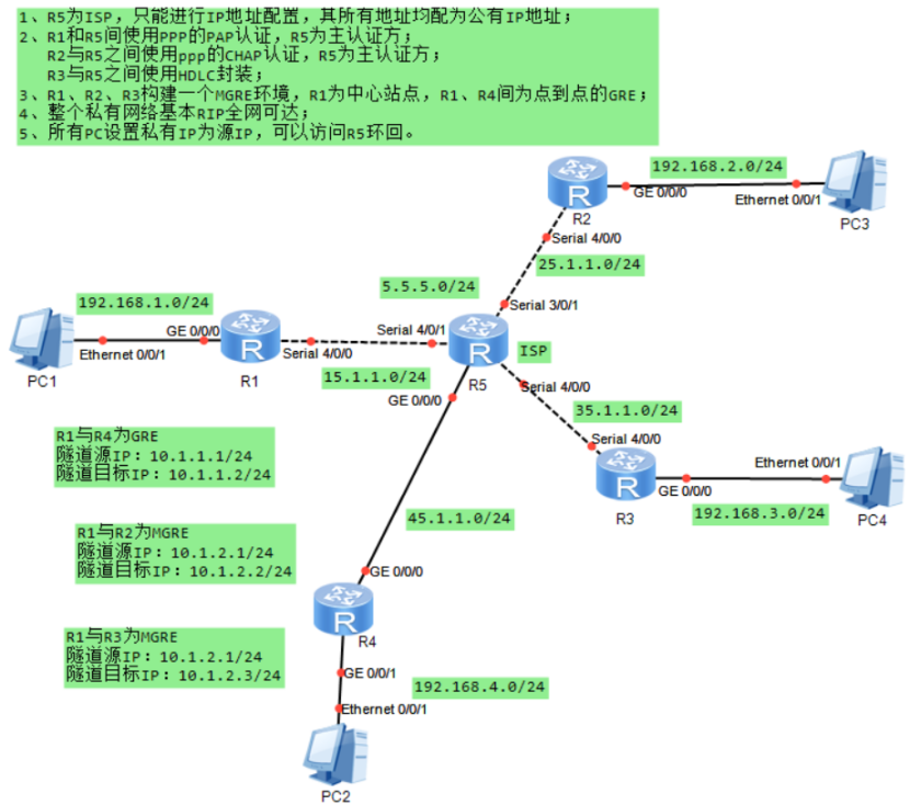
一、实验拓扑
二、实验要求
1、R5为ISP,只能进行I地址配置,其所有地址均配为公有I地址;
2、R1和R5间使用PPP的PAP认证,R5为主认证方
R2与R5之间使用ppp的cHAP认证,R5为主认证方;
R3与R5之间使用HDLC封装;
3、R1、R2、R3构建一个MGRE环境,R1为中心站点,R1、R4间为点到点的GRE;
4、整个私有网络基本RIP全网可达;
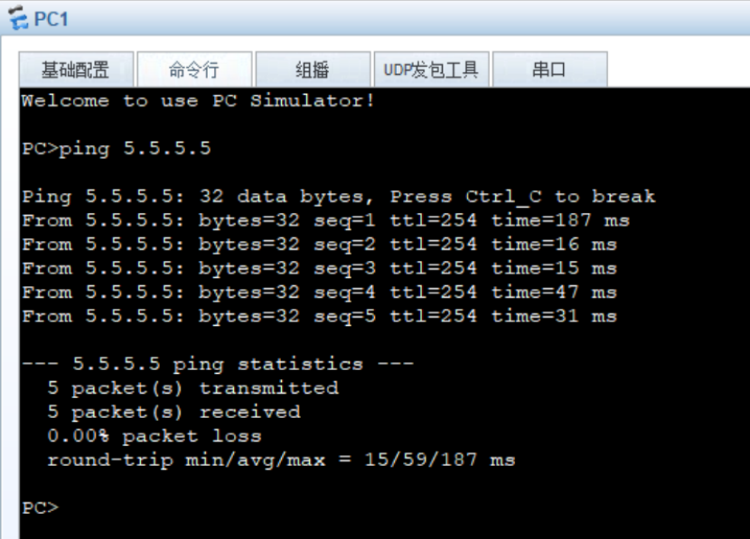
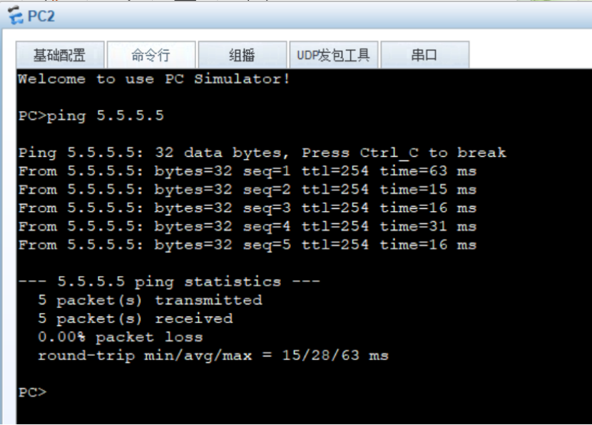
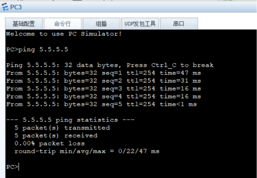
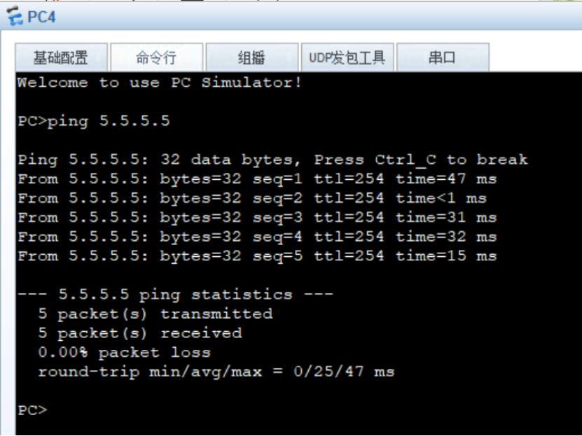
5、所有Pc设置私有IP为源IP,可以访问5环回
三、实验思路
1、配置IP地址
2、配置PAP、CHAP、HDLC封装
3、配置MGRE、GRE
4、配置RIP协议
5、配置NAT
测试和验证
四、实验步骤
1、IP地址配置
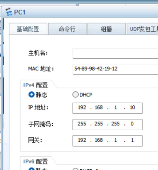
R1int g 0/0/0
R1-GigabitEthernet0/0/0ip add 192.168.1.1 24
R1int Serial 4/0/0
R1-Serial4/0/0ip add 15.1.1.1 24
R2int g0/0/0
R2-GigabitEthernet0/0/0ip add 192.168.2.2 24
R2int Serial 4/0/0
R2-Serial4/0/0ip add 25.1.1.2 24
R3int g 0/0/0
R3-GigabitEthernet0/0/0ip add 192.168.3.3 24
R3int Serial 4/0/0
R3-Serial4/0/0ip add 35.1.1.3 24
R4int g 0/0/0
R4-GigabitEthernet0/0/0ip add 45.1.1.4 24
R4-GigabitEthernet0/0/0int g 0/0/1
R4-GigabitEthernet0/0/1ip add 192.168.4.4 24
R5int Serial 4/0/1
R5-Serial4/0/1ip add 15.1.1.5 24
R5-Serial4/0/1int g 0/0/0
R5-GigabitEthernet0/0/0ip add 45.1.1.5 24
R5int Serial 3/0/1
R5-Serial3/0/1ip add 25.1.1.5 24
R5int Serial 4/0/0
R5-Serial4/0/0ip add 35.1.1.5 24
(2)配置静态ip
R1ip route-static 0.0.0.0 0 15.1.1.5
R2ip route-static 0.0.0.0 0 25.1.1.5
R3ip route-static 0.0.0.0 0 35.1.1.5
R4ip route-static 0.0.0.0 0 45.1.1.5
3、PPP认证(配置PAP、CHAP、HDLC封装)
(1)R1 R5 PAP R5为主认证方
R5aaa
R5-aaalocal-user xxx password cipher xxx111
R5-aaaint s4/0/1
R5-Serial4/0/1ppp authentication-mode pap
R1int s 4/0/0
R1-Serial4/0/0ppp pap local-user xxx password cipher xxx111
(2)R2 R5 CHAP R5为主认证方
R5aaa
R5-aaalocal-user sss password cipher sss222
R5-aaalocal-user sss service-type ppp
R5-aaaint s3/0/1
R5-Serial3/0/1ppp authentication-mode chap
R2int s 4/0/0
R2-Serial4/0/0ppp chap user sss
R2-Serial4/0/0ppp chap password cipher sss222
(3)R3 R5 HDLC
R5aaa
R5-aaalocal-user xsq password cipher xsq789
R5-aaalocal-user xsq service-type ppp
R5int Serial 4/0/0
R5-Serial4/0/0ppp authentication-mode chap
R5-Serial4/0/0link-protocol hdlc
R3int Serial 4/0/0
R3-Serial4/0/0ppp pap local-user xsq password cipher xsq789
R3-Serial4/0/0ppp authentication-mode chap
R3-Serial4/0/0link-protocol hdlc
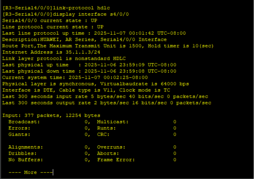
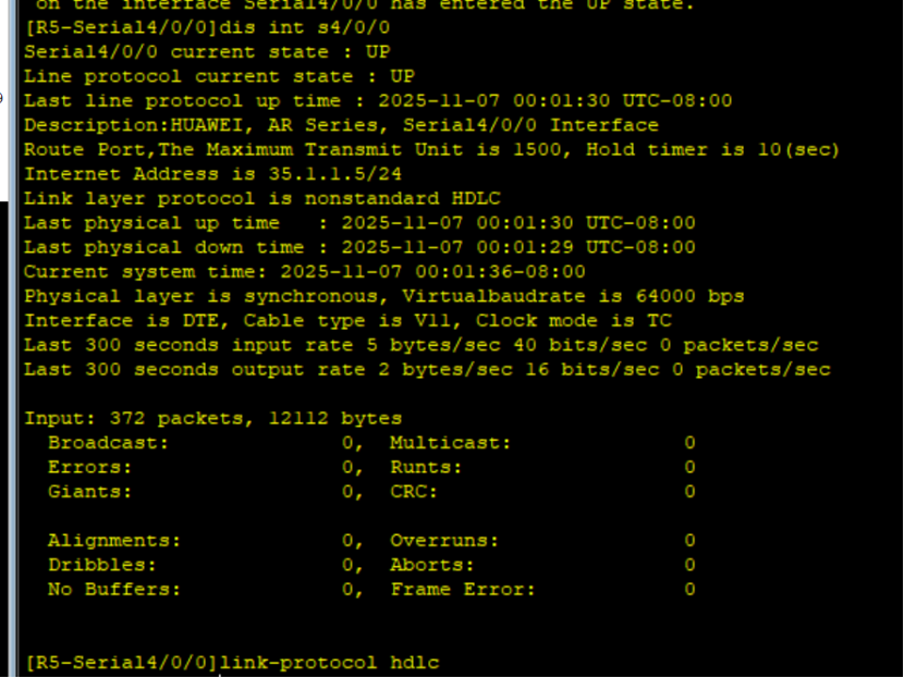
全网通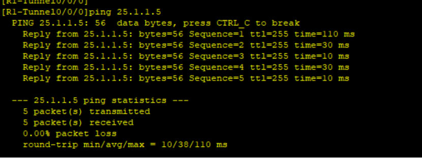

4、配置MGRE、GRE
构建隧道
(1)R2、R3构建一个MGRE环境,R1为中心站点
R1int Tunnel 0/0/0
R1-Tunnel0/0/0ip add 10.1.2.1 24
R1-Tunnel0/0/0tunnel-protocol gre p2mp
R1-Tunnel0/0/0source 15.1.1.1
R1-Tunnel0/0/0nhrp network-id 100
R2int Tunnel 0/0/0
R2-Tunnel0/0/0ip add 10.1.2.2 24
R2-Tunnel0/0/0tunnel-protocol gre p2mp
R2-Tunnel0/0/0source Serial 4/0/0
R2-Tunnel0/0/0nhrp network-id 100
R2-Tunnel0/0/0nhrp entry 10.1.2.1 15.1.1.1 register
R3int Tunnel 0/0/0
R3-Tunnel0/0/0ip add 10.1.2.3 24
R3-Tunnel0/0/0tunnel-protocol gre p2mp
R3-Tunnel0/0/0source Serial 4/0/0
R3-Tunnel0/0/0nhrp entry 10.1.2.1 15.1.1.1 register
(2)R1、R4间为点到点的GRE
R1int Tunnel 0/0/1
R1-Tunnel0/0/1ip add 10.1.1.1 24
R1-Tunnel0/0/1tunnel-protocol gre
R1-Tunnel0/0/1source 15.1.1.1
R1-Tunnel0/0/1destination 45.1.1.4
R4int Tunnel 0/0/1
R4-Tunnel0/0/1ip add 10.1.1.2 24
R4-Tunnel0/0/1tunnel-protocol gre
R4-Tunnel0/0/1source 45.1.1.4
R4-Tunnel0/0/1destination 15.1.1.1
4、配置RIP协议
R1rip 1
R1-rip-1version 2
R1-rip-1undo summary
R1-rip-1network 192.168.1.0
R1-rip-1network 10.0.0.0
R2rip 1
R2-rip-1version 2
R2-rip-1undo summary
R2-rip-1network 192.168.2.0
R2-rip-1network 10.0.0.0
R3rip 1
R3-rip-1version 2
R3-rip-1undo summary
R3-rip-1network 192.168.3.0
R3-rip-1network 10.0.0.0
R4rip 1
R4-rip-1version 2
R4-rip-1undo summary
R4-rip-1network 192.168.4.0
R4-rip-1network 10.0.0.0
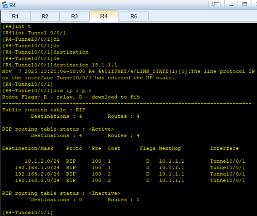
查看rip表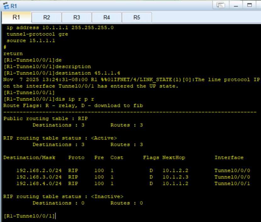
5、配置NAT
R1acl 2000
R1-acl-basic-2000rule 5 permit source 192.168.1.0 0.0.0.255
R1-acl-basic-2000q
R1int Serial 4/0/0
R1-Serial4/0/0nat outbound 2000
R2acl 2000
R2-acl-basic-2000rule 5 permit source 192.168.2.0 0.0.0.255
R2-acl-basic-2000int s 4/0/0
R2-Serial4/0/0nat outbound 2000
R3acl 2000
R3-acl-basic-2000rule 5 permit source 192.168.3.0 0.0.0.255
R3-acl-basic-2000int s4/0/0
R3-Serial4/0/0nat outbound 2000
R4acl 2000
R4-acl-basic-2000rule 5 permit source 192.168.4.0 0.0.0.255
R4-acl-basic-2000int g 0/0/0
R4-GigabitEthernet0/0/0nat outbound 2000
6、测试