注:本文为 "滤波器" 相关译文。
机翻未校。如有内容异常,请看原文。
Difference between Active and Passive Filters?
有源滤波器与无源滤波器的区别?
This article explores the key differences between active and passive filters, detailing their transfer functions, frequency responses, components, circuit configurations, stability, design challenges, approximation methods, and CAD tools for filter simulation and optimization.
本文探讨了有源滤波器与无源滤波器之间的关键差异,详细介绍了它们的传递函数、频率响应、组件、电路配置、稳定性、设计挑战、逼近方法以及用于滤波器仿真和优化的计算机辅助设计(CAD)工具。
Umar Waseem
Last updated on 10 Apr, 2024
Introduction
引言
Filters are fundamental building blocks in various electronic systems, performing the crucial task of selectively passing desired frequencies in a signal while attenuating unwanted ones. This selective processing allows for extracting specific information or protecting sensitive circuits from harmful noise. There exist two main categories of filters: active and passive!
滤波器是各种电子系统中的基本组成部分,其核心功能是选择性地让信号中所需频率通过,同时衰减不需要的频率。这种选择性处理能够提取特定信息,或保护敏感电路免受有害噪声的影响。滤波器主要分为两大类:有源滤波器和无源滤波器!
Curious to know the difference between Active and Passive filters? Passive filters, built with resistors, capacitors, and inductors, leverage the inherent properties of these components to attenuate or pass specific frequencies. Conversely, active filters combine passive components with active elements like operational amplifiers, offering greater control and design flexibility.
想了解有源滤波器与无源滤波器的区别吗?无源滤波器由电阻、电容和电感构成,利用这些组件的固有特性来衰减或让特定频率通过。相反,有源滤波器将无源组件与运算放大器等有源元件相结合,提供了更强的可控性和设计灵活性。
While passive filters excel in simplicity and linearity, active filters provide superior performance, improved signal isolation, and the ability to realize more complex transfer functions. However, this enhanced functionality comes at the cost of increased circuit complexity and power consumption.
无源滤波器在简洁性和线性方面表现出色,而有源滤波器则具有更优异的性能、更好的信号隔离效果,并且能够实现更复杂的传递函数。然而,这种增强的功能是以增加电路复杂性和功耗为代价的。
What are Filters in Electronic Circuits?
电子电路中的滤波器是什么?
Filters in electronic circuits are networks designed to manipulate the frequency components of an input signal selectively. By attenuating, passing, or amplifying specific frequencies, filters shape the amplitude and phase characteristics of the signal to achieve the desired frequency response.
电子电路中的滤波器是一种网络,旨在选择性地操控输入信号的频率成分。通过衰减、通过或放大特定频率,滤波器可调整信号的幅度和相位特性,以实现期望的频率响应。
The French mathematician, Joseph Fourier, discovered that any periodic signal can be represented as a sum of sine and cosine waves. 1 The amplitudes of these waves can be determined by analyzing the signal. This means that any periodic signal can be broken down into a set of sine and cosine waves with specific frequencies. These individual frequencies can be manipulated to change the characteristics of the entire signal. As a result, filters can be described by their effect on different frequency components of a signal.
法国数学家约瑟夫·傅里叶(Joseph Fourier)发现,任何周期信号都可以表示为正弦波和余弦波的总和。1 这些波形的幅度可通过分析信号来确定。这意味着任何周期信号都能分解为一组具有特定频率的正弦波和余弦波。通过操控这些单个频率,可改变整个信号的特性。因此,滤波器的描述可基于其对信号不同频率成分的作用。
Fourier Transform, J. Fourier, 1822
傅里叶变换,J. 傅里叶,1822 年
F ( ω ) = ∫ − ∞ ∞ f ( t ) e − j ω t d t F(\omega) = \int_{-\infty}^{\infty} f(t) e^{-j\omega t} \mathrm{d}t F(ω)=∫−∞∞f(t)e−jωtdt
The primary goal of filters is to remove unwanted frequency components, such as noise or interference while preserving or enhancing the desired signal components. They are crucial in signal processing applications, as they improve signal quality, prevent aliasing, and maintain the signal within the desired frequency range. Filters help maintain signal integrity and extract relevant information from complex signals in various electronic domains, including telecommunications, audio systems, and data acquisition.
滤波器的主要目标是去除噪声或干扰等不需要的频率成分,同时保留或增强所需的信号成分。在信号处理应用中,滤波器至关重要,它们能提高信号质量、防止混叠,并将信号保持在期望的频率范围内。在电信、音频系统和数据采集等多个电子领域,滤波器有助于维持信号完整性,并从复杂信号中提取相关信息。
Types of Filters
滤波器的类型
Filters can be broadly categorized into two main types: passive filters and active filters. However, within these, there are fundamental types based on frequency response. The most common types of filters are low-pass, high-pass, band-pass, and band-reject (or notch) filters. Let's see the difference between active and passive filters.
滤波器大致可分为两大类:无源滤波器和有源滤波器。此外,根据频率响应,它们还可细分为基本类型。最常见的滤波器类型包括低通滤波器、高通滤波器、带通滤波器和带阻滤波器(或陷波滤波器)。下面我们来详细了解有源滤波器与无源滤波器的区别。
Active Filters
有源滤波器
Active filters combine passive components with active elements, primarily operational amplifiers (Op-amp) and transistors. The inclusion of active components enables more complex filter designs, providing several advantages over passive filters. Active filters offer higher selectivity, better signal isolation, and the ability to realize more precise transfer functions. 2 They can also introduce gain to compensate for signal attenuation caused by the passive components. Nevertheless, active filters require a power supply and may introduce noise and distortion due to the presence of active components.
有源滤波器将无源组件与有源元件相结合,主要包括运算放大器(Op-amp)和晶体管。有源元件的加入使得滤波器设计更加复杂,相比无源滤波器具有多项优势。有源滤波器具有更高的选择性、更好的信号隔离效果,并且能够实现更精确的传递函数。2 它们还可以引入增益,以补偿无源组件造成的信号衰减。然而,有源滤波器需要电源供电,且由于有源元件的存在,可能会引入噪声和失真。
Passive Filters
无源滤波器
Passive filters rely solely on passive components - resistors ®, capacitors ©, and inductors (L) - to manipulate signal frequencies. These components offer inherent properties that affect how they interact with current at different frequencies. Passive filters are renowned for their simplicity, linearity, and ability to handle high power levels. However, passive filters face limitations in terms of gain, selectivity, and flexibility in shaping the frequency response.
无源滤波器仅依靠无源组件------电阻(R)、电容(C)和电感(L)------来操控信号频率。这些组件具有固有特性,会影响它们在不同频率下与电流的相互作用。无源滤波器以其简洁性、线性特性和高功率处理能力而闻名。然而,无源滤波器在增益、选择性和频率响应调整的灵活性方面存在局限性。
Transfer Functions and Frequency Response
传递函数与频率响应
The mathematical representation of filters relies heavily on transfer functions and frequency response. The transfer function, H ( s ) H(s) H(s) in the s-domain or H ( z ) H(z) H(z) in the Z-domain, describes the relationship between the input and output signals of a filter in terms of gain and phase characteristics as a function of frequency. The frequency response, obtained by evaluating the transfer function at different frequencies, provides insights into the filter's passband, stopband, and transition band behavior.
滤波器的数学表示在很大程度上依赖于传递函数和频率响应。传递函数(s 域中的 H ( s ) H(s) H(s) 或 Z 域中的 H ( z ) H(z) H(z))描述了滤波器输入信号与输出信号之间的关系,体现为增益和相位特性随频率的变化。频率响应通过在不同频率下求解传递函数得到,可反映滤波器的通带、阻带和过渡带特性。
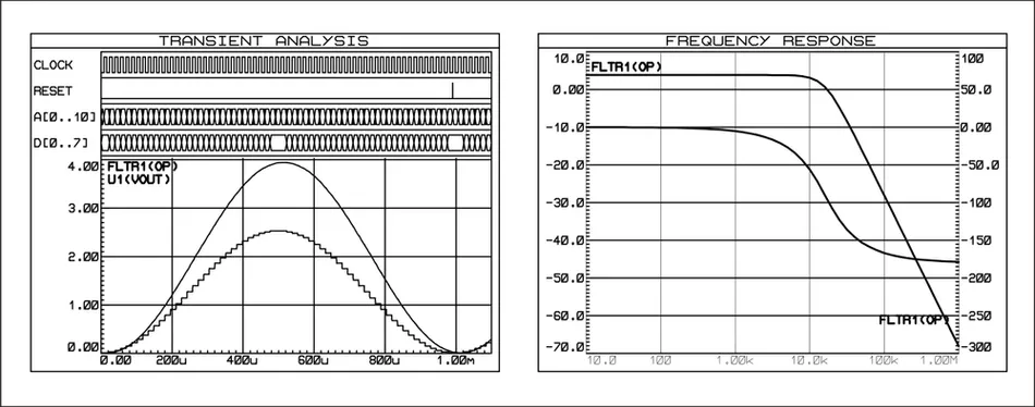
Graphs of signals (Transient Analysis, Frequency Response)
信号曲线图(瞬态分析、频率响应)
Filter Order and Roll-Off Rate
滤波器阶数与滚降速率
Filter order, defined as the highest degree of the denominator polynomial in the transfer function, plays a significant role in filter design. Higher-order filters offer steeper roll-off rates and better selectivity, allowing for sharper transitions between the passband and stopband. However, increasing the filter order also leads to increased complexity and potential stability issues. The roll-off rate, measured in decibels per octave (dB/octave) or decibels per decade (dB/decade), quantifies how quickly the filter's response attenuates in the stopband. All first-order filters have a 20 dB/decade roll-off. The same roll-off can also be specified as 6 dB/octave. An octave is a term borrowed from music and represents a doubling of frequency. 3
滤波器阶数定义为传递函数分母多项式的最高次数,在滤波器设计中起着重要作用。高阶滤波器具有更陡峭的滚降速率和更好的选择性,能够实现通带和阻带之间更尖锐的过渡。然而,增加滤波器阶数也会导致复杂性增加,并可能引发稳定性问题。滚降速率以每倍频程分贝(dB/octave)或每十倍频程分贝(dB/decade)为单位,用于量化滤波器在阻带中的响应衰减速度。所有一阶滤波器的滚降速率均为 20 dB/十倍频程,也可表示为 6 dB/倍频程。"倍频程"一词源自音乐,指频率翻倍。3
Cutoff Frequency and Passband/Stopband
截止频率与通带/阻带
The cutoff frequency is a critical parameter that separates the passband and stopband of a filter. In a low-pass filter, frequencies below the cutoff are passed, while those above are attenuated. Conversely, in a high-pass filter, frequencies above the cutoff are passed, and those below are attenuated. Band-pass and band-stop filters have two cutoff frequencies, defining the range of frequencies that are passed or attenuated, respectively.
截止频率是区分滤波器通带和阻带的关键参数。在低通滤波器中,截止频率以下的频率可以通过,而高于截止频率的频率会被衰减。相反,在高通滤波器中,截止频率以上的频率可以通过,而低于截止频率的频率会被衰减。带通滤波器和带阻滤波器有两个截止频率,分别定义了可通过或需衰减的频率范围。
Transfer Functions for Common Filter Types
常见滤波器类型的传递函数
Transfer functions for common filter types have specific forms that reflect their frequency-selective behavior.
常见滤波器类型的传递函数具有特定形式,反映了它们的频率选择特性。
For example:
例如:
-
First-order low-pass filter:
一阶低通滤波器:
H ( s ) = 1 1 + s ω 0 H(s) = \frac{1}{1 + \frac{s}{\omega_{0}}} H(s)=1+ω0s1where ω 0 \omega_{0} ω0 is the cutoff frequency.
其中 ω 0 \omega_{0} ω0 为截止频率。
-
Second-order band-pass filter or resonant RLC circuit:
二阶带通滤波器或谐振 RLC 电路:
H ( s ) = s Q s 2 + s Q + ω 0 2 H(s) = \frac{\frac{s}{Q}}{s^{2} + \frac{s}{Q} + \omega_{0}^{2}} H(s)=s2+Qs+ω02Qswhere Q Q Q is the quality factor, and ω 0 \omega_{0} ω0 is the center frequency.
其中 Q Q Q 为品质因数, ω 0 \omega_{0} ω0 为中心频率。
-
Second-order notch filter:
二阶陷波滤波器:
H ( s ) = s 2 + ω 0 2 s 2 + s ( ω 0 Q ) + ω 0 2 H(s) = \frac{s^{2} + \omega_{0}^{2}}{s^{2} + s\left(\frac{\omega_{0}}{Q}\right) + \omega_{0}^{2}} H(s)=s2+s(Qω0)+ω02s2+ω02where Q Q Q is the quality factor, and ω 0 \omega_{0} ω0 is the notch frequency.
其中 Q Q Q 为品质因数, ω 0 \omega_{0} ω0 为陷波频率。
These transfer functions provide a mathematical foundation for analyzing and designing filters to achieve the desired frequency response characteristics. This enables engineers to select the appropriate filter type and parameters for their specific applications.
这些传递函数为分析和设计滤波器以实现期望的频率响应特性提供了数学基础。这使工程师能够为特定应用选择合适的滤波器类型和参数。
Components Used in Active Filters
有源滤波器使用的组件
Active filters incorporate active components alongside passive ones. They combine passive components with active elements , primarily operational amplifiers (Op-amp) and transistors . Here's a breakdown of the key players in active filters:
有源滤波器结合了无源组件和有源元件,主要包括运算放大器(Op-amp)和晶体管。以下是有源滤波器中的关键组件详解:
Operational Amplifiers (Op-amps) are high-gain differential amplifiers that amplify the difference between two input voltages. They provide features like high input impedance, low output impedance, and controllable gain.
运算放大器(Op-amp)是高增益差分放大器,用于放大两个输入电压之间的差值。它们具有高输入阻抗、低输出阻抗和可控增益等特性。
Transistors can achieve a limited filtering function in basic active filter circuits, requiring fewer components than an op-amp-based design. Some transistor types may operate effectively at lower voltages than readily available op-amps, making them suitable for battery-powered or low-power circuits.
在基本的有源滤波器电路中,晶体管可实现有限的滤波功能,相比基于运算放大器的设计,所需组件更少。某些类型的晶体管可以在比现成运算放大器更低的电压下有效工作,因此适用于电池供电或低功耗电路。
Active Filter: Circuit Configurations and Transfer Functions
有源滤波器:电路配置与传递函数
Active filters can be designed using various circuit configurations, each with its own transfer function and frequency response characteristics. The three most common circuit configurations are:
有源滤波器可通过多种电路配置实现,每种配置都有其独特的传递函数和频率响应特性。三种最常见的电路配置如下:
Sallen-Key Configuration
萨伦-基(Sallen-Key)配置
-
Second-order filter topology using two op-amps, two resistors, and two capacitors.
二阶滤波器拓扑结构,使用两个运算放大器、两个电阻和两个电容。
-
Known for simplicity, low component count, and good performance in low-Q applications.
以简洁性、低组件数量和在低 Q 值应用中的良好性能而闻名。
-
Transfer function of a Sallen-Key low-pass filter:
萨伦-基低通滤波器的传递函数:
H ( s ) = 1 1 + ( R 1 C 1 + R 2 C 2 ) s + ( R 1 R 2 C 1 C 2 ) s 2 H(s) = \frac{1}{1 + (R_1 C_1 + R_2 C_2) s + (R_1 R_2 C_1 C_2) s^2} H(s)=1+(R1C1+R2C2)s+(R1R2C1C2)s21 -
Cutoff frequency:
截止频率:
ω 0 = 1 R 1 R 2 C 1 C 2 \omega_{0} = \frac{1}{\sqrt{R_1 R_2 C_1 C_2}} ω0=R1R2C1C2 1(标准萨伦-基截止频率公式) -
Quality factor:
品质因数:
Q = R 1 R 2 C 1 C 2 R 1 C 1 + R 2 C 2 Q = \frac{\sqrt{R_1 R_2 C_1 C_2}}{R_1 C_1 + R_2 C_2} Q=R1C1+R2C2R1R2C1C2 (标准萨伦-基品质因数公式)

Sallen-Key low-pass filter schematic
萨伦-基低通滤波器原理图
Multiple Feedback (MFB) Configuration
多重反馈(MFB)配置
-
Second-order filter topology using one op-amp, three resistors, and two capacitors.
二阶滤波器拓扑结构,使用一个运算放大器、三个电阻和两个电容。
-
Offers good performance in high-Q applications and provides a non-inverting bandpass output.
在高 Q 值应用中表现出色,并提供同相带通输出。
-
Transfer function of an MFB bandpass filter:
多重反馈带通滤波器的传递函数:
H ( s ) = − R 2 C 2 s ( R 1 R 3 C 1 C 2 ) s 2 + ( R 1 C 1 + R 3 C 2 + R 2 C 2 ) s + 1 H(s) = \frac{-R_{2} C_{2} s}{(R_{1} R_{3} C_{1} C_{2}) s^{2} + (R_{1} C_{1} + R_{3} C_{2} + R_{2} C_{2}) s + 1} H(s)=(R1R3C1C2)s2+(R1C1+R3C2+R2C2)s+1−R2C2s -
Cutoff frequency:
截止频率:
ω 0 = 1 R 1 R 3 C 1 C 2 \omega_{0} = \frac{1}{\sqrt{R_{1} R_{3} C_{1} C_{2}}} ω0=R1R3C1C2 1 -
Quality factor:
品质因数:
Q = R 2 R 1 C 2 R 1 C 1 + R 3 C 2 + R 2 C 2 Q = \frac{R_{2} \sqrt{R_{1} C_{2}}}{R_{1} C_{1} + R_{3} C_{2} + R_{2} C_{2}} Q=R1C1+R3C2+R2C2R2R1C2
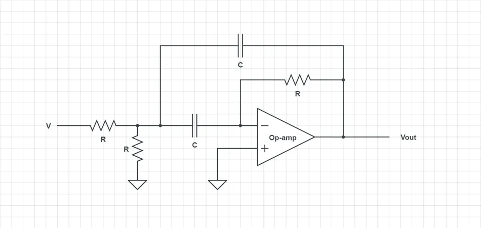
Multiple Feedback bandpass filter schematic
多重反馈带通滤波器原理图
State Variable Configuration (Kerwin-Huelsman-Newcomb Filter)
状态变量配置(克尔温-休尔斯曼-纽科姆滤波器)
-
Second-order filter topology using three op-amps, four resistors, and two capacitors.
二阶滤波器拓扑结构,使用三个运算放大器、四个电阻和两个电容。
-
Provides simultaneous low-pass, high-pass, and bandpass outputs.
可同时提供低通、高通和带通输出。
-
Transfer functions:
传递函数:
Low-pass filter (低通滤波器):
H l p ( s ) = 1 s 2 + s R 2 C 2 + 1 R 1 R 3 C 1 C 2 H_{lp}(s) = \frac{1}{s^{2} + \frac{s}{R_{2} C_{2}} + \frac{1}{R_{1} R_{3} C_{1} C_{2}}} Hlp(s)=s2+R2C2s+R1R3C1C211
Bandpass filter (带通滤波器):
H b p ( s ) = s R 1 C 1 s 2 + s R 2 C 2 + 1 R 1 R 3 C 1 C 2 H_{bp}(s) = \frac{\frac{s}{R_{1} C_{1}}}{s^{2} + \frac{s}{R_{2} C_{2}} + \frac{1}{R_{1} R_{3} C_{1} C_{2}}} Hbp(s)=s2+R2C2s+R1R3C1C21R1C1s
High-pass filter (高通滤波器):
H h p ( s ) = s 2 s 2 + s R 2 C 2 + 1 R 1 R 3 C 1 C 2 H_{hp}(s) = \frac{s^{2}}{s^{2} + \frac{s}{R_{2} C_{2}} + \frac{1}{R_{1} R_{3} C_{1} C_{2}}} Hhp(s)=s2+R2C2s+R1R3C1C21s2
-
Cutoff frequency:
截止频率:
ω 0 = 1 R 1 R 3 C 1 C 2 \omega_{0} = \frac{1}{\sqrt{R_{1} R_{3} C_{1} C_{2}}} ω0=R1R3C1C2 1 -
Quality factor:
品质因数:
Q = R 2 C 1 C 2 R 1 R 3 Q = \frac{R_2 \sqrt{C_1 C_2}}{\sqrt{R_1 R_3}} Q=R1R3 R2C1C2
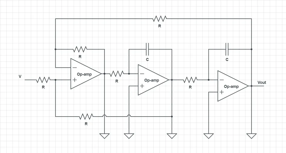
State Variable filter schematic
状态变量滤波器原理图
Advantages and Disadvantages of Each Configuration
各配置的优缺点
-
Sallen-Key : Simple and economical, but limited Q range and sensitivity to component variations.
萨伦-基:简洁经济,但 Q 值范围有限,且对组件变化敏感。 -
Multiple Feedback : Good high-Q performance, but higher component count and may require impedance matching.
多重反馈:高 Q 值性能优异,但组件数量较多,可能需要阻抗匹配。 -
State Variable : Multiple outputs and good control over Q, but highest component count and complexity.
状态变量:输出类型多,Q 值控制性好,但组件数量最多,复杂性最高。
Active Filter: Stability and Component Selection
有源滤波器:稳定性与组件选择
Stability is a critical consideration in the design of active filters, as unstable filters can lead to oscillations, distortion, and circuit damage. Active filter stability is closely related to component selection and circuit design, as the choice of op-amps, passive components, and circuit topology can significantly impact the filter's stability.
稳定性是有源滤波器设计中的关键考量因素,因为不稳定的滤波器可能会导致振荡、失真和电路损坏。有源滤波器的稳定性与组件选择和电路设计密切相关,运算放大器、无源组件和电路拓扑结构的选择会显著影响滤波器的稳定性。
Op-Amp Selection
运算放大器选择
-
Choose op-amps with high gain-bandwidth product (GBP) , low input noise, and good slew rate for active filter designs.
有源滤波器设计应选择高增益带宽积(GBP)、低输入噪声和良好压摆率的运算放大器。
-
Avoid op-amps with excessively high GBP , particularly in high-Q filters, to prevent stability issues.
避免使用增益带宽积过高的运算放大器,尤其是在高 Q 值滤波器中,以防出现稳定性问题。
-
Select an op-amp with sufficient GBP to meet the filter's frequency response requirements while maintaining an adequate phase margin.
选择增益带宽积足够的运算放大器,以满足滤波器的频率响应要求,同时保持足够的相位裕度。
Passive Component Selection
无源组件选择
-
Use high-quality, low-tolerance components with good temperature stability to minimize variations in the filter's response over time and temperature.
使用高质量、低公差且温度稳定性好的组件,以减少滤波器响应随时间和温度的变化。
-
Select capacitors with low equivalent series resistance (ESR) and low dielectric absorption to reduce the likelihood of instability caused by parasitic effects.
选择等效串联电阻(ESR)低且介电吸收小的电容,以降低寄生效应导致不稳定性的可能性。
Circuit Layout and Component Placement
电路布局与组件放置
-
Employ proper grounding techniques , such as using a single-point ground and minimizing ground loops, to reduce noise and prevent instability.
采用适当的接地技术,如单点接地和减少地环路,以降低噪声并防止不稳定性。 -
Place components close to the op-amp to minimize trace inductance and capacitance, which can introduce parasitic poles and zeros in the transfer function.
将组件靠近运算放大器放置,以最小化走线电感和电容,这些因素会在传递函数中引入寄生极点和零点。
Feedback Loop Design
反馈环路设计
-
Design the feedback loop to provide sufficient phase margin and gain margin, ensuring stable operation across the desired frequency range.
设计反馈环路以提供足够的相位裕度和增益裕度,确保在期望的频率范围内稳定工作。
-
Use techniques such as lead-lag compensation and pole-zero cancellation to improve the feedback loop's stability.
采用超前-滞后补偿和零极点抵消等技术,以提高反馈环路的稳定性。
Best Practices for Stable Active Filter Design
稳定有源滤波器设计的最佳实践
-
Select op-amps with appropriate GBP, noise, and slew rate characteristics for the desired filter specifications.
根据期望的滤波器规格,选择具有合适增益带宽积、噪声和压摆率特性的运算放大器。
-
Use high-quality, low-tolerance passive components with good temperature stability.
使用高质量、低公差且温度稳定性好的无源组件。
-
Minimize parasitic effects through careful circuit layout and component placement.
通过精心的电路布局和组件放置,最大限度地减少寄生效应。
-
Implement proper grounding techniques to reduce noise and prevent instability.
采用适当的接地技术,以降低噪声并防止不稳定性。
-
Design feedback loops with adequate phase margin and gain margin, using frequency compensation techniques when necessary.
设计具有足够相位裕度和增益裕度的反馈环路,必要时使用频率补偿技术。
-
Avoid excessively high Q factors , making the filter more susceptible to instability.
避免过高的 Q 值,否则会使滤波器更容易出现不稳定性。
-
Simulate the filter design using realistic component models and perform stability analysis to identify potential issues.
使用真实的组件模型对滤波器设计进行仿真,并进行稳定性分析,以识别潜在问题。
-
Prototype the filter and perform thorough testing to validate its stability under various operating conditions.
制作滤波器原型并进行全面测试,以验证其在各种工作条件下的稳定性。
Active filters leverage the control and amplification capabilities of op-amps to achieve more versatile and precise filtering functionalities compared to their purely passive counterparts. By incorporating these practices, users can enhance the overall design process and ensure the creation of highly stable and reliable active filters.
与纯无源滤波器相比,有源滤波器利用运算放大器的控制和放大能力,实现了更具通用性和精确性的滤波功能。通过采用这些实践方法,用户可以改进整体设计流程,确保设计出高度稳定可靠的有源滤波器。
Active Filter: Applications
有源滤波器的应用
Active filters offer enhanced performance, flexibility, and control compared to passive filters in various engineering fields. Some of the key application areas for active filters include signal conditioning, data acquisition, and control systems.
在各个工程领域,有源滤波器相比无源滤波器具有更优异的性能、灵活性和可控性。有源滤波器的主要应用领域包括信号调理、数据采集和控制系统。
In signal conditioning, active filters play a crucial role in improving signal quality and reducing noise. For example, an anti-aliasing filter is often used before analog-to-digital conversion to prevent high-frequency components from being aliased into the sampled signal.
在信号调理中,有源滤波器在提高信号质量和降低噪声方面起着关键作用。例如,在模数转换之前通常会使用抗混叠滤波器,以防止高频成分混叠到采样信号中。
In data acquisition systems, active filters are used for both pre-sampling and post-sampling signal conditioning. Pre-sampling filters, such as low-pass or band-pass filters, are used to limit the signal bandwidth and prevent aliasing before analog-to-digital conversion. Post-sampling filters, such as smoothing filters or decimation filters, are used to remove noise and improve the signal resolution after digital-to-analog conversion.
在数据采集系统中,有源滤波器用于采样前和采样后的信号调理。采样前滤波器(如低通或带通滤波器)用于限制信号带宽,防止模数转换前的混叠。采样后滤波器(如平滑滤波器或抽取滤波器)用于去除噪声,提高数模转换后的信号分辨率。
In control systems, active filters are used for various purposes, such as feedback loop compensation and noise reduction. For example, a lead-lag compensator can be implemented using an active filter to improve the system's stability and transient response. 4 The lead-lag compensator introduces a phase lead at higher frequencies to increase the phase margin and a phase lag at lower frequencies to reduce the steady-state error.
在控制系统中,有源滤波器有多种用途,如反馈环路补偿和噪声降低。例如,可以使用有源滤波器实现超前-滞后补偿器,以提高系统的稳定性和瞬态响应。4 超前-滞后补偿器在高频段引入相位超前,以增加相位裕度;在低频段引入相位滞后,以减少稳态误差。
Another example of active filters in control systems is notch filters for noise reduction. Notch filters are designed to attenuate a specific frequency or a narrow band of frequencies, such as power line interference or mechanical resonances. An active notch filter can be implemented using a twin-T network and an op-amp, providing high Q factors and sharp frequency selectivity.
控制系统中有源滤波器的另一个应用示例是用于降噪的陷波滤波器。陷波滤波器旨在衰减特定频率或窄频带,例如电源线干扰或机械共振。有源陷波滤波器可通过双 T 网络和运算放大器实现,具有高 Q 值和尖锐的频率选择性。
These are just a few examples, highlighting the versatility of active filters in shaping signals across various engineering applications. Other notable areas include audio signal processing, biomedical instrumentation, and communication systems.
这些只是几个示例,突显了有源滤波器在各个工程应用中信号整形的通用性。其他值得关注的领域包括音频信号处理、生物医学仪器和通信系统。
Components Used in Passive Filters
无源滤波器使用的组件
Passive filters are constructed using three main components: resistors, capacitors, and inductors. Each component plays a crucial role in shaping the frequency response of the filter.
无源滤波器由三个主要组件构成:电阻、电容和电感。每个组件在塑造滤波器的频率响应方面都起着关键作用。
Resistors are passive components that oppose the flow of electric current. The specific values of resistors, in conjunction with capacitors or inductors, determine the filter's cutoff frequency. They determine the shape of the frequency response curve. Resistors dissipate electrical energy as heat during their operation. This energy loss can contribute to a reduction in the overall signal strength, especially in high-power applications.
电阻是阻碍电流流动的无源组件。电阻的具体数值与电容或电感共同决定了滤波器的截止频率,并影响频率响应曲线的形状。电阻在工作过程中会将电能以热量的形式耗散,这种能量损失可能导致整体信号强度降低,在高功率应用中尤为明显。
Capacitors are passive components that store energy in an electric field. In passive filters, capacitors block low-frequency signals and pass high-frequency signals. They are used with other components to create high-pass and band-pass filters. Capacitors exhibit decreasing reactance with increasing frequency, allowing high-frequency signals to pass through while attenuating low-frequency signals.
电容是在电场中存储能量的无源组件。在无源滤波器中,电容可阻挡低频信号并让高频信号通过,常与其他组件配合构成高通滤波器和带通滤波器。电容的容抗随频率的增加而减小,因此允许高频信号通过,同时衰减低频信号。
Inductors are passive components that store energy in a magnetic field. In passive filters, inductors block high-frequency signals and pass low-frequency signals. They are used with other components to create low-pass and band-stop filters. Inductors exhibit increasing reactance with increasing frequency, allowing low-frequency signals to pass through while attenuating high-frequency signals.
电感是在磁场中存储能量的无源组件。在无源滤波器中,电感可阻挡高频信号并让低频信号通过,常与其他组件配合构成低通滤波器和带阻滤波器。电感的感抗随频率的增加而增大,因此允许低频信号通过,同时衰减高频信号。
Passive Filters: Circuit Configurations and Transfer Functions
无源滤波器:电路配置与传递函数
Passive filters can be designed in various circuit configurations to achieve desired frequency response characteristics. The four common circuit configurations are:
无源滤波器可通过多种电路配置实现,以获得期望的频率响应特性。四种常见的电路配置如下:

Passive Filters: Circuit Configurations and their Response
无源滤波器:电路配置及其响应
Low-Pass Filters
低通滤波器
Low-pass filters pass low-frequency signals while attenuating high-frequency signals. The basic low-pass filter consists of a resistor ® in series with a capacitor ©. The transfer function of a first-order low-pass filter is given by:
低通滤波器允许低频信号通过,同时衰减高频信号。基本的低通滤波器由串联的电阻(R)和电容(C)组成。一阶低通滤波器的传递函数为:
H ( s ) = 1 1 + s R C H(s) = \frac{1}{1 + sRC} H(s)=1+sRC1
where s s s is the complex frequency variable. The cutoff frequency ( f c f_c fc) is determined by:
其中 s s s 为复频率变量。截止频率( f c f_c fc)由下式确定:
f c = 1 2 π R C f_c = \frac{1}{2\pi RC} fc=2πRC1
A simple example of a passive low-pass filter would be hard walls that attenuate high-frequency components of an audio wave. This is precisely the reason why low-frequency notes of any audio are more legible in the adjacent room.
无源低通滤波器的一个简单例子是坚硬的墙壁,它会衰减声波中的高频成分。这也是为什么在相邻房间中,音频的低频音符更容易被听清的原因。

Low-Pass Filter
低通滤波器
High-Pass Filters
高通滤波器
High-pass filters pass high-frequency signals while attenuating low-frequency signals. The basic high-pass filter consists of a capacitor © in series with a resistor ®. The transfer function of a first-order high-pass filter is given by:
高通滤波器允许高频信号通过,同时衰减低频信号。基本的高通滤波器由串联的电容(C)和电阻(R)组成。一阶高通滤波器的传递函数为:
H ( s ) = s R C 1 + s R C H(s) = \frac{sRC}{1 + sRC} H(s)=1+sRCsRC
where s s s is the complex frequency variable. The cutoff frequency ( f c f_c fc) is determined by:
其中 s s s 为复频率变量。截止频率( f c f_c fc)由下式确定:
f c = 1 2 π R C f_c = \frac{1}{2\pi RC} fc=2πRC1
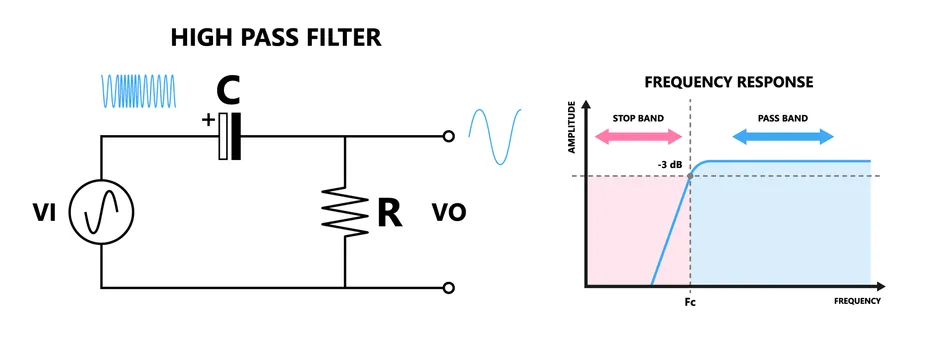
High-Pass Filter
高通滤波器
Band-Pass Filters
带通滤波器
Band-pass filters pass a specific range of frequencies while attenuating frequencies outside that range. 5 A simple band-pass filter can be created by cascading a low-pass filter and a high-pass filter. The transfer function of a second-order band-pass filter is given by:
带通滤波器允许特定频率范围的信号通过,同时衰减该范围外的频率。5 简单的带通滤波器可通过级联低通滤波器和高通滤波器实现。二阶带通滤波器的传递函数为:
H ( s ) = s Q ω 0 s 2 + s Q ω 0 + 1 ω 0 2 H(s) = \frac{\frac{s}{Q\omega_0}}{s^2 + \frac{s}{Q\omega_0} + \frac{1}{\omega_0^2}} H(s)=s2+Qω0s+ω021Qω0s
where Q Q Q is the quality factor, and ω 0 \omega_{0} ω0 is the center frequency. The quality factor determines the bandwidth of the filter, with higher Q Q Q values resulting in a narrower passband.
其中 Q Q Q 为品质因数, ω 0 \omega_{0} ω0 为中心频率。品质因数决定了滤波器的带宽, Q Q Q 值越高,通带越窄。
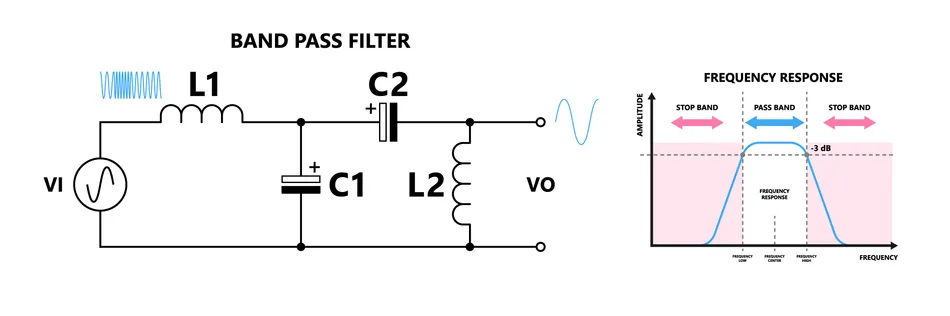
Band-Pass Filter
带通滤波器
Band-Stop Filters (Notch Filters)
带阻滤波器(陷波滤波器)
Band-stop filters, also known as notch filters, attenuate a specific range of frequencies while passing frequencies outside that range. A simple band-stop filter can be created by placing a series LC circuit in parallel with a resistor ®. The transfer function of a second-order band-stop filter is given by:
带阻滤波器(也称为陷波滤波器)衰减特定频率范围的信号,同时允许该范围外的频率通过。简单的带阻滤波器可通过将串联 LC 电路与电阻(R)并联实现。二阶带阻滤波器的传递函数为:
H ( s ) = s 2 + ω 0 2 s 2 + s ( ω 0 Q ) + ω 0 2 H(s) = \frac{s^{2} + \omega_{0}^{2}}{s^{2} + s\left(\frac{\omega_{0}}{Q}\right) + \omega_{0}^{2}} H(s)=s2+s(Qω0)+ω02s2+ω02
where Q Q Q is the quality factor, and ω 0 \omega_{0} ω0 is the notch frequency.
其中 Q Q Q 为品质因数, ω 0 \omega_{0} ω0 为陷波频率。
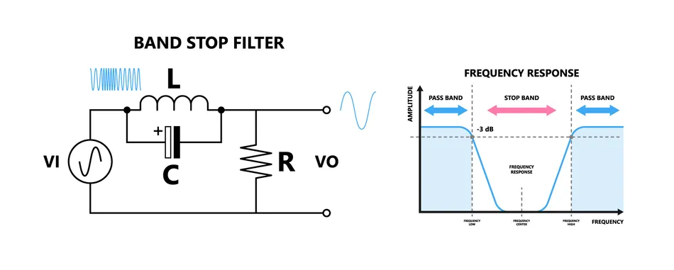
Band-Stop Filter or Notch Filter
带阻滤波器或陷波滤波器
Passive Filter: Stability and Component Selection
无源滤波器:稳定性与组件选择
Stability is a critical consideration in the design of passive filters. An unstable filter can lead to undesired oscillations, distortion, and even damage to the circuit. Filter stability is closely related to component selection and circuit design.
稳定性是无源滤波器设计中的关键考量因素。不稳定的滤波器可能会导致不期望的振荡、失真,甚至电路损坏。滤波器的稳定性与组件选择和电路设计密切相关。
Factors Affecting Filter Stability
影响滤波器稳定性的因素
-
Component tolerances : Resistors, capacitors, and inductors have inherent tolerances that can cause the actual filter response to deviate from the designed response, potentially causing instability, especially in high-order filters or those with narrow passbands.
组件公差:电阻、电容和电感具有固有公差,可能导致实际滤波器响应与设计响应偏离,尤其在高阶滤波器或窄通带滤波器中,可能引发不稳定性。
-
Parasitic effects : Parasitic inductance and capacitance introduced by components and circuit layout can create additional poles and zeros in the transfer function, leading to instability.
寄生效应:组件和电路布局引入的寄生电感和电容会在传递函数中产生额外的极点和零点,从而导致不稳定性。
Guidelines for Component Selection
组件选择指南
To ensure passive filter stability, engineers should follow these guidelines when selecting components:
为确保无源滤波器的稳定性,工程师在选择组件时应遵循以下指南:
-
Choose high-quality components with tight tolerances and low temperature coefficients to minimize deviations from the designed response.
选择公差小、温度系数低的高质量组件,以最大限度地减少与设计响应的偏差。
-
Consider the long-term stability and temperature coefficients of components to maintain filter performance over a wide range of operating conditions.
考虑组件的长期稳定性和温度系数,以确保滤波器在广泛的工作条件下保持性能。
-
Use temperature-compensated components or design with wider tolerance margins when necessary to account for component variations.
必要时使用温度补偿组件或设计更宽的公差裕度,以应对组件变化。
-
Select components with low parasitic effects and use circuit layout techniques to minimize their impact, such as using surface-mount components and minimizing trace lengths.
选择寄生效应低的组件,并采用电路布局技术(如使用表面贴装组件和缩短走线长度)最大限度地减少其影响。
Best Practices for Circuit Layout and Component Placement
电路布局与组件放置的最佳实践
Proper circuit layout and component placement play a crucial role in maintaining filter stability:
适当的电路布局和组件放置对维持滤波器稳定性至关重要:
-
Place components close together to minimize parasitic effects and keep signal paths as short as possible.
将组件靠近放置,以最小化寄生效应,并保持信号路径尽可能短。
-
Use ground planes and proper grounding techniques to provide a low-impedance return path for signals and reduce noise.
使用接地层和适当的接地技术,为信号提供低阻抗回流路径,并降低噪声。
-
Employ shielding or isolation techniques when necessary to prevent coupling between different sections of the filter.
必要时采用屏蔽或隔离技术,防止滤波器不同部分之间的耦合。
Simulation and Testing
仿真与测试
In addition to component selection and circuit layout, designers should:
除了组件选择和电路布局外,设计师还应:
-
Simulate the filter design using realistic component models and perform sensitivity analysis to identify potential stability issues.
使用真实的组件模型对滤波器设计进行仿真,并进行灵敏度分析,以识别潜在的稳定性问题。
-
Prototype the filter and conduct thorough testing under various operating conditions to validate its stability.
制作滤波器原型,并在各种工作条件下进行全面测试,以验证其稳定性。
Passive filters remain a fundamental building block in electronic circuits, offering a simple, cost-effective, and reliable solution for many signal processing applications. By understanding their basics, designers can make informed decisions when selecting the appropriate filter type and configuration for their specific requirements.
无源滤波器仍然是电子电路中的基本组成部分,为许多信号处理应用提供了简单、经济且可靠的解决方案。通过了解其基础知识,设计师可以在为特定需求选择合适的滤波器类型和配置时做出明智的决策。
Passive Filter: Applications
无源滤波器的应用
Passive filters, known for their simplicity and reliability, are used across various electrical engineering domains. Key application areas for passive filters include radio frequency (RF) communication, power supply systems, and audio electronics.
无源滤波器以其简洁性和可靠性而闻名,广泛应用于各个电气工程领域。其主要应用领域包括射频(RF)通信、电源系统和音频电子设备。
In RF communication systems , passive filters are essential for frequency selection and interference reduction. For example, band-pass filters allow a specific frequency band to reach the receiver or transmitter, effectively isolating desired signals from unwanted RF noise or signals. 6 This capability is critical in environments with multiple frequency signals, ensuring clear communication channels.
在射频通信系统中,无源滤波器对于频率选择和干扰降低至关重要。例如,带通滤波器允许特定频段的信号到达接收器或发射器,有效将所需信号与不需要的射频噪声或信号隔离。6 这种能力在存在多个频率信号的环境中至关重要,可确保通信信道清晰。
Power supply systems utilize passive filters to mitigate ripple and noise in DC power signals. A common application is the use of low-pass filters to smooth out the output of rectifiers, ensuring a steady DC supply by attenuating the AC components. This is crucial for the stability of electronic devices and systems that require consistent power quality.
电源系统利用无源滤波器来减轻直流电源信号中的纹波和噪声。一个常见的应用是使用低通滤波器来平滑整流器的输出,通过衰减交流成分确保稳定的直流供电。这对于需要稳定电源质量的电子设备和系统的稳定性至关重要。
Audio electronics benefit significantly from passive filters for tone control and crossover networks. High-pass and low-pass filters are employed in speakers to direct specific frequency ranges to the appropriate drivers - tweeters for high frequencies and woofers for low frequencies. This separation enhances the audio quality and performance of the sound system by matching the speaker components to their optimal frequency ranges.
音频电子设备从用于音调控制和分频网络的无源滤波器中受益匪浅。扬声器中采用高通和低通滤波器,将特定频率范围的信号导向相应的驱动单元------高音扬声器负责高频,低音扬声器负责低频。这种分离通过使扬声器组件匹配其最佳频率范围,提高了音响系统的音频质量和性能。
Furthermore, passive filters find applications in sensor signal conditioning, which help remove noise from sensor outputs before processing or display. By filtering out high-frequency noise, passive filters improve the accuracy and reliability of sensor measurements, essential for precise monitoring and control in industrial and scientific applications.
此外,无源滤波器还应用于传感器信号调理,在信号处理或显示之前去除传感器输出中的噪声。通过滤除高频噪声,无源滤波器提高了传感器测量的准确性和可靠性,这对于工业和科学应用中的精确监测和控制至关重要。
Other areas where passive filters are prominently used include automotive electronics, medical devices, and renewable energy systems, further highlighting their broad applicability and importance.
无源滤波器的其他主要应用领域包括汽车电子、医疗设备和可再生能源系统,这进一步突显了其广泛的适用性和重要性。
Factors Affecting Filter Performance
影响滤波器性能的因素
The performance of both passive and active filters can be influenced by various factors, such as component tolerances, temperature variations, and aging effects. These factors can cause deviations from the designed frequency response, leading to inaccuracies and instability in the filter's behavior.
无源滤波器和有源滤波器的性能都会受到多种因素的影响,例如组件公差、温度变化和老化效应。这些因素会导致实际频率响应与设计响应偏离,从而导致滤波器性能不准确和不稳定。
Component Tolerances
组件公差
-
Resistors, capacitors, and inductors have manufacturing tolerances that cause their actual values to differ from nominal values.
电阻、电容和电感存在制造公差,导致其实际值与标称值存在差异。
-
Variations can lead to shifts in cutoff frequency, changes in passband ripple, and variations in stopband attenuation.
这种差异可能导致截止频率偏移、通带纹波变化和阻带衰减波动。
-
Example: A 10% tolerance in a resistor value can cause a corresponding shift in the cutoff frequency of a first-order RC filter.
示例:电阻值存在 10% 的公差,可能导致一阶 RC 滤波器的截止频率发生相应偏移。
Temperature Variations
温度变化
-
Component values, such as resistors, capacitors, and inductors, can drift with temperature changes.
电阻、电容和电感等组件的数值会随温度变化而漂移。
-
Op-amp parameters, such as gain, bandwidth, and offset voltage, can also vary with temperature.
运算放大器的参数(如增益、带宽和失调电压)也会随温度变化。
-
Temperature-induced changes can lead to shifts in cutoff frequency, variations in passband ripple, and changes in stopband attenuation.
温度引起的变化可能导致截止频率偏移、通带纹波变化和阻带衰减波动。
Aging Effects
老化效应
-
Components like capacitors and inductors can experience value changes due to environmental factors (humidity, vibration, heat, or chemicals).
电容和电感等组件可能因环境因素(湿度、振动、热量或化学物质)而发生数值变化。
-
Long-term drift in filter behavior can occur, causing gradual deviations from the designed frequency response.
滤波器性能可能会出现长期漂移,导致与设计频率响应的逐渐偏离。
-
Example: Electrolytic capacitors can experience a decrease in capacitance and an increase in equivalent series resistance (ESR) over time, affecting cutoff frequency and damping characteristics.
示例:电解电容会随着时间的推移出现电容值下降和等效串联电阻(ESR)增加,从而影响截止频率和阻尼特性。
Impact on Accuracy and Stability
对准确性和稳定性的影响
-
Shifts in cutoff frequency can lead to insufficient attenuation of high-frequency components, resulting in aliasing and signal distortion (e.g., in anti-aliasing filters).
截止频率偏移可能导致高频成分衰减不足,从而导致混叠和信号失真(例如在抗混叠滤波器中)。
-
Changes in passband ripple can cause variations in signal-to-noise ratio and affect overall system performance (e.g., in communication systems).
通带纹波变化可能导致信噪比波动,并影响整体系统性能(例如在通信系统中)。
Mitigation Strategies
缓解策略
-
Design filters with sufficient tolerance margins to allow for component value variations without significantly affecting filter behavior.
设计具有足够公差裕度的滤波器,以允许组件数值变化而不会显著影响滤波器性能。
-
Use components with tight tolerances and low temperature coefficients (e.g., precision resistors and capacitors) to reduce the impact of component variations and temperature changes.
使用公差小、温度系数低的组件(如精密电阻和电容),以减少组件变化和温度变化的影响。
-
Employ proper circuit layout and shielding techniques to minimize the influence of external factors, such as electromagnetic interference (EMI) and thermal gradients.
采用适当的电路布局和屏蔽技术,最大限度地减少外部因素(如电磁干扰(EMI)和温度梯度)的影响。
-
Perform regular calibration and maintenance of filter circuits to identify and correct any long-term drift or degradation in performance.
对滤波器电路进行定期校准和维护,以识别并纠正任何长期漂移或性能下降。
Design Challenges and Trade-offs
设计挑战与权衡
Designing active and passive filters comes with certain challenges and trade-offs that must be carefully considered to achieve the desired performance while meeting cost and complexity constraints.
设计有源滤波器和无源滤波器面临着一定的挑战和权衡,必须仔细考虑这些因素,以在满足成本和复杂性限制的同时实现期望的性能。
Component Selection
组件选择
-
Balancing high-performance components with cost, availability, and package size.
在高性能组件与成本、可用性和封装尺寸之间取得平衡。
-
Component tolerances and parasitics can introduce variations in frequency response and affect filter stability.
组件公差和寄生效应可能导致频率响应变化,并影响滤波器稳定性。
-
Example: High-quality, tight-tolerance capacitors improve accuracy and repeatability of cutoff frequency but may come at a higher cost.
示例:高质量、公差小的电容可提高截止频率的准确性和可重复性,但成本可能更高。
Circuit Optimization
电路优化
-
Fine-tuning component values and circuit layout to achieve desired frequency response.
微调组件数值和电路布局,以实现期望的频率响应。
-
Time-consuming and iterative process, balancing optimal performance with design tool and fabrication process constraints.
这是一个耗时的迭代过程,需要在最佳性能与设计工具和制造工艺限制之间取得平衡。
-
Techniques like sensitivity analysis and Monte Carlo simulations help identify critical components and layout parameters.
灵敏度分析和蒙特卡洛仿真等技术有助于识别关键组件和布局参数。
Noise Reduction
噪声降低
-
Passive components (resistors, capacitors) can introduce thermal noise and shot noise.
无源组件(电阻、电容)会引入热噪声和散粒噪声。
-
Op-amps in active filters contribute to flicker noise and voltage noise.
有源滤波器中的运算放大器会产生闪烁噪声和电压噪声。
-
External noise sources (power supply ripple, EMI) can couple into the filter circuit and degrade signal-to-noise ratio.
外部噪声源(电源纹波、电磁干扰)可能耦合到滤波器电路中,降低信噪比。
-
Mitigation: Careful component selection, proper grounding and shielding, optimized circuit layout.
缓解措施:精心选择组件、适当接地和屏蔽、优化电路布局。
Performance vs. Cost vs. Complexity Trade-offs
性能、成本与复杂性的权衡
-
Increasing filter order improves selectivity and stopband attenuation but increases component count, cost, and design complexity.
增加滤波器阶数可提高选择性和阻带衰减,但会增加组件数量、成本和设计复杂性。
-
High-performance op-amps enhance filter performance but may require more expensive components and increase power consumption.
高性能运算放大器可提升滤波器性能,但可能需要更昂贵的组件,并增加功耗。
-
Passive filters: Simple and linear but limited control over frequency response and larger component values for low-frequency applications.
无源滤波器:简洁且线性,但对频率响应的控制有限,且在低频应用中需要更大的组件数值。
-
Active filters: Greater flexibility and higher Q factors but require power supply and may introduce noise and distortion. 7
有源滤波器:灵活性更高,Q 值更高,但需要电源供电,且可能引入噪声和失真。7
-
Switched-capacitor filters: Compact and integrated but limited frequency range and require anti-aliasing filters.
开关电容滤波器:紧凑且易于集成,但频率范围有限,且需要抗混叠滤波器。
Bringing a filter design from concept to reality requires navigating challenges and making informed choices. Analytical tools like SPICE simulations and frequency-domain analysis are useful, predicting filter behavior and allowing optimization of component values and circuit layout. For complex designs, optimization algorithms can automate the search for the best component combinations.
将滤波器设计从概念变为现实需要应对各种挑战并做出明智的选择。SPICE 仿真和频域分析等分析工具非常有用,它们可以预测滤波器性能,并允许优化组件数值和电路布局。对于复杂设计,优化算法可以自动搜索最佳组件组合。
Filter Approximation Methods
滤波器逼近方法
Filter approximation methods, also known as filter synthesis techniques, are mathematical approaches used to design filters with specific frequency response characteristics. These methods provide a systematic approach to design filters with specific characteristics like passband gain, stopband attenuation, and transition bandwidth. The most common filter approximation methods are:
滤波器逼近方法(也称为滤波器综合技术)是用于设计具有特定频率响应特性的滤波器的数学方法。这些方法为设计具有通带增益、阻带衰减和过渡带宽等特定特性的滤波器提供了系统的途径。最常见的滤波器逼近方法如下:
Butterworth Filter Approximation
巴特沃斯(Butterworth)滤波器逼近
This method prioritizes a maximally flat (smooth) response in the passband, resulting in a gradual roll-off from passband to stopband. It's a good choice for general-purpose filtering applications. The poles are evenly spaced around a circle in the s-plane, resulting in a stable and easily realizable filter.
该方法优先保证通带内的最大平坦(平滑)响应,导致从通带到阻带的滚降较为平缓。它是通用滤波应用的理想选择。巴特沃斯滤波器的极点在 s 平面上均匀分布在一个圆周围,因此滤波器稳定且易于实现。
Example of a third-order Butterworth low-pass filter transfer function:
三阶巴特沃斯低通滤波器传递函数示例:
H ( s ) = 1 s 3 + 2 s 2 + 2 s + 1 H(s) = \frac{1}{s^{3} + 2s^{2} + 2s + 1} H(s)=s3+2s2+2s+11
Chebyshev Filter Approximation
切比雪夫(Chebyshev)滤波器逼近
Chebyshev filter approximation is a technique used in signal processing to design filters with a specific desired frequency response. Compared to Butterworth filters (another common filter design method), Chebyshev filters achieve a sharper transition between the passband (frequencies allowed to pass) and stopband (frequencies attenuated). This is useful when you need to strictly limit unwanted frequencies.
切比雪夫滤波器逼近是信号处理中用于设计具有特定期望频率响应的滤波器的技术。与巴特沃斯滤波器(另一种常见的滤波器设计方法)相比,切比雪夫滤波器在通带(允许通过的频率)和阻带(被衰减的频率)之间实现了更陡峭的过渡。这在需要严格限制不需要的频率时非常有用。
The trade-off for the steeper roll-off is the presence of ripples in the passband (Type I Chebyshev) or stopband (Type II Chebyshev). Ripple amplitude and steepness of the roll-off are controlled by filter order and ripple factor.
更陡峭滚降的代价是通带(切比雪夫 I 型)或阻带(切比雪夫 II 型)中存在纹波。纹波幅度和滚降陡峭度由滤波器阶数和纹波系数控制。
-
Type I : Equiripple in the passband and monotonic response in the stopband
I 型:通带等纹波,阻带单调响应
-
Type II : Equiripple in the stopband and monotonic response in the passband
II 型:阻带等纹波,通带单调响应
Example of a third-order Chebyshev Type I low-pass filter transfer function with a 0.5 dB passband ripple:
通带纹波为 0.5 dB 的三阶切比雪夫 I 型低通滤波器传递函数示例:
H ( s ) = 0.2426 s 3 + 0.7426 s 2 + 1.2426 s + 0.2426 H(s) = \frac{0.2426}{s^{3} + 0.7426s^{2} + 1.2426s + 0.2426} H(s)=s3+0.7426s2+1.2426s+0.24260.2426
切比雪夫 I 型低通滤波器的传递函数通用形式为:
H ( s ) = K s 3 + a 2 s 2 + a 1 s + a 0 H(s) = \frac{K}{s^3 + a_2 s^2 + a_1 s + a_0} H(s)=s3+a2s2+a1s+a0K
Elliptic Filter Approximation (Cauer Filter)
椭圆(Cauer)滤波器逼近
An elliptic filter approximation, also known as a Cauer filter (after Wilhelm Cauer) or Zolotarev filter (after Yegor Zolotarev), is another technique in signal processing for designing filters with specific frequency responses. Elliptic filters boast the fastest transition between the passband (desired frequencies) and stopband (attenuated frequencies) of any filter type for a given order (complexity).
椭圆滤波器逼近(也称为考尔滤波器,以威廉·考尔命名;或佐洛塔列夫滤波器,以叶戈尔·佐洛塔列夫命名)是信号处理中另一种用于设计具有特定频率响应的滤波器的技术。对于给定的阶数(复杂性),椭圆滤波器在所有滤波器类型中具有通带(期望频率)和阻带(衰减频率)之间最快的过渡速度。
Unlike Chebyshev filters with ripple in just the passband (Type I) or stopband (Type II), elliptic filters exhibit ripple in both the passband and stopband. This ripple has a constant amplitude within each band.
与仅在通带(I 型)或阻带(II 型)存在纹波的切比雪夫滤波器不同,椭圆滤波器在通带和阻带中都存在纹波,且每个频段内的纹波幅度恒定。
Example of a third-order Elliptic low-pass filter transfer function with a 0.5 dB passband ripple and 40 dB stopband attenuation:
通带纹波为 0.5 dB、阻带衰减为 40 dB 的三阶椭圆低通滤波器传递函数示例:
H ( s ) = 0.2 s 3 + 0.6 s 2 + 0.5 s + 0.2 s 3 + 0.6 s 2 + 0.5 s + 0.2 H(s) = \frac{0.2s^{3} + 0.6s^{2} + 0.5s + 0.2}{s^{3} + 0.6s^{2} + 0.5s + 0.2} H(s)=s3+0.6s2+0.5s+0.20.2s3+0.6s2+0.5s+0.2
Computer-Aided Design Tools for Filter Simulation and Optimization
用于滤波器仿真和优化的计算机辅助设计(CAD)工具
Computer-aided design (CAD) tools play a crucial role in the simulation and optimization of filter circuits. These tools allow engineers to analyze filter performance, explore different design options, and optimize component values and circuit layouts without the need for physical prototyping.
计算机辅助设计(CAD)工具在滤波器电路的仿真和优化中起着至关重要的作用。这些工具使工程师能够分析滤波器性能、探索不同的设计方案,并优化组件数值和电路布局,而无需进行物理原型制作。
SPICE (Simulation Program with Integrated Circuit Emphasis)
SPICE(集成电路仿真程序)
SPICE (Simulation Program with Integrated Circuit Emphasis) is a widely used tool in the realm of electronic circuit design, specifically for analog circuits. It functions as a software program that simulates the behavior of electronic circuits before they are physically built. SPICE is a powerful circuit simulation tool for modeling and analyzing filter circuits.
SPICE 是电子电路设计领域(特别是模拟电路)中广泛使用的工具。它是一个软件程序,可在物理构建电子电路之前仿真其行为,是用于建模和分析滤波器电路的强大电路仿真工具。
Capabilities:
功能:
-
Transient analysis: Simulating the time-domain response of the filter to input signals
瞬态分析:仿真滤波器对输入信号的时域响应
-
AC analysis: Determining the frequency response of the filter, including magnitude and phase plots
交流分析:确定滤波器的频率响应,包括幅度和相位图
-
DC analysis: Calculating the operating point and bias conditions of the filter circuit
直流分析:计算滤波器电路的工作点和偏置条件
-
Monte Carlo analysis: Assessing the impact of component tolerances on filter performance
蒙特卡洛分析:评估组件公差对滤波器性能的影响
Example: SPICE netlist for a simple RC low-pass filter:
示例:简单 RC 低通滤波器的 SPICE 网表:
* RC Low-pass Filter
R1 IN OUT 1k
C1 OUT 0 1u
Vin IN 0 ac 1 dc 0
.ac dec 10 1 1Meg
.plot ac v(OUT)
.end
MATLAB
MATLAB
MATLAB is a powerful software platform for filter design and optimization. It excels in data analysis, algorithm development, and creating models to simulate real-world phenomena. This tool has an extensive library of built-in functions and toolboxes to start with the projects easily.
MATLAB 是一个强大的滤波器设计和优化软件平台。它在数据分析、算法开发和创建模拟现实世界现象的模型方面表现出色,拥有丰富的内置函数库和工具箱,便于快速开展项目。
Capabilities:
功能:
-
Filter synthesis: Designing filters based on specifications using functions like
butter(),cheby1(), andellip()滤波器综合:使用
butter()、cheby1()和ellip()等函数根据规格设计滤波器 -
Frequency response analysis: Plotting the magnitude and phase response of filters using functions like
freqz()andbode()频率响应分析:使用
freqz()和bode()等函数绘制滤波器的幅度和相位响应 -
Filter optimization: Optimizing filter coefficients and parameters using optimization toolboxes like
fminsearch()andfmincon()滤波器优化:使用
fminsearch()和fmincon()等优化工具箱优化滤波器系数和参数
Example: MATLAB code for designing a 4th-order Butterworth low-pass filter with a cutoff frequency of 1 kHz:
示例:设计截止频率为 1 kHz 的四阶巴特沃斯低通滤波器的 MATLAB 代码:
matlab
% Butterworth Low-pass Filter Design
fc = 1000;    % Cutoff frequency (Hz)
fs = 10000;   % Sampling frequency (Hz)
n = 4;        % Filter order
[b, a] = butter(n, fc/(fs/2), 'low');
freqz(b, a, 1024, fs);  % Plot frequency response
Other Popular CAD Tools
其他常用 CAD 工具
Keysight ADS Interface
是德科技 ADS 接口
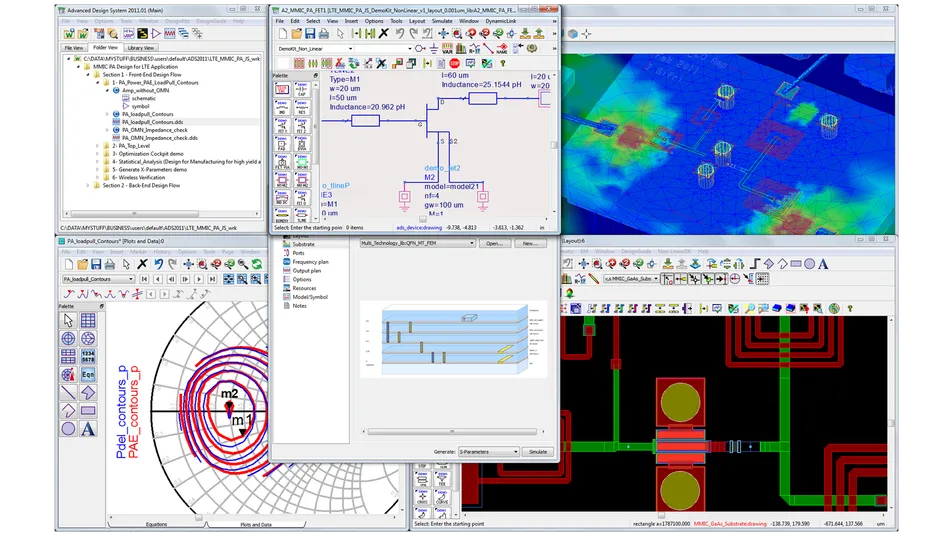
Keysight ADS
是德科技 ADS(先进设计系统)
Keysight ADS stands out as a powerful Electronic Design Automation (EDA) tool specifically designed for RF and microwave circuit design and simulation. It boasts integrated electromagnetic simulation capabilities through its Momentum tool, allowing engineers to analyze critical factors like signal integrity, power integrity, and electromagnetic interference (EMI) within their designs. Keysight ADS provides an environment where engineers can design and optimize filters while considering their performance within the larger context of the entire system.
是德科技 ADS 是一款强大的电子设计自动化(EDA)工具,专门用于射频和微波电路的设计和仿真。它通过其 Momentum 工具提供集成的电磁仿真功能,使工程师能够分析设计中的信号完整性、电源完整性和电磁干扰(EMI)等关键因素。是德科技 ADS 提供了一个环境,工程师可以在其中设计和优化滤波器,同时考虑其在整个系统中的性能。
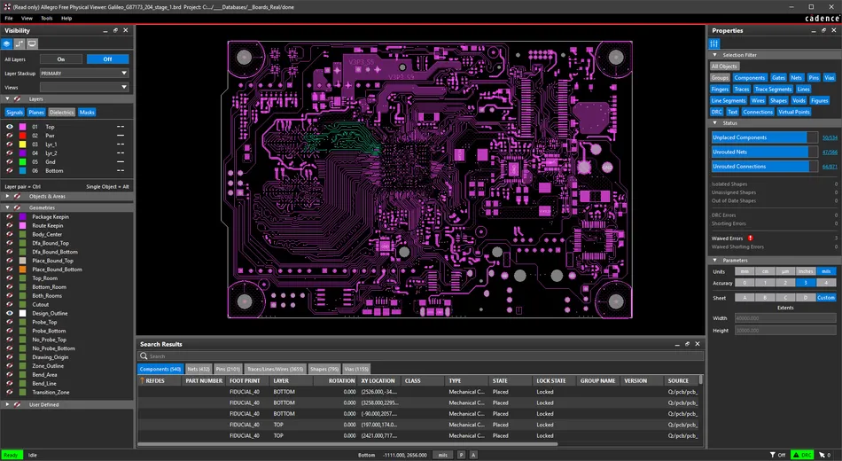
Cadence OrCAD
楷登电子 OrCAD
Cadence OrCAD is an industry-standard suite widely used for schematic capture, simulation, and layout tasks within the EDA field. For projects requiring advanced electromagnetic analysis, OrCAD integrates with Cadence EM Simulator, providing a robust solution. Cadence OrCAD maintains its focus on system-level design by offering seamless integration with Cadence Allegro, a popular and industry-standard PCB design tool. Finally, Cadence OrCAD includes filter design capabilities that allow engineers to consider the filter's role within the larger system during the design process.
楷登电子 OrCAD 是 EDA 领域中广泛用于原理图捕获、仿真和布局任务的行业标准套件。对于需要高级电磁分析的项目,OrCAD 与楷登电子 EM 模拟器集成,提供了强大的解决方案。通过与行业标准的 PCB 设计工具楷登电子 Allegro 无缝集成,OrCAD 专注于系统级设计。此外,楷登电子 OrCAD 还具备滤波器设计功能,使工程师能够在设计过程中考虑滤波器在整个系统中的作用。
Ansys Designer
安世亚太 Designer
Ansys Designer offers a comprehensive EDA experience by combining circuit design, simulation, and layout functionalities within a single platform. This all-in-one approach streamlines the design process. For in-depth electromagnetic analysis, Ansys Designer incorporates Ansys HFSS, a powerful simulation tool. The software seamlessly integrates with Ansys SIwave, a dedicated PCB design and signal integrity tool, ensuring a unified design environment throughout the project. Similar to Keysight ADS, Ansys Designer prioritizes filter design in context.
安世亚太 Designer 在单一平台中整合了电路设计、仿真和布局功能,提供了全面的 EDA 体验,这种一体化方法简化了设计流程。为进行深入的电磁分析,Ansys Designer 集成了强大的仿真工具 Ansys HFSS。该软件与专用的 PCB 设计和信号完整性工具 Ansys SIwave 无缝集成,确保在整个项目中提供统一的设计环境。与是德科技 ADS 类似,安世亚太 Designer 注重结合实际应用场景进行滤波器设计。
In summary, all three - Keysight ADS, Ansys Designer, and Cadence OrCAD - are powerful EDA tools that offer electromagnetic simulation capabilities, layout design features, and integration with PCB design software. They all allow engineers to design and optimize filters while considering their role within the larger electronic system. The choice of tool often depends on specific company preferences, existing software licenses, and the particular requirements of the design project.
总之,是德科技 ADS、安世亚太 Designer 和楷登电子 OrCAD 这三款工具都是强大的 EDA 工具,具备电磁仿真功能、布局设计特性以及与 PCB 设计软件的集成能力。它们都能让工程师在设计和优化滤波器的同时,考虑其在整个电子系统中的作用。工具的选择通常取决于公司的具体偏好、现有软件许可以及设计项目的特定要求。
Conclusion
结论
Active and passive filters, while fundamentally different, are both valuable tools for shaping signals in electronic engineering. Understanding their strengths (passive: simplicity, linearity; active: flexibility, gain) is key to effective filter selection. Modern design techniques like filter approximations and computer-aided tools (SPICE, MATLAB) further empower engineers to optimize filter performance. The rise of digital signal processing necessitates expertise in both analog and digital filter design to create robust solutions for the ever-growing demand.
有源滤波器和无源滤波器虽然存在本质差异,但都是电子工程中用于信号整形的宝贵工具。了解它们的优势(无源:简洁性、线性;有源:灵活性、增益)是有效选择滤波器的关键。滤波器逼近等现代设计技术和 SPICE、MATLAB 等计算机辅助工具进一步使工程师能够优化滤波器性能。随着数字信号处理的兴起,需要同时具备模拟和数字滤波器设计的专业知识,才能为不断增长的需求提供可靠的解决方案。
Frequently Asked Questions
常见问题
Q. What are the main differences between active and passive filters?
问:有源滤波器与无源滤波器的主要区别是什么?
A. Here are the differences:
答:主要区别如下:
-
Passive filters are constructed using only passive components (resistors, capacitors, and inductors), while active filters incorporate operational amplifiers alongside passive components.
无源滤波器仅使用无源组件(电阻、电容和电感)构建,而有源滤波器结合了无源组件和运算放大器。
-
Passive filters do not require a power source, whereas active filters need a power supply to operate.
无源滤波器不需要电源供电,而有源滤波器需要电源才能工作。
-
Active filters can provide gain and have greater control over filter characteristics, while passive filters are limited in their ability to shape the frequency response.
有源滤波器可以提供增益,并能更好地控制滤波器特性,而无源滤波器在频率响应整形方面的能力有限。
Q. How do I choose between a passive and an active filter for my application?
问:如何为我的应用选择无源滤波器或有源滤波器?
A. Follow these tips:
答:可遵循以下建议:
-
Consider factors such as the desired frequency response, signal levels, power handling requirements, and available space and budget.
考虑期望的频率响应、信号电平、功率处理要求以及可用空间和预算等因素。
-
Passive filters are often preferred for high-power applications, low-frequency designs, and situations where simplicity and reliability are crucial.
无源滤波器通常适用于高功率应用、低频设计以及对简洁性和可靠性要求较高的场景。
-
Active filters are suitable for applications requiring high Q factors, precise control over filter characteristics, and the ability to introduce gain.
有源滤波器适用于需要高 Q 值、精确控制滤波器特性以及需要引入增益的应用。
Q. What are the most common filter approximation methods, and how do they differ?
问:最常见的滤波器逼近方法有哪些?它们之间有何区别?
A. Butterworth, Chebyshev, and Elliptic are the most common filter approximation methods. These can be differentiated as:
答:最常见的滤波器逼近方法包括巴特沃斯、切比雪夫和椭圆法。它们的区别如下:
-
Butterworth filters have a maximally flat response in the passband but a slower roll-off in the stopband.
巴特沃斯滤波器通带响应最大平坦,但阻带滚降较慢。
-
Chebyshev filters have ripple in the passband (Type I) or stopband (Type II) but a steeper roll-off compared to Butterworth filters.
切比雪夫滤波器在通带(I 型)或阻带(II 型)存在纹波,但相比巴特沃斯滤波器滚降更陡峭。
-
Elliptic filters have ripple in both the passband and stopband but offer the steepest roll-off among the three approximations.
椭圆滤波器在通带和阻带均存在纹波,但在三种逼近方法中滚降最陡峭。
Q. What are the key factors to consider when selecting components for a filter design?
问:选择滤波器设计的组件时,关键考虑因素是什么?
A. Here are the key factors:
答:关键因素如下:
-
Consider the desired filter performance, such as cutoff frequency, passband ripple, and stopband attenuation.
考虑期望的滤波器性能,如截止频率、通带纹波和阻带衰减。
-
Choose components with appropriate values, tolerances, and temperature coefficients to ensure the filter meets the specified requirements.
选择具有适当数值、公差和温度系数的组件,以确保滤波器满足指定要求。
-
Take into account the power handling capabilities, voltage ratings, and parasitic effects of the components.
考虑组件的功率处理能力、电压额定值和寄生效应。
Q. How can computer-aided design tools assist in filter design and optimization?
问:计算机辅助设计工具如何帮助滤波器设计和优化?
A. CAD tools like SPICE and MATLAB allow engineers to simulate and analyze filter circuits, reducing the need for physical prototyping. These tools enable engineers to perform frequency response analysis, Monte Carlo simulations, and optimization of filter parameters. CAD tools can help identify potential issues, such as component tolerances and parasitic effects, and aid in selecting optimal component values.
答:SPICE 和 MATLAB 等 CAD 工具允许工程师仿真和分析滤波器电路,减少了对物理原型的需求。这些工具使工程师能够进行频率响应分析、蒙特卡洛仿真和滤波器参数优化。CAD 工具可以帮助识别组件公差和寄生效应等潜在问题,并协助选择最佳组件数值。
Q. What are the advantages of digital filters over analog filters?
问:数字滤波器相比模拟滤波器有哪些优势?
A. Digital filters offer programmability, adaptability, and the ability to achieve complex filter responses without the limitations of analog components. They are less susceptible to noise, drift, and component variations compared to analog filters. Digital filters can easily be integrated into digital signal processing systems and can be modified or updated through software changes.
答:数字滤波器具有可编程性、适应性强的特点,能够实现复杂的滤波器响应,而不受模拟组件的限制。与模拟滤波器相比,它们对噪声、漂移和组件变化的敏感性更低。数字滤波器可以轻松集成到数字信号处理系统中,并可通过软件修改进行更新。
Q. What are some common applications of active and passive filters in engineering?
问:有源滤波器和无源滤波器在工程中的常见应用有哪些?
A. Passive filters are used in power supply filtering, audio crossover networks, and RF and microwave signal conditioning. On the other hand, active filters are employed in applications such as audio equalizers, biomedical signal processing, and anti-aliasing filters for data acquisition systems. Both active and passive filters are used in telecommunications, control systems, and instrumentation to remove unwanted frequencies and improve signal quality.
答:无源滤波器用于电源滤波、音频分频网络以及射频和微波信号调理。有源滤波器则应用于音频均衡器、生物医学信号处理和数据采集系统的抗混叠滤波器等场景。有源滤波器和无源滤波器均用于电信、控制系统和仪器仪表中,以去除不需要的频率并提高信号质量。
References
参考文献
- 1 Sciencedirect. Chapter 8 - Prediction and Transforms Cited 2024 April 9 Available
科学指南(Sciencedirect). 第 8 章 - 预测与变换 引用日期:2024 年 4 月 9 日 - 2 Brahms. Chapter 12 - Active Filters Cited 2024 April 9 Available
Brahms. 第 12 章 - 有源滤波器 引用日期:2024 年 4 月 9 日 - 3 Open. 2.5 Normalised First-Order Low-Pass Filters Cited 2024 April 9 Available
Open. 2.5 归一化一阶低通滤波器 引用日期:2024 年 4 月 9 日 - 4 CTMS. Extras: Designing Lead and Lag Compensators Cited 2024 April 9 Available
CTMS. 补充内容:超前和滞后补偿器设计 引用日期:2024 年 4 月 9 日 - 5 electronics-tutorials. Passive Band Pass Filter Cited 2024 April 9 Available
电子教程(electronics-tutorials). 无源带通滤波器 引用日期:2024 年 4 月 9 日 - 6 allaboutcircuits. Understanding Linear-Phase Filters Cited 2024 April 9 Available
电路百科(allaboutcircuits). 线性相位滤波器详解 引用日期:2024 年 4 月 9 日 - 7 eng.libretexts. 11.3: The Use and Advantages of Active Filters Cited 2024 April 9 Available
工程自由文本(eng.libretexts). 11.3:有源滤波器的用途和优势 引用日期:2024 年 4 月 9 日
via:
- Difference between Active and Passive Filters?
https://www.wevolver.com/article/difference-between-active-and-passive-filters