硬件初始化及停止代码封装
硬件层串口初始化代码如下:
bsp_uart.h
c
#ifndef BSP_UART_H
#define BSP_UART_H

#include "stm32l4xx_hal.h"
#include <stdint.h>

// 串口波特率
#define BR_115200                       ((uint32_t)115200)

// 调试串口
#define DEBUG_UART      USART1
#define DEBUG_UART_CLK_ENABLE()         __HAL_RCC_USART1_CLK_ENABLE()
#define DEBUG_UART_CLK_DISABLE()        __HAL_RCC_USART1_CLK_DISABLE()

#define DEBUG_UART_GPIO_PORT            GPIOA
#define DEBUG_UART_GPIO_CLK_ENABLE()    __HAL_RCC_GPIOA_CLK_ENABLE()
#define DEBUG_UART_GPIO_CLK_DISABLE()   __HAL_RCC_GPIOA_CLK_DISABLE()
#define DEBUG_UART_TX_PIN               GPIO_PIN_9
#define DEBUG_UART_RX_PIN               GPIO_PIN_10
#define DEBUG_UART_AF                   GPIO_AF7_USART1

void BSP_UART_Init(uint32_t baudrate);
void BSP_UART_DeInit(void);

#endif
bsp_uart.c
c
#include "bsp_uart.h"

void BSP_UART_Init(uint32_t baudrate) {
    GPIO_InitTypeDef GPIO_InitData = {0};

    // 1. 开启时钟
    DEBUG_UART_GPIO_CLK_ENABLE();
    DEBUG_UART_CLK_ENABLE();

    // 2. 配置 TX 引脚: 复用推挽, 高速运行以减小信号畸变
    GPIO_InitData.Pin           = DEBUG_UART_TX_PIN;
    GPIO_InitData.Mode          = GPIO_MODE_AF_PP;   // 功能复用-推挽输出模式
    GPIO_InitData.Pull          = GPIO_PULLUP;       // 默认拉高, 保持空闲时状态稳定
    GPIO_InitData.Speed         = GPIO_SPEED_FREQ_VERY_HIGH;
    GPIO_InitData.Alternate     = DEBUG_UART_AF;
    HAL_GPIO_Init(DEBUG_UART_GPIO_PORT, &GPIO_InitData);

    // 3. 配置 RX 引脚: 复用模式
    GPIO_InitData.Pin           = DEBUG_UART_RX_PIN;
    HAL_GPIO_Init(DEBUG_UART_GPIO_PORT, &GPIO_InitData);

    // 4. 配置 UART 硬件参数 (直接操作寄存器,效率更高)
    // 禁用串口以进行配置
    DEBUG_UART->CR1 &= ~USART_CR1_UE;

    // 计算并设置波特率
    // 根据STM32L475xx block diagram 可知USART1挂在APB2总线上
    uint32_t pclk = HAL_RCC_GetPCLK2Freq();
    DEBUG_UART->BRR = (pclk + (baudrate / 2)) / baudrate; // 带四舍五入的波特率计算

    // 配置控制寄存器: 8N1模式, 使能发送与接收
    // CR1: M=00(8位), PCE=0(无校验), TE=1(发), RE=1(收)
    DEBUG_UART->CR1 = 0;
    DEBUG_UART->CR1 |= USART_CR1_TE;
    DEBUG_UART->CR1 |= USART_CR1_RE;

    // CR2: STOP=00(1个停止位)
    DEBUG_UART->CR2 = 0x0000;

    // CR3: 无硬件流控
    DEBUG_UART->CR3 = 0x0000;

    // 5. 使能串口
    DEBUG_UART->CR1 |= USART_CR1_UE;
}

void BSP_UART_DeInit(void)
{
    GPIO_InitTypeDef GPIO_InitData = {0};

    // 1. 【第一步:禁用串口所有功能,寄存器硬件级关闭,优先级最高】
    if(READ_BIT(DEBUG_UART->CR1, USART_CR1_UE) != RESET) // 判断串口是否使能
    {
        DEBUG_UART->CR1 &= ~(USART_CR1_UE | USART_CR1_TE | USART_CR1_RE); // 关闭串口总开关+发送+接收
        DEBUG_UART->CR2 = 0x0000;  // 复位串口控制寄存器2
        DEBUG_UART->CR3 = 0x0000;  // 复位串口控制寄存器3
        DEBUG_UART->BRR = 0x0000;  // 复位波特率寄存器
    }

    // 2. 【第二步:GPIO引脚彻底失能,配置为 浮空输入 高阻态】
    // 浮空输入:GPIO口无上下拉、无驱动,彻底切断硬件电平干扰,功耗最低,是GPIO关闭的标准配置
    GPIO_InitData.Mode        = GPIO_MODE_INPUT;       // 输入模式
    GPIO_InitData.Pull        = GPIO_NOPULL;           // 无上下拉 → 高阻态
    GPIO_InitData.Speed       = GPIO_SPEED_FREQ_LOW;   // 低速(关闭高速驱动,降低功耗)

    // 反初始化TX引脚
    GPIO_InitData.Pin         = DEBUG_UART_TX_PIN;
    HAL_GPIO_Init(DEBUG_UART_GPIO_PORT, &GPIO_InitData);
    // 反初始化RX引脚
    GPIO_InitData.Pin         = DEBUG_UART_RX_PIN;
    HAL_GPIO_Init(DEBUG_UART_GPIO_PORT, &GPIO_InitData);

    // 3. 【第三步:关闭GPIO时钟,彻底切断GPIO模块供电】
    DEBUG_UART_GPIO_CLK_DISABLE();

    // 4. 【第四步:关闭串口内核时钟,彻底关闭串口外设,最后执行】
    DEBUG_UART_CLK_DISABLE();
}
关于上述代码涉及到的知识点
1. 开启时钟时, 要开启RCC_USART1_CLK和RCC_GPIOA_CLK两个模块的时钟
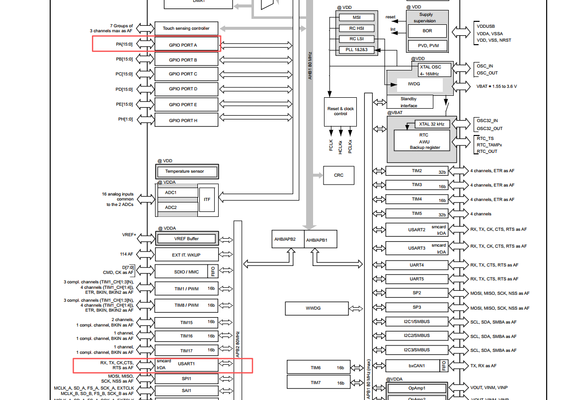
通过系统模块图可知, USART1模块是挂在APB2总线上的一个独立模块, GPIOA是挂在AHB总线上的一个模块, 所以要两个独立使能时钟.
2. 关于对GPIO设置的每一项的含义
GPIO_InitData.Pin           = DEBUG_UART_TX_PIN;
GPIO_InitData.Mode          = GPIO_MODE_AF_PP;   // 功能复用-推挽输出模式
GPIO_InitData.Pull          = GPIO_PULLUP;       // 默认拉高, 保持空闲时状态稳定
GPIO_InitData.Speed         = GPIO_SPEED_FREQ_VERY_HIGH;
GPIO_InitData.Alternate     = DEBUG_UART_AF;
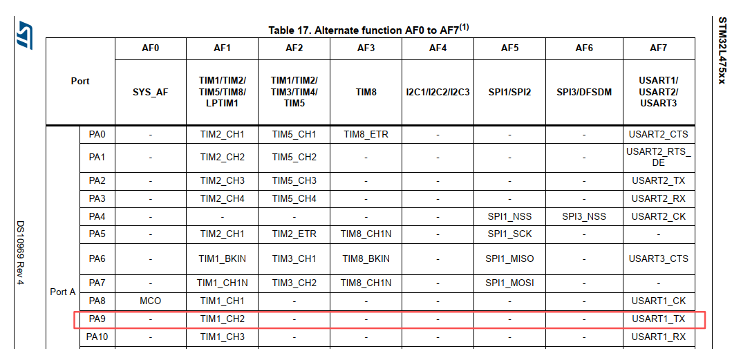
根据原理图可知TX_PIN为PA9
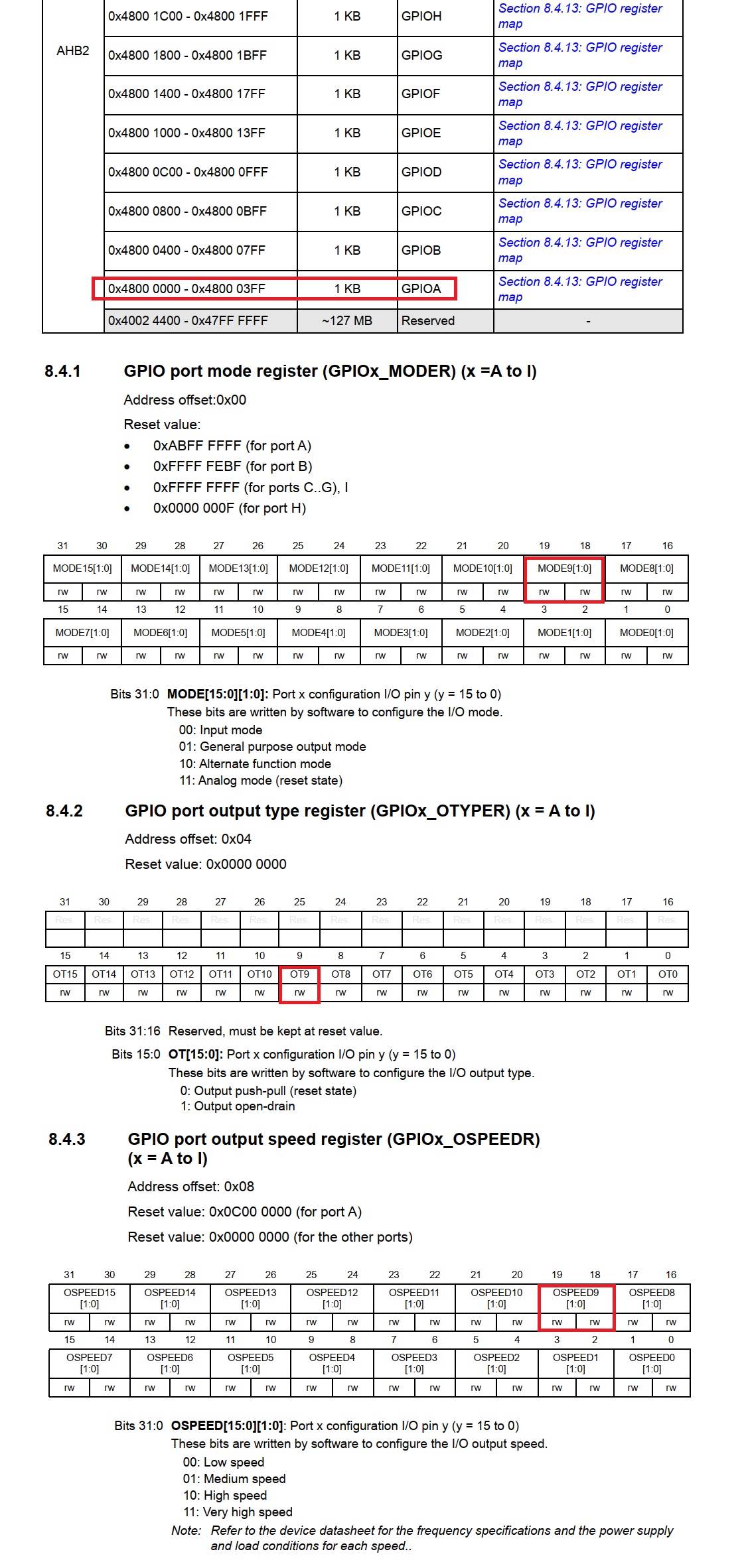
GPIO_InitData.Mode设置的是GPIO脚的IO工作模式, 总共有4种, 还有输出类型, 有两种
These bits are written by software to configure the I/O mode.
00: Input mode 输入模式
01: General purpose output mode 通用输出模式
10: Alternate function mode 复用功能模式 (必须选择这个模式, 才能在功能复用时选择串口功能)
11: Analog mode (reset state) 模拟模式

These bits are written by software to configure the I/O output type.
0: Output push-pull (reset state) 推挽输出
1: Output open-drain 开漏输出
相关文档原文如图
复用功能对应的功能编号如下, 配置为AF7即代表串口USART1_TX功能
然后执行HAL_GPIO_Init(DEBUG_UART_GPIO_PORT, &GPIO_InitData);完成上述所有寄存器的配置
RX的配置更换pin脚即可, 其他配置和TX一样
3. 串口参数配置
DEBUG_UART->BRR = (pclk + (baudrate / 2)) / baudrate; // 带四舍五入的波特率计算
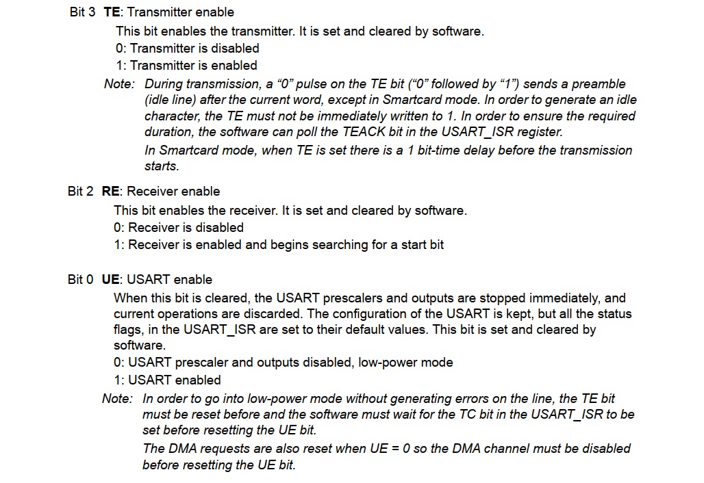
// 配置控制寄存器: 8N1模式, 使能发送与接收
// CR1: M=00(8位), PCE=0(无校验), TE=1(发), RE=1(收)
DEBUG_UART->CR1 = 0;
DEBUG_UART->CR1 |= USART_CR1_TE;
DEBUG_UART->CR1 |= USART_CR1_RE;
// CR2: STOP=00(1个停止位)
DEBUG_UART->CR2 = 0x0000;
// CR3: 无硬件流控
DEBUG_UART->CR3 = 0x0000;
// 5. 使能串口
DEBUG_UART->CR1 |= USART_CR1_UE;相关寄存器文档如下
串口打印功能封装
硬件初始化完成后, 就可以通过串口传送数据了.
如果我们使用Keil编译器中集成的标准库stdio.h, 会导致编译出来的hex文件非常大, 总共flash就512kb大小, 标准库打印功能就占到了40kb+, 这不是我们想要的. 所以, 采用第三方实现的打印print函数
主要有两个
mpaland/printf 和 charlesnicholson/nanoprintf
本文将基于mpaland/printf封装一个适用与生产环境的打印库
根据文档, 在printf.h中增加如下禁用宏定义, 将浮点数, 自然常数, 长整数和制表符打印全禁掉,
这样编译出来的printf.o会更小, 约2kb
c
// Define this to disable floating point (%f) support
#define PRINTF_DISABLE_SUPPORT_FLOAT
// Define this to disable exponential floating point (%e) support
#define PRINTF_DISABLE_SUPPORT_EXPONENTIAL
// Define this to disable long long (%ll) support
#define PRINTF_DISABLE_SUPPORT_LONG_LONG
// Define this to disable ptrdiff_t (%t) support
#define PRINTF_DISABLE_SUPPORT_PTRDIFF_T
然后我们开始封装trace_cfg.h, trace.h, trace.c, 基于printf实现的打印库
trace_cfg.h
c
#ifndef TRACE_CFG_H
#define TRACE_CFG_H

/* 全局总开关 */
#define TRACE_ENABLE 1

/* 日志等级 */
#define TRACE_LEVEL_ERROR   1
#define TRACE_LEVEL_WARN    2
#define TRACE_LEVEL_INFO    3
#define TRACE_LEVEL_DEBUG   4

/* 当前编译等级 */

#define TRACE_LEVEL     TRACE_LEVEL_DEBUG

#endif
trace.h
c
#ifndef TRACE_H
#define TRACE_H

#include "trace_cfg.h"
#include "stm32l4xx_hal.h"

#if TRACE_ENABLE

void trace_printf(const char *fmt, ...);
uint32_t trace_get_timestamp_ms(void);

#define TRACE_ERROR(fmt, ...)                               \
    do {                                                    \
        if (TRACE_LEVEL >= TRACE_LEVEL_ERROR)               \
            trace_printf("[E] " fmt "\r\n", ##__VA_ARGS__); \
    } while (0)

#define TRACE_WARN(fmt, ...)                                \
    do {                                                    \
        if (TRACE_LEVEL >= TRACE_LEVEL_WARN)                \
            trace_printf("[W] " fmt "\r\n", ##__VA_ARGS__); \
    } while (0)

#define TRACE_INFO(fmt, ...)                                \
    do {                                                    \
        if (TRACE_LEVEL >= TRACE_LEVEL_INFO)                \
            trace_printf("[I] " fmt "\r\n", ##__VA_ARGS__); \
    } while (0)

#define TRACE_DEBUG(fmt, ...)                               \
    do {                                                    \
        if (TRACE_LEVEL >= TRACE_LEVEL_DEBUG) {             \
            trace_printf("[D][%lums][%s:%d] " fmt "\r\n",   \
                          trace_get_timestamp_ms(),         \
                          __FILE__,                         \
                          __LINE__,                         \
                          ##__VA_ARGS__);                   \
        }                                                   \
    } while (0)

#else /* TRACE_ENABLE == 0 */

#define TRACE_ERROR(...)    ((void)0)
#define TRACE_WARN(...)     ((void)0)
#define TRACE_INFO(...)     ((void)0)
#define TRACE_DEBUG(...)    ((void)0)

#endif // TRACE_ENABLE

#endif // TRACE_H
trace.c
c
#include "trace.h"
#include "printf.h"
#include <stdarg.h>


#if TRACE_ENABLE

void trace_printf(const char *fmt, ...)
{
    va_list va;
    va_start(va, fmt);
    vprintf(fmt, va);
    va_end(va);
}

uint32_t trace_get_timestamp_ms(void)
{
  return uwTick;
}

#endif
然后, 当调用printf时, 根据文档, 我们需要基于当前硬件环境实现_putchar函数接口, printf库将基于此功能实现所有的打印.
于是, 我们的接口封装如下
c
void BSP_UART_SendByte(uint8_t byte)
{
    // 如果字符是 \n,自动补齐 \r (标准终端需要)
    if (byte == '\n') {
        while (!(DEBUG_UART->ISR & USART_ISR_TXE));
        DEBUG_UART->TDR = '\r';
    }

    while (!(DEBUG_UART->ISR & USART_ISR_TXE));
    DEBUG_UART->TDR = byte;
}

void _putchar(char character)
{
    BSP_UART_SendByte((uint8_t)character);
}
至此, 就封装好了地占用高效的printf串口打印功能, 可以用来调试.
在实际项目中, 调试阶段要用调试功能, 但是最终发布应用时, 要将串口模块从硬件上完全关闭掉, 代码应用层则禁用所有的打印, 以此实现节省功耗.
最终调用
c
#include "main.h"
#include "bsp_clock.h"
#include "bsp_uart.h"
#include "trace.h"

int main(void) {
    HAL_Init();           // 1. 初始化HAL库(配置SysTick等)

    SystemClock_Config();
    BSP_UART_Init(BR_115200);

    int counter = 0;
    while (1) {
        counter++;

        TRACE_DEBUG("this is debug working %d", counter);
        TRACE_INFO("this is info working %d", counter);
        TRACE_ERROR("this is error working %d", counter);
        TRACE_WARN("this is warning working %d", counter);

        HAL_Delay(1000);
    }
}
串口输出:
[D][7093ms][..\Src\main.c:16] this is debug working 8
[I] this is info working 8
[E] this is error working 8
[W] this is warning working 8
[D][8106ms][..\Src\main.c:16] this is debug working 9
[I] this is info working 9
[E] this is error working 9
[W] this is warning working 9
[D][9119ms][..\Src\main.c:16] this is debug working 10
[I] this is info working 10
[E] this is error working 10
[W] this is warning working 10