一,简介
本文在Catlike Coding 实现的【Custom SRP 2.5.0】基础上参考知乎文章Unity实现Decal贴花和运用 实现相关功能。
二,环境
Unity :2022.3.18f1
CRP Library :14.0.10
URP基本结构 :Custom SRP 2.5.0
三,实现
贴花里最重要的概念是投影,好比拿喷漆在物体表面上喷射一样。
在工程上的实现具体要考虑的是要在哪里画。为此需要实现两个点,一是限制绘制范围,二是绘制的点在贴图上的相对位置。
本文通过Stencil Box的方式实现。
在场景中创建一个Cube,创建新的shader与材质并挂上后,在Shader添加如下代码。
Shader "Custom/DecalShader"
{
    Properties
    {
        _MainTex ("Texture", 2D) = "white" {}
    }
    SubShader
    {
        HLSLINCLUDE
		#include "Custom RP/ShaderLibrary/Common.hlsl"
		#include "Custom RP/ShaderLibrary/LitInput.hlsl"
		ENDHLSL

        Pass
        {
           Stencil
           {
               Ref 1
               Comp Always
               Pass Replace
           }

           ZTest GEqual
           ZWrite Off
           Cull Front
           ColorMask 0


            HLSLPROGRAM
            #pragma vertex vert
            #pragma fragment frag


            struct appdata
            {
                float4 vertex : POSITION;
            };

            struct v2f
            {
                float2 uv : TEXCOORD0;
                float4 vertex : SV_POSITION;
            };


            sampler2D _MainTex;
            float4 _MainTex_ST;

            v2f vert (appdata v)
            {
                v2f o;
                o.vertex = TransformObjectToHClip(v.vertex);
                return o;
            }
            float4 frag (v2f i) : SV_Target
            {
                return 0;
            }
            ENDHLSL
        }


    }
}
注意 :Include 中的hlsl代码是Custom SRP 2.5.0中的实现,他封装并自己实现了一些SRP中HLSL相关功能。TransformObjectToHClip 这个函数是Unity中封装的函数。
这个Pass的主要目的是限制绘制范围,通过深度比较将需要绘制的区域写入到模板里面。
在去掉 ColorMask 0 后你会看到这样的场景。
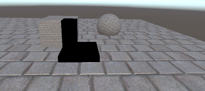
黑色区域就是需要绘制的区域。
然后就是要知道这些黑色区域的地方对应的是贴图那个位置了。这也是投影这个概念要应用的地方。
获取这个位置需要分成三个步骤。
1,知道当前渲染点的世界空间坐标。
2,知道当前渲染点的本地空间坐标。
3,转换本地空间坐标到贴图uv。
具体实现代码如下:
Pass
{
    Tags { "LightMode"="CustomLit" }


   Stencil
   {
       Ref 1
       Comp Equal
       Pass Keep
   }

   Blend SrcAlpha OneMinusSrcAlpha
   ZWrite Off
   Cull Back

    HLSLPROGRAM
    #pragma vertex vert
    #pragma fragment frag

    struct appdata
    {
        float4 vertex : POSITION;
    };

    struct v2f
    {
        float4 vertex : SV_POSITION;

    };


    sampler2D _MainTex;
    float4 _MainTex_ST;
    float4x4 _WorldToDecal;


    v2f vert (appdata v)
    {
        v2f o;
        o.vertex = TransformObjectToHClip(v.vertex);
        return o;
    }


    float4 frag (v2f i) : SV_Target
    {
        float2 posUV = i.vertex.xy / _ScreenParams.xy;
        float3 wpos = GetWorldPosByScreenUV(posUV);

        // 转换到贴花本地空间
        float3 decalPos = mul(_WorldToDecal, float4(wpos, 1)).xyz;

        float2 uv = decalPos.xz + 0.5;

        float4 col = tex2D(_MainTex, uv);
        return col;
    }
    ENDHLSL
}
获取世界空间坐标的时候需要注意,不能简单的通过当前像素的裁切空间坐标转换到世界空间,虽然这确实能拿到当前像素的世界空间坐标,但与实际需要的像素点的世界空间坐标不对应。这是因为第二个Pass在渲染的时候ZTest 默认是 LEqual,通过模板测试,且深度不在绘制范围的片元都经过了渲染,从逻辑上来说这里ZTest 应该设置为Equal,这样片元上的的世界空间坐标就是我们需要的坐标了,但是设置为Equal的时候Pass渲染不出结果,原因不明。
所以获取世界空间坐标的方式改为从深度图重建世界空间坐标。
GetWorldPosByScreenUV 相关实现如下:
// 根据线性深度值和屏幕UV,还原世界空间下,相机到顶点的位置偏移向量
half3 ReconstructViewPos(float2 uv, float linearEyeDepth) {
	// Screen is y-inverted
	uv.y = 1.0 - uv.y;

	float zScale = linearEyeDepth * _ProjectionParams2.x; // divide by near plane
	float3 viewPos = _CameraViewTopLeftCorner.xyz + _CameraViewXExtent.xyz * uv.x + _CameraViewYExtent.xyz * uv.y;
	viewPos *= zScale;

	return viewPos;
}

float3 GetViewPosByScreenUV(float2 uv) {
	//深度图重构观察空间坐标
	float depth = SAMPLE_DEPTH_TEXTURE_LOD(_CameraDepthTexture, sampler_point_clamp, uv, 0);
	depth = IsOrthographicCamera() ? OrthographicDepthBufferToLinear(depth) : LinearEyeDepth(depth, _ZBufferParams);

	return ReconstructViewPos(uv, depth);
}

float3 GetWorldPosByScreenUV(float2 uv) {
	//深度图重构世界坐标
	float3 vpos = GetViewPosByScreenUV(uv);
	float3 wpos = _WorldSpaceCameraPos + vpos;
	return wpos;
}
部分参数从C# 传入:
	void SetCameraParams(CommandBuffer buffer)
	{
		Matrix4x4 view = camera.worldToCameraMatrix;
		Matrix4x4 proj = camera.projectionMatrix;

		// 将camera view space 的平移置为0,用来计算world space下相对于相机的vector
		Matrix4x4 cview = view;
		cview.SetColumn(3, new Vector4(0.0f, 0.0f, 0.0f, 1.0f));
		Matrix4x4 cviewProj = proj * cview;

		// 计算viewProj逆矩阵,即从裁剪空间变换到世界空间
		Matrix4x4 cviewProjInv = cviewProj.inverse;

		// 计算世界空间下,近平面四个角的坐标
		var near = camera.nearClipPlane;

		Vector4 topLeftCorner = cviewProjInv.MultiplyPoint(new Vector4(-1.0f, 1.0f, -1.0f, 1.0f));
		Vector4 topRightCorner = cviewProjInv.MultiplyPoint(new Vector4(1.0f, 1.0f, -1.0f, 1.0f));
		Vector4 bottomLeftCorner = cviewProjInv.MultiplyPoint(new Vector4(-1.0f, -1.0f, -1.0f, 1.0f));

		// 计算相机近平面上方向向量
		Vector4 cameraXExtent = topRightCorner - topLeftCorner;
		Vector4 cameraYExtent = bottomLeftCorner - topLeftCorner;

		//设置参数
		buffer.SetGlobalVector(CameraViewTopLeftCorner, topLeftCorner);
		buffer.SetGlobalVector(CameraViewXExtent, cameraXExtent);
		buffer.SetGlobalVector(CameraViewYExtent, cameraYExtent);
		buffer.SetGlobalVector(ProjectionParams2, new Vector4(1.0f / near, camera.transform.position.x, camera.transform.position.y, camera.transform.position.z));

	}
得到渲染点在世界空间坐标后,将该世界空间坐标通过物体本身的转换矩阵转换到本地空间坐标。
_WorldToDecal获取如下:
using System.Collections;
using System.Collections.Generic;
using UnityEngine;
public class CustomDecal : MonoBehaviour
{
static MaterialPropertyBlock block;
// Start is called before the first frame update
void Start()
{
SetPropertyBlock();
}
void OnValidate()
{
SetPropertyBlock();
}
// Update is called once per frame
void Update()
{
SetPropertyBlock();
}
private void SetPropertyBlock()
{
if (block == null)
{
block = new MaterialPropertyBlock();
}
// 获取从世界空间到该物体局部空间的变换矩阵
Matrix4x4 worldToDecal = transform.worldToLocalMatrix;
// 将矩阵设置到材质中
block.SetMatrix("_WorldToDecal", worldToDecal);
GetComponent<Renderer>().SetPropertyBlock(block);
}
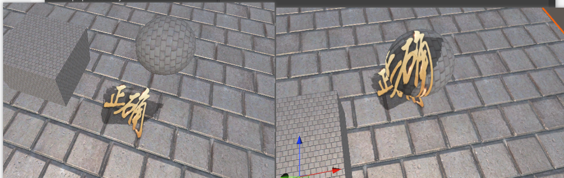
}最后只要获得本地空间坐标的话根据投射角度选择对应的xz值,至此投影效果便实现了。
效果如下:
参考资料: