一、参数
|------|-----------------------------------------------|
| 参数 | 数值 |
| 检测范围 | -55℃~125℃ |
| 精度 | ±0.5v |
| 工作电压 | 3v~5.5v |
| 分辨率 | 9位:0.5℃ 10位:0.25℃ 11位:0.0125℃ 12位(默认): 0.0625 |
二、操作ROM指令
读 ROM(0x33)
搜索ROM(0xF0)
匹配ROM(0x55)
跳过ROM(0xCC)
报警搜索(0xEC)
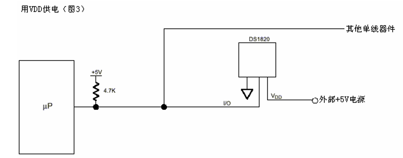
接上拉电阻的目的;
51单片机拉高,DS18B20拉高,引脚保持高电平
三、温度采集流程
复位:发送复位脉冲,拉低总线,然后释放,等待传感器响应脉冲
发送0xCC,跳过ROM:单总线指令,跳过ROM寻址,直接操作芯片
发送0x44,开启温度转换
延时1s:保证温度转换完成
复位:重新初始化总线,为读取数据做准备
发送0xCC,跳过ROM:再次跳过ROM,准备读取数据
发送0xBE,读取温度
读取两个字节温度:先读低字节,在读高字节,组合成最终温度值
四、DS18B20时序
复位: 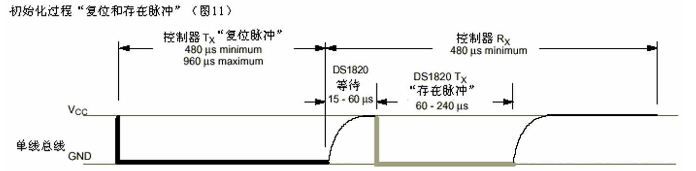
主机先将总线拉低至少480us,再释放总线(至少15us),代表主机发送了一个复位脉冲
主机如果在60~240us检测到总线出现低电平,代表DS18B20恢复了一个"存在脉冲"
DS18B20最终释放总线,总线为高电平
写时序:
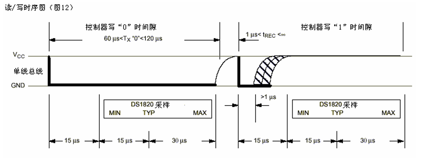
写0时序:
主机总线拉低大于60us
DS18B20在60us内进行采样,如果采到低电平,代表主机发送了一个'0'
主机释放总线,将引脚拉高
写1时序:
主机将总线拉低大于1us
主机释放总线,将引脚拉高
DS18B20在45us内进行采样,如果采到高电平,代表主机发了一个1
读时序:
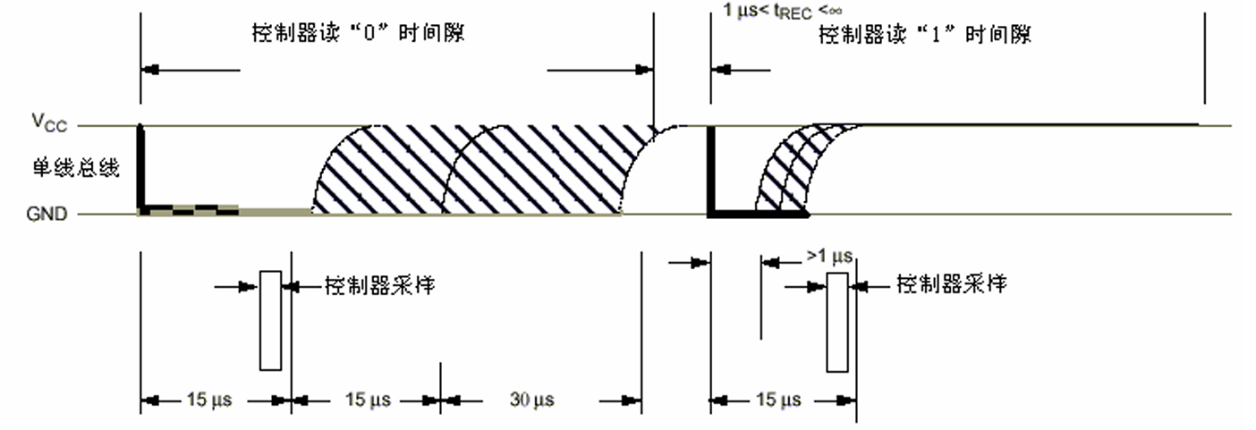
主机将总线拉低大于1us,释放总线,引脚变为高电平
主机在15u内采样
若采到一个高电平,代表读到1
若采到一个低电平,代表读到0
最终DS18B20释放总线
示例代码:
cpp
#include <reg51.h>
#include "bs18b20.h"
#include "delay.h"
#include "uart.h"
#include <intrins.h>
#include <stdio.h>

#define PIN_HIGH		(P3 |= (1 << 7))  //将P37引脚拉高
#define PIN_LOW			(P3 &= ~(1 << 7)) //将P37引脚拉低
#define PIN_CHECK		((P3 & (1 << 7))!= 0) //判断是否为高电平

//复位
int Bs18b20_Reset(void)
{
	int time = 0;
	//发送一个复位脉冲
	PIN_LOW;
	Delay10us(70);
	PIN_HIGH;
	Delay10us(5);

	//等待低电平到来
	while(PIN_CHECK && time < 30)
	{
		Delay10us(1);
		time++;
	}
	if(time >= 30)
	{
		UartSendStr("wait ds18b20_low timeout!\r\n");
		return -1;
	}

	//等待高电平到来
	time = 0;
	while(!PIN_CHECK && time < 30)
	{
		Delay10us(1);
		time++;
	}
	if(time >= 30)
	{
		UartSendStr("wait ds18b20_high timeout!\r\n");
		return -2;
	}

	return 1;
}


//写时序
void Bs18b20_Write(unsigned char dat)
{
	int i = 0;

	for(i = 0; i < 8; i++)
	{	//写1时序
		if(dat & 1)		 //如果主机发了一个高电平
		{
			PIN_LOW;
			_nop_();
			_nop_();
			PIN_HIGH;
			Delay10us(5);
		}
		else		//写0时序
		{
			PIN_LOW;
			Delay10us(6);
			PIN_HIGH;
		}
		dat >>= 1; //每次再右移一位 进循环判断
	}
}

//读时序
unsigned char Bs18b20_Read(void)
{
	int i = 0;
	unsigned char dat = 0;

	for(i = 0; i < 8; i++)
	{
		//进行采样
		PIN_LOW;
		_nop_();
		_nop_();
		PIN_HIGH;
		//进行采样
		_nop_();
		_nop_();
		_nop_();

		//若采到高电平,将对应位置成1
		if(PIN_CHECK)
		{
			dat |= (1 << i);
		}
		Delay10us(6);
	}

	return dat;
}

//获得温度(根据采集温度流程)
float Get_Temp(void)
{
	unsigned char temp_low = 0;
	unsigned char temp_high = 0;
	short temp = 0;

	Bs18b20_Reset();   //复位

	Bs18b20_Write(0xCC);	//跳过 ROM

	Bs18b20_Write(0x44);	//开启温度转换

	Delay1ms(1000);		   //延时1s

	Bs18b20_Reset();	   //复位

	Bs18b20_Write(0xCC);	//跳过ROM

	Bs18b20_Write(0xBE);	//读取温度

	temp_low = Bs18b20_Read();	  //读低位
	temp_high = Bs18b20_Read();   //读高位

	temp = temp_high << 8;
	temp |= temp_low; 		  //组合成最终温度值

	return temp * 0.0625;
}

void Delay10us(unsigned int n)	//@11.0592MHz
{
	unsigned char data i;

	_nop_();
	_nop_();
	_nop_();
	i = 2 * n;
	while (--i)
	{
		_nop_();
		_nop_();
	}
}

void delay(unsigned int n)
{
	while(n--);
}

void Delay1ms(unsigned int n)
{
	while(n--)
	{
		Delay10us(100);
	}
}

xdata char RecvBuff[32];
int pos = 0;

//串口接收中断
void Uart_handler(void)		interrupt 4
{
	if((SCON & (1 << 0)) == 1)		  //判断是否接收到数据
	{
		if(pos < sizeof(RecvBuff))
		{
			RecvBuff[pos++] = SBUF;
			RecvBuff[pos] = 0;
		}

		SCON &= ~(1 << 0);
	}
}

void UartInit(void)
{
	//配置串口工作模式为8位UART、波特率可变
	SCON &= ~(3 << 6); //M1(bit6)、M0(bit7)清0
	SCON &= ~(1 << 7); //M0清0
	SCON |= (1 << 6);  //M1置1

	//允许串口接收数据
	SCON |= (1 << 4);  //REN(bit4)置1

	//波特率翻倍,PCON寄存器的SMOD0和SMOD1共同指定串口工作方式
	PCON &= ~(3 << 6);
	PCON |= (1 << 7); //SMOD1(bit7)置1 波特率翻倍
	PCON &= ~(1 << 6);  //SMOD0(bit 6)清0 SMOD1共同指定串口工作方式

	//配置定时器1工作模式为8位自动重装载(产生波特率)
	TMOD &= ~(0x0F << 4); //高四位清零
	TMOD &= ~(1 << 4); //M0(bit4)清0
	TMOD |= (1 << 5); //M1(bit5)置1

	//向TH1和TL1中装入定时器初值
	TH1 = 232;
	TL1 = 232;

	//允许定时器1开始计数
	TCON |= (1 << 6); //TR1(bit6)置1

	//开启总中断
	IE |= (1 << 7);

	//允许串口产生中断
	IE |= (1 << 4); //ES(bit4)置1
}

//发送单个字符
void UartSendAscii(unsigned char ch)
{
	SBUF = ch; //发送字符

	while((SCON & (1 << 1)) == 0); 	 //判断是否发完

	SCON &= ~(1 << 1); //将标志位清0
}

//发送字符串
void UartSendStr(const char *pstr)
{
	while(*pstr != '\0')
	{
		UartSendAscii(*pstr++);
	}
}

//发送指定长度的数据
void UartSendBuff(const char *pstr, int len)
{
	while(len--)
	{
		UartSendAscii(*pstr++);
	}
}

int main(void)
{
	int ret = 0;
	float temp = 0;
	xdata unsigned char buff[32] = {0};

	UartInit();

	while(1)
	{
		temp = Get_Temp();
		sprintf(buff, "temp = %.2f\r\n", temp);
		UartSendStr(buff);
	}

	return 0;
}