一、前言
框式设备支持两种运行模式:
****1. 独立运行模式:****处于该模式下的设备只能单机运行,不能与别的设备形成 IRF。
****2. IRF 模式:****处于该模式下的设备可以与其它设备互连形成 IRF。
两种模式之间通过命令行进行切换:
**1. Chassis convert mode irf:**将框式设备的运行模式切换到 IRF 模式
**2. undo chassis convert mode:**将框式设备IRF运行模式切换到独立运行模式。
二、IRF堆叠配置
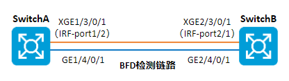
组网拓扑
某企业随着网络规模持续快速扩大,终端接入数量与业务数据流量急剧增长,现有核心交换机的包转发率、交换容量等转发性能已无法满足当前业务承载需求,存在带宽瓶颈、转发时延增大等问题;为保障网络稳定高效运行,需在充分利旧、保护现有网络投资的前提下,对核心层进行性能升级,增加一台设备搭建IRF实现核心冗余、负载,使整体网络转发能力提升一倍,同时优化网络架构,实现设备集中管控、故障快速定位,满足网络易管理、易维护、高可靠、可平滑扩展的使用要求。
配置思路
两台设备IRF堆叠,配置思路如下:
-
在独立运行模式下,完成 IRF 端口和参数的配置。
-
切换到 IRF 模式,在设备重启过程中,连接IRF物理接口。设备启动完成,IRF 搭建成功。
-
配置 MAD 检测。
配置步骤
**注意事项:**如果您采用先将设备切换到 IRF 模式,再绑定 IRF 端口的方式搭建 IRF。请在完成 IRF 端口等参数配置后,执行 save 命令保存当前配置,再执行 irf-port-configuration active 命令手工激活 IRF 端口的配置,才能形成 IRF!
步骤 1 Switch A IRF堆叠配置。
-
设置 Device A 的成员编号为1、优先级为32使其成为主设备,创建 IRF 端口 1/2,并将它与物理端口 Ten-GigabitEthernet3/0/1绑定。
[Switch A] irf member 1
[Switch A] irf priority 32
[Switch A] irf-port 1/2
[Switch A-irf-port2] port group interface ten-gigabitethernet 3/0/1
[Switch A-irf-port2] quit -
保存当前设备配置。
[Switch A] quit
save -
将设备的运行模式切换到 IRF 模式。
[Switch A] chassis convert mode irf
The device will switch to IRF mode and reboot. Continue? [Y/N]:y
You are recommended to save the current running configuration and specify the configuration
file for the next startup. Continue? [Y/N]:y
Please input the file name(*.cfg)[flash:/startup.cfg]
(To leave the existing filename unchanged, press the enter key):
flash:/startup.cfg exists, overwrite? [Y/N]:y
Validating file. Please wait...
Saved the current configuration to mainboard device successfully.
Do you want to convert the content of the next startup configuration file flash:
/startup.cfg to make it available in IRF mode? [Y/N]:y
Now rebooting, please wait... -
设备重启后 Switch A 组成了只有一台成员设备的 IRF。
步骤 2Switch B IRF堆叠配置。
-
配置Switch B的成员编号为 2,创建 IRF 端口 1/2,并将它与物理端口 Ten-GigabitEthernet3/0/1绑定。
system-view
[Switch B] irf member 2
[Switch B] irf-port 2/1
[Switch B-irf-port1] port group interface ten-gigabitethernet 3/0/1
[Switch B-irf-port1] quit -
保存当前设备配置。
[Switch B] quit
save -
将设备的运行模式切换到 IRF 模式。
system-view
[Switch B] chassis convert mode irf
The device will switch to IRF mode and reboot. Continue? [Y/N]:y
You are recommended to save the current running configuration and specify the configuration
file for the next startup. Continue? [Y/N]:y
Please input the file name(*.cfg)[flash:/startup.cfg]
(To leave the existing filename unchanged, press the enter key):
flash:/startup.cfg exists, overwrite? [Y/N]:y
Validating file. Please wait...
Saved the current configuration to mainboard device successfully.
Do you want to convert the content of the next startup configuration file flash:
/startup.cfg to make it available in IRF mode? [Y/N]:y
Now rebooting, please wait... -
设备 B 重启后与设备 A 形成 IRF,设备A为主设备,设备B为从设备。
步骤 3BFD MAD检测配置。
-
修改 IRF 链路 down 延迟上报时间为 0。
system-view
[Switch A] irf link-delay 0 -
创建 VLAN 3,并将 Switch A(成员编号为 1)上的端口和Switch B(成员编号为 2)上的端口 加入 VLAN 中。
[Switch A] vlan 3
[Switch A-vlan3] port gigabitethernet 1/4/0/1 gigabitethernet 2/4/0/1
[Switch A-vlan3] quit -
创建 VLAN 接口 3,并配置 MAD IP 地址。
[Switch A] interface vlan-interface 3
[Switch A-Vlan-interface3] mad bfd enable
[Switch A-Vlan-interface3] mad ip address 192.168.2.1 24 member 1
[Switch A-Vlan-interface3] mad ip address 192.168.2.2 24 member 2
[Switch A-Vlan-interface3] quit -
因为 BFD MAD 和生成树功能互斥,所以在接口上关闭生成树协议。
[Switch A] interface gigabitethernet 1/4/0/1
[Switch A-gigabitethernet-1/4/0/1] undo stp enable
[Switch A-gigabitethernet-1/4/0/1] quit
[Switch A] interface gigabitethernet 2/4/0/1
[Switch A-gigabitethernet-2/4/0/1] undo stp enable
步骤 4完成上述配置后,查看IRF堆叠配置情况。
display irf                    //查看所有成员设备的相关信息
display irf link               //查看IRF链路信息
display irf configuration      //查看成员编号
display bfd session            //查看BFD状态
display mad verbose            //查看MAD配置信息