目录
[1. 概述](#1. 概述)
[2. 绘图函数](#2. 绘图函数)
[3. 使用举例](#3. 使用举例)
[3.1 arrowedLine](#3.1 arrowedLine)
[3.2 circle](#3.2 circle)
[3.3 clipLine](#3.3 clipLine)
[3.4 drawContour](#3.4 drawContour)
[3.5 drawMarker](#3.5 drawMarker)
[3.6 ellipse](#3.6 ellipse)
[3.7 ellipse2Poly](#3.7 ellipse2Poly)
[3.8 fillConvexPoly](#3.8 fillConvexPoly)
[3.9 fillPoly](#3.9 fillPoly)
[3.10 getFontScaleFromHeight](#3.10 getFontScaleFromHeight)
[3.11 getTextSize](#3.11 getTextSize)
[3.12 line](#3.12 line)
[3.13 polylines](#3.13 polylines)
[3.14 putText](#3.14 putText)
[3.15 rectangle](#3.15 rectangle)
1. 概述
绘图函数可处理任意深度的矩阵/图像。形状边界可使用抗锯齿渲染(目前仅支持 8 位图像 )。所有函数都包含一个名为 color 的参数,该参数对于彩色图像使用 RGB 值(可使用Scalar构造函数创建),对于灰度图像使用亮度值。对于彩色图像,通道顺序通常为蓝(Blue)、绿(Green)、红(Red) 。Imshow ,imread 和 imwrite 函数均遵循此顺序。因此,如果你使用Scalar构造函数创建颜色,其格式应如下所示:
Scalar( blue_component , green_component , red_component , alpha_component)
如果你使用的是自定义的图像渲染和 I/O 函数,则可以使用任意的通道顺序。 绘图函数会独立处理每一个通道,既不依赖于通道顺序,甚至也不依赖于所使用的色彩空间。你可以使用 cvtColor 函数将整幅图像从 BGR 转换为 RGB,或转换为其他色彩空间。
如果绘制的图形部分或全部超出图像范围,绘图函数会对其进行裁剪 。此外,许多绘图函数可以处理以亚像素 (sub-pixel)精度指定的像素坐标。这意味着坐标可以作为定点数传递,并以整数形式编码。小数位数由移位参数指定,实际的点坐标计算如下:
该功能在渲染抗锯齿形状时特别有效。
当目标图像为 4 通道时,这些函数不支持 α 透明度。在这种情况下,颜色会被简单地复制到重绘的像素。因此,如果要绘制半透明形状,可以将其绘制在单独的缓冲区中,然后再与主图像混合。
2. 绘图函数
|------------------------|-----------------------|
| 函数 | 说明 |
| arrowedLine | 画一个从第一点指向第二点的箭头。 |
| circle | 画一个圆 |
| clipLine | 将线条裁剪到图像矩形框内。 |
| drawContour | 绘制轮廓线或填充轮廓线。 |
| drawMarker | 在图像中预先设定的位置绘制标记。 |
| ellipse | 绘制简单或粗椭圆弧,或填充椭圆扇形。 |
| ellipse2Poly | 用折线近似椭圆弧。 |
| fillConvexPoly | 填充凸多边形。 |
| fillPoly | 填充由一个或多个多边形围成的区域 |
| getFontScaleFromHeight | 计算达到给定像素高度所需的字体尺寸。 |
| getTextSize | 计算文本字符串的高度和宽度 |
| line | 绘制连接两点的一条线段 |
| polylines | 绘制若干条折线 |
| putText | 绘制文本字符串 |
| rectangle | 绘制一个简单的、粗线条的或实心的直立矩形。 |
3. 使用举例
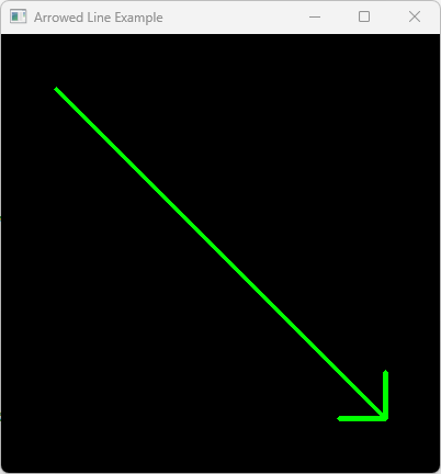
3.1 arrowedLine
#include <opencv2/opencv.hpp>
using namespace cv;
int Test_arrowedLine()
{
// 1. 创建一幅 400x400 黑色图像 (3 通道, 8位)
Mat img = Mat::zeros(400, 400, CV_8UC3);
// 2. 定义箭头起止点
Point start_point(50, 50);
Point end_point(350, 350);
// 3. 绘制箭头
// 参数: img, pt1, pt2, color, thickness, line_type, shift, tipLength
arrowedLine(img,
start_point,
end_point,
Scalar(0, 255, 0), // 绿色 (BGR)
3, // 厚道
8, // 线型 (8连通)
0, // 平衡
0.1); // 箭尖长度(占箭身全长的比例)
// 4. 显示结果
imshow("Arrowed Line Example", img);
waitKey(0); // Wait for a key press to close
return 0;
}
运行结果:
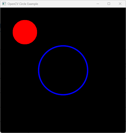
3.2 circle
#include <opencv2/opencv.hpp>
#include <iostream>
int Test_circle()
{
// 1. 创建一幅黑色图像 (512x512, 3 通道)
Mat image = Mat::zeros(512, 512, CV_8UC3);
// 2. 定义圆之参数
Point center(256, 256);
int radius = 100;
Scalar blue(255, 0, 0);
Scalar red(0, 0, 255);
// 3. 画一个蓝色的圆形轮廓(thickness = 3)
// circle(img, center, radius, color, thickness, lineType)
circle(image, center, radius, blue, 3, LINE_AA);
// 4. 画一个红色填充的小圆 (thickness = FILLED or -1)
circle(image, Point(100, 100), 50, red, FILLED);
// 5.显示结果
imshow("OpenCV Circle Example", image);
waitKey(0);
return 0;
}
运行结果:
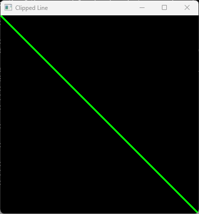
3.3 clipLine
int Test_clipLine()
{
// 1. 定义裁剪区域(图像尺寸或具体矩形)
cv::Size imgSize(400, 400);
cv::Rect imgRect(0, 0, 400, 400);
// 2. 定义一条起/止于边界之外的线段
cv::Point pt1(-50, -50);
cv::Point pt2(500, 500);
// 3. 为了便于可视创建一幅黑色图像
cv::Mat image = cv::Mat::zeros(imgSize, CV_8UC3);
// 4. 裁剪线段
// The points pt1 and pt2 are modified IN-PLACE to their clipped coordinates
bool isVisible = cv::clipLine(imgSize, pt1, pt2);
if (isVisible) {
// Draw the clipped line on the image
cv::line(image, pt1, pt2, cv::Scalar(0, 255, 0), 2);
std::cout << "Clipped Points: " << pt1 << " to " << pt2 << std::endl;
}
else {
std::cout << "The line is completely outside the boundary." << std::endl;
}
cv::imshow("Clipped Line", image);
cv::waitKey(0);
return 0;
}
运行结果:
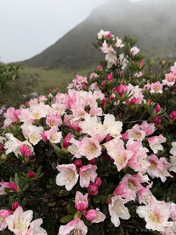
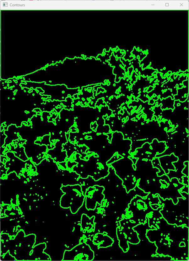
3.4 drawContour
int Test_drawContour()
{
// 1. 载入一幅图像并转换为恢度图像
cv::Mat src = cv::imread("D:\\TestVideo\\Flower4.jpg");
cv::Mat gray, binary;
cv::cvtColor(src, gray, cv::COLOR_BGR2GRAY);
// 2.转换为二值图像(在黑色背景上的白色物体中查找轮廓)
cv::threshold(gray, binary, 100, 255, cv::THRESH_BINARY);
// 3. 找查轮廓
std::vector<std::vector<cv::Point>> contours;
std::vector<cv::Vec4i> hierarchy;
cv::findContours(binary, contours, hierarchy, cv::RETR_TREE, cv::CHAIN_APPROX_SIMPLE);
// 4. 创建一个用于绘图的空白黑色图像。
cv::Mat drawing = cv::Mat::zeros(binary.size(), CV_8UC3);
// 5. 绘制轮廓
// -1 draws ALL contours; (0, 255, 0) is Green; 2 is thickness
cv::drawContours(drawing, contours, -1, cv::Scalar(0, 255, 0), 2);
// 绘制并填充特定轮廓(例如,第一个)
if (!contours.empty()) {
cv::drawContours(drawing, contours, 0, cv::Scalar(255, 0, 0), cv::FILLED);
}
cv::imshow("Contours", drawing);
cv::waitKey(0);
return 0;
}
下面是原图像和运行结果:
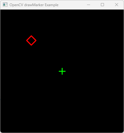
3 .5 drawMarker
int Test_drawMarker()
{
// 创建一幅 400x400 黑色图像
Mat img = Mat::zeros(400, 400, CV_8UC3);
// 定义标记属性
Point position(200, 200); // 图像中心
Scalar color(0, 255, 0); //绿色 (BGR)
int markerType = MARKER_CROSS; // 预定义标记类型
int markerSize = 20; // 像素中的标记大小
int thickness = 2; // 线厚度
// 绘制一个绿色十字标记。
drawMarker(img, position, color, markerType, markerSize, thickness);
// 绘制另一个标记(红色菱形)的示例
drawMarker(img, Point(100, 100), Scalar(0, 0, 255), MARKER_DIAMOND, 30, 2);
// 显示结果
imshow("OpenCV drawMarker Example", img);
waitKey(0);
return 0;
}
运行结果:
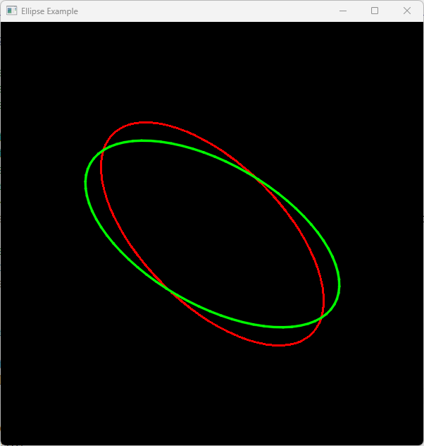
3 .6 ellipse
int Test_ellipse()
{
// 创建一幅黑色图像 (600x600)
cv::Mat img = cv::Mat::zeros(600, 600, CV_8UC3);
// Parameters:
// 1. Image
// 2. Center point (x, y)
// 3. Axes lengths (half-major axis, half-minor axis)
// 4. Rotation angle (degrees)
// 5. Start angle of arc (degrees)
// 6. End angle of arc (degrees)
// 7. Color (B, G, R)
// 8. Thickness (use -1 or cv::FILLED for a filled ellipse)
cv::ellipse(img, cv::Point(300, 300), cv::Size(200, 100), 45, 0, 360, cv::Scalar(0, 0, 255), 2);
// Define an ellipse using a RotatedRect (center, size, angle)
cv::RotatedRect box(cv::Point2f(300, 300), cv::Size2f(400, 200), 30);
cv::ellipse(img, box, cv::Scalar(0, 255, 0), 2, cv::LINE_AA);
std::vector<cv::Point> points; // Suppose these are contour points
if (points.size() >= 5) { // fitEllipse requires at least 5 points
cv::RotatedRect fittedEllipse = cv::fitEllipse(points);
cv::ellipse(img, fittedEllipse, cv::Scalar(0, 0, 255), 2);
}
cv::imshow("Ellipse Example", img);
cv::waitKey(0);
return 0;
}
运行结果:
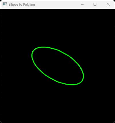
3 .7 ellipse2Poly
int Test_ellipse2Poly()
{
// 创建一幅黑色图像
cv::Mat image = cv::Mat::zeros(400, 400, CV_8UC3);
// 绘制椭圆的参数
cv::Point center(200, 200);
cv::Size axes(100, 50);
int angle = 30; // Rotation angle of the ellipse
int arcStart = 0; // Starting angle of the arc
int arcEnd = 360; // Ending angle of the arc (360 for full ellipse)
int delta = 5; // Angle between subsequent polyline vertices
// 存储最终的点
std::vector<cv::Point> pts;
// 根据椭圆定义生成折线点
cv::ellipse2Poly(center, axes, angle, arcStart, arcEnd, delta, pts);
// 在图上绘制折线
// Note: polylines() expects a vector of vectors or an array of points
std::vector<std::vector<cv::Point>> polylines_pts = { pts };
cv::polylines(image, polylines_pts, true, cv::Scalar(0, 255, 0), 2, cv::LINE_AA);
// Display the result
cv::imshow("Ellipse to Polyline", image);
cv::waitKey(0);
return 0;
}
运行结果:
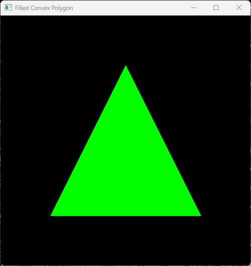
3 .8 fillConvexPoly
int Test_fillConvexPoly()
{
// 1. 创建一幅黑色图像 (500x500)
cv::Mat image = cv::Mat::zeros(500, 500, CV_8UC3);
// 2. 定义凸多边形顶点 (例如., 一个三角形)
// 点必须按顺序排列在周长上。
std::vector<cv::Point> points;
points.push_back(cv::Point(250, 100)); // 顶部
points.push_back(cv::Point(400, 400)); // 底部右角
points.push_back(cv::Point(100, 400)); // 底部左角
// 3. 填充凸多边形
// Parameters: (target_image, points_vector, color, line_type, shift)
cv::fillConvexPoly(image,
points,
cv::Scalar(0, 255, 0), // Green color (BGR)
cv::LINE_AA, // 抗锯齿线条
0); // 平移
// 4. Display the result
cv::imshow("Filled Convex Polygon", image);
cv::waitKey(0);
return 0;
}
运行结果:
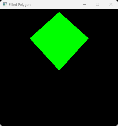
3 .9 fillPoly
int Test_fillPoly()
{
// 1. 创建一幅黑色图像 (400x400)
cv::Mat image = cv::Mat::zeros(400, 400, CV_8UC3);
//// 2. 定义一个三角形之顶点
//std::vector<cv::Point> triangle;
//triangle.push_back(cv::Point(200, 50));
//triangle.push_back(cv::Point(350, 350));
//triangle.push_back(cv::Point(50, 350));
//// 2. 定义一个不规则四边形之顶点
std::vector<cv::Point> quadrangle;
quadrangle.push_back(cv::Point(200, 10));
quadrangle.push_back(cv::Point(300, 100));
quadrangle.push_back(cv::Point(200, 210));
quadrangle.push_back(cv::Point(100, 100));
// 3. fillPoly 期望接收一个多边形列表(即向量的向量)。
std::vector<std::vector<cv::Point>> pts;
pts.push_back(quadrangle);
// 4. 绘制填充多边形
// Parameters: image, points, color (BGR), lineType
cv::fillPoly(image, pts, cv::Scalar(0, 255, 0), cv::LINE_8);
// 5. Display the result
cv::imshow("Filled Polygon", image);
cv::waitKey(0);
return 0;
}
运行结果:
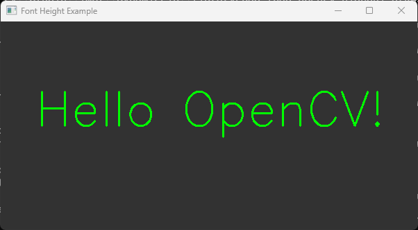
3.10getFontScaleFromHeight
int Test_getFontScaleFromHeight()
{
// 1. 创建一幅黑色图像
cv::Mat image = cv::Mat::zeros(300, 600, CV_8UC3);
image.setTo(cv::Scalar(50, 50, 50)); // 深灰色背景
std::string text = "Hello OpenCV!";
int fontFace = cv::FONT_HERSHEY_SIMPLEX;
int targetHeight = 50; // 像素中的目标高度
int thickness = 2;
cv::Point org(50, 150); // 源文本
cv::Scalar color(0, 255, 0); // 绿色
// 2. 计算目标高度对应的字体缩放比例
double fontScale = cv::getFontScaleFromHeight(fontFace, targetHeight, thickness);
std::cout << "Calculated Font Scale: " << fontScale << std::endl;
// 3. 以计算出的缩放比例渲染文本
cv::putText(image, text, org, fontFace, fontScale, color, thickness);
// 4. 验证高度(可选)
int baseLine = 0;
cv::Size textSize = cv::getTextSize(text, fontFace, fontScale, thickness, &baseLine);
std::cout << "Actual Text Height: " << textSize.height << "px" << std::endl;
cv::imshow("Font Height Example", image);
cv::waitKey(0);
return 0;
}
运行结果:
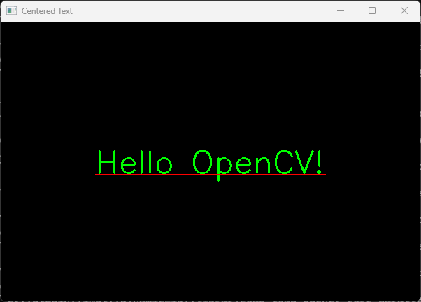
3.11 getTextSize
int Test_getTextSize()
{
// 1. Create a black image
cv::Mat img = cv::Mat::zeros(400, 600, CV_8UC3);
// 2. 定义文本属性
std::string text = "Hello OpenCV!";
int fontFace = cv::FONT_HERSHEY_SIMPLEX;
double fontScale = 1.5;
int thickness = 2;
int baseline = 0;
// 3. 计算文本大小
cv::Size textSize = cv::getTextSize(text, fontFace, fontScale, thickness, &baseline);
// 4. 计算文本中心的位置
// Center point (x) = (ImageWidth - TextWidth) / 2
// Center point (y) = (ImageHeight + TextHeight) / 2
cv::Point textOrg((img.cols - textSize.width) / 2,
(img.rows + textSize.height) / 2);
// 5. 绘制文本及外围框(可选)
cv::putText(img, text, textOrg, fontFace, fontScale, cv::Scalar(0, 255, 0), thickness);
// 绘制可视化基线
cv::line(img, textOrg + cv::Point(0, thickness),
textOrg + cv::Point(textSize.width, thickness), cv::Scalar(0, 0, 255));
cv::imshow("Centered Text", img);
cv::waitKey(0);
return 0;
}
运行结果:
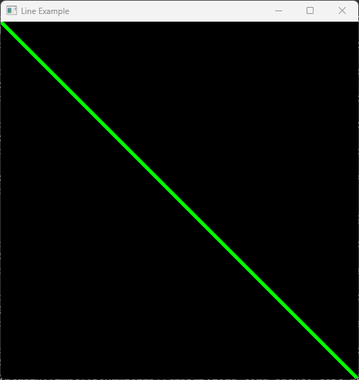
3.12 line
int Test_line()
{
// 1. Create a black image (512x512 pixels, 3-channel BGR)
cv::Mat image = cv::Mat::zeros(512, 512, CV_8UC3);
// 2. Define start and end points
cv::Point start(0, 0);
cv::Point end(511, 511);
// 3. Draw the line
// Parameters: (image, start, end, color, thickness, lineType)
cv::line(image, start, end, cv::Scalar(0, 255, 0), 3, cv::LINE_AA);
// 4. Display the result
cv::imshow("Line Example", image);
cv::waitKey(0); // Wait for a key press
return 0;
}
运行结果:
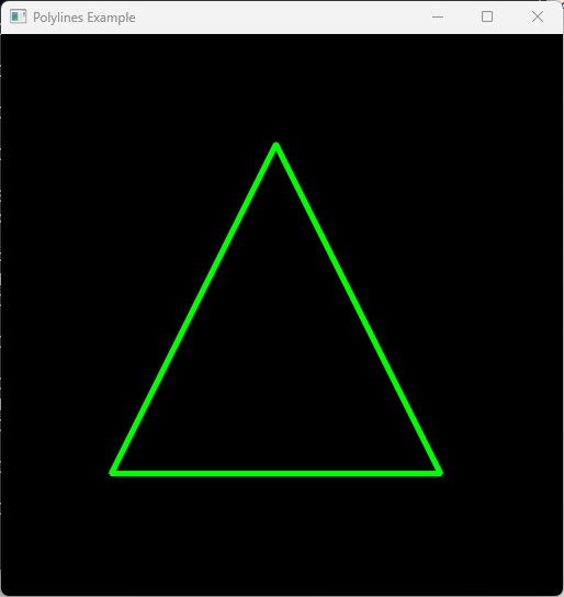
3.13 polylines
int Test_polylines()
{
// 1. Create a black image (512x512 pixels, 3 color channels)
cv::Mat image = cv::Mat::zeros(512, 512, CV_8UC3);
// 2. Define the vertices of the polygon
std::vector<cv::Point> pts;
pts.push_back(cv::Point(250, 100));
pts.push_back(cv::Point(400, 400));
pts.push_back(cv::Point(100, 400));
// 3. polylines expects an InputArrayOfArrays (a vector of vectors)
std::vector<std::vector<cv::Point>> polylines_pts;
polylines_pts.push_back(pts);
// 4. Draw the polyline
// Parameters: image, points, isClosed=true, color=Green(0,255,0), thickness=3
cv::polylines(image, polylines_pts, true, cv::Scalar(0, 255, 0), 3, cv::LINE_AA);
// 5. Display the result
cv::imshow("Polylines Example", image);
cv::waitKey(0);
return 0;
}
运行结果:
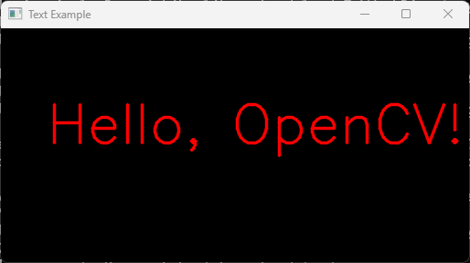
3.14 putText
int Test_putText()
{
// Create a 512x512 black image (3 channels)
cv::Mat img = cv::Mat::zeros(256, 512, CV_8UC3);
// Text properties
std::string text = "Hello, OpenCV!";
cv::Point position(50, 125); // Bottom-left corner of the text
int fontFace = cv::FONT_HERSHEY_SIMPLEX;
double fontScale = 2.0;
cv::Scalar color(0, 0, 255); // Blue in BGR
int thickness = 2;
// Write text on the image
cv::putText(img, text, position, fontFace, fontScale, color, thickness, cv::LINE_AA);
// Display the result
cv::imshow("Text Example", img);
cv::waitKey(0);
return 0;
}
运行结果:
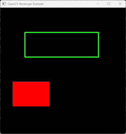
3.15 rectangle
int Test_rectangle()
{
// 1. Create a black image (512x512 pixels, 3 color channels)
cv::Mat image = cv::Mat::zeros(512, 512, CV_8UC3);
// 2. Define rectangle using two points (Top-Left and Bottom-Right)
// Draws a green rectangle with a thickness of 3 pixels
cv::Point pt1(100, 100);
cv::Point pt2(400, 200);
cv::rectangle(image, pt1, pt2, cv::Scalar(0, 255, 0), 3);
// 3. Define rectangle using cv::Rect(x, y, width, height)
// Draws a filled red rectangle (thickness = -1 or FILLED)
cv::Rect myRect(50, 300, 150, 100);
cv::rectangle(image, myRect, cv::Scalar(0, 0, 255), cv::FILLED);
// 4. Display the result
cv::imshow("OpenCV Rectangle Example", image);
cv::waitKey(0); // Wait for a key press
return 0;
}
运行结果: