一、前言
IRF是 H3C 自主研发的软件虚拟化技术,IRF2是横向虚拟化。它的核心思想是将多台设备连接在一起,进行必要的配置后,虚拟化成一台设备。使用这种虚拟化技术可以集合多台设备的硬件资源和软件处理能力,实现多台设备的协同工作、统一管理和不间断维护。
为便于描述,文中将虚拟设备统称为 IRF。因此本文中 IRF 包含两层含义:一是指 IRF 堆叠技术本身,二是指由 IRF 技术构建而成的虚拟设备。
二、IRF堆叠配置
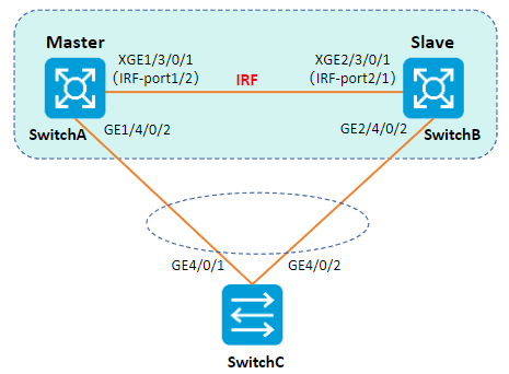
组网拓扑
企业网络规模迅速扩大,当前核心交换机转发能力已经不能满足需求,现需要在保护现有投资的基础上将网络转发能力提高一倍,并要求网络易管理、易维护。
- 为了将SwitchA的转发能力提高一倍,需要另外增加一台设备SwitchB。即在SwitchA 和SwitchB上配置 IRF 功能。
- 为了防止万一 IRF 链路故障导致 IRF 分裂、网络中存在两个配置冲突的 IRF,需要启用 MAD检测功能。采用 LACP MAD 检测方式来监测 IRF 的状态。
配置思路
两台框式交换机IRF堆叠,配置思路如下:
-
在独立运行模式下,完成 IRF配置。
-
启动 IRF 模式,连接 IRF 物理接口。
-
配置 MAD 检测功能。
配置步骤
注意事项: 如果采用先将设备切换到 IRF 模式,再绑定 IRF 端口的方式搭建 IRF。请在完成 IRF 端口等参数配置后,执行save命令保存当前配置,再执行 irf-port-configuration active 命令手工激活 IRF 端口的配置,才能形成 IRF。
步骤 1SwitchA IRF堆叠配置。
-
配置 SwitchA 的成员编号为1、优先级为32,创建 IRF 端口 1/2,加入物理端口。
[SwitchA] irf member 1
[SwitchA] irf priority 32
[SwitchA] irf-port 1/2
[SwitchA-irf-port2] port group interface ten-gigabitethernet 3/0/1
[SwitchA-irf-port2] quit -
将当前配置保存到下次启动配置文件。
[SwitchA] quit
save -
设备的运行模式切换到 IRF 模式。
system-view
[Sysname] chassis convert mode irf
The device will switch to IRF mode and reboot. Continue? [Y/N]:y
You are recommended to save the current running configuration and specify the configuration
file for the next startup. Continue? [Y/N]:y
Please input the file name(*.cfg)[flash:/startup.cfg]
(To leave the existing filename unchanged, press the enter key):
flash:/startup.cfg exists, overwrite? [Y/N]:y
Validating file. Please wait...
Saved the current configuration to mainboard device successfully.
Do you want to convert the content of the next startup configuration file flash:
/startup.cfg to make it available in IRF mode? [Y/N]:y
Now rebooting, please wait... -
设备重启后SwitchA组成了只有一台成员设备的 IRF。
步骤 2SwitchB IRF堆叠配置。
-
配置SwitchB 的成员编号为 2,创建 IRF 端口1/2,加入物理端口。
[SwitchB] irf member 2
[SwitchB] irf-port 2/1
[SwitchB-irf-port1] port group interface ten-gigabitethernet 3/0/1
[SwitchB-irf-port1] quit -
将当前配置保存到下次启动配置文件。
[SwitchB] quit
save -
将设备的运行模式切换到 IRF 模式。
system-view
[SwitchB] chassis convert mode irf
The device will switch to IRF mode and reboot. Continue? [Y/N]:y
You are recommended to save the current running configuration and specify the configuration
file for the next startup. Continue? [Y/N]:y
Please input the file name(*.cfg)[flash:/startup.cfg]
(To leave the existing filename unchanged, press the enter key):
flash:/startup.cfg exists, overwrite? [Y/N]:y
Validating file. Please wait...
Saved the current configuration to mainboard device successfully.
Do you want to convert the content of the next startup configuration file flash:
/startup.cfg to make it available in IRF mode? [Y/N]:y
Now rebooting, please wait... -
设备 B 重启后与设备 A 形成 IRF。
步骤 3LACP MAD配置。
-
核心交换机SwitchA创建一个动态聚合接口,并开启 LACP MAD 检测功能,并在聚合接口中添加成员端口,用于 SwitchA 和 SwitchB 实现 LACP MAD 检测。
[SwitchA] interface bridge-aggregation 2
[SwitchA-Bridge-Aggregation2] link-aggregation mode dynamic
[SwitchA-Bridge-Aggregation2] mad enable
You need to assign a domain ID (range: 0-4294967295)
[Current domain ID is: 1]:
The assigned domain ID is: 1
[SwitchA-Bridge-Aggregation2] quit
[SwitchA] interface gigabitethernet 1/4/0/2
[SwitchA-GigabitEthernet1/4/0/2] port link-aggregation group 2
[SwitchA-GigabitEthernet1/4/0/2] quit
[SwitchA] interface gigabitethernet 2/4/0/2
[SwitchA-GigabitEthernet2/4/0/2] port link-aggregation group 2 -
接入交换机SwitchC创建一个动态聚合接口,并在聚合接口中添加成员端口,用于LACP MAD检测。
[SwitchC] interface bridge-aggregation 2
[SwitchC-Bridge-Aggregation2] link-aggregation mode dynamic
[SwitchC-Bridge-Aggregation2] quit
[SwitchC] interface gigabitethernet 4/0/1
[SwitchC-GigabitEthernet4/0/1] port link-aggregation group 2
[SwitchC-GigabitEthernet4/0/1] quit
[SwitchC] interface gigabitethernet 4/0/2
[SwitchC-GigabitEthernet4/0/2] port link-aggregation group 2
步骤 4完成上述配置后,查看IRF堆叠配置情况。
display irf                                //查看所有成员设备的相关信息
display irf link                           //查看IRF链路信息
display irf configuration                  //查看成员编号
display mad verbose                        //查看MAD配置信息