文章目录
- [第一章 概述](#第一章 概述)
-
- [1.1 什么是 CameraInfo](#1.1 什么是 CameraInfo)
- [1.2 CameraInfo的核心价值](#1.2 CameraInfo的核心价值)
- [1.3 CameraInfo 与图像话题的关系](#1.3 CameraInfo 与图像话题的关系)
- [1.4 CameraInfo 的典型数据流](#1.4 CameraInfo 的典型数据流)
- [1.5 支持的环境](#1.5 支持的环境)
- [第二章 CameraInfo 消息定义详解](#第二章 CameraInfo 消息定义详解)
-
- [2.1 完整消息定义](#2.1 完整消息定义)
- [2.2 RegionOfInterest 子消息定义](#2.2 RegionOfInterest 子消息定义)
- [2.3 所有字段汇总表](#2.3 所有字段汇总表)
- [2.4 实际数据示例](#2.4 实际数据示例)
- [第三章 相机模型理论基础](#第三章 相机模型理论基础)
-
- [3.1 针孔相机模型(Pinhole Camera Model)](#3.1 针孔相机模型(Pinhole Camera Model))
-
- [3.1.1 坐标系定义](#3.1.1 坐标系定义)
- [3.1.2 投影过程](#3.1.2 投影过程)
- [3.1.3 内参矩阵 K 详解](#3.1.3 内参矩阵 K 详解)
- [3.1.4 反投影(像素 → 三维射线)](#3.1.4 反投影(像素 → 三维射线))
- [3.2 相机外参](#3.2 相机外参)
- [3.3 深度与视差的关系](#3.3 深度与视差的关系)
- [第四章 畸变模型深度解析](#第四章 畸变模型深度解析)
-
- [4.1 为什么需要畸变模型](#4.1 为什么需要畸变模型)
- [4.2 畸变的类型](#4.2 畸变的类型)
-
- [4.2.1 径向畸变(Radial Distortion)](#4.2.1 径向畸变(Radial Distortion))
- [4.2.2 切向畸变(Tangential Distortion)](#4.2.2 切向畸变(Tangential Distortion))
- [4.3 ROS 中支持的畸变模型](#4.3 ROS 中支持的畸变模型)
-
- [4.3.1 plumb_bob(钉形模型)](#4.3.1 plumb_bob(钉形模型))
- [4.3.2 rational_polynomial(有理多项式模型)](#4.3.2 rational_polynomial(有理多项式模型))
- [4.3.3 equidistant(等距投影模型)](#4.3.3 equidistant(等距投影模型))
- [4.3.4 kannala_brandt(Kannala-Brandt 模型)](#4.3.4 kannala_brandt(Kannala-Brandt 模型))
- [4.3.5 fisheye62](#4.3.5 fisheye62)
- [4.4 畸变模型对比总结](#4.4 畸变模型对比总结)
- [4.5 去畸变(Undistortion)](#4.5 去畸变(Undistortion))
- [第五章 四大核心矩阵 (D/K/R/P)](#第五章 四大核心矩阵 (D/K/R/P))
-
- [5.1 D 矩阵:畸变系数](#5.1 D 矩阵:畸变系数)
-
- [5.1.1 定义](#5.1.1 定义)
- [5.1.2 plumb_bob 模型下的 D 矩阵](#5.1.2 plumb_bob 模型下的 D 矩阵)
- [5.1.3 畸变系数的物理意义](#5.1.3 畸变系数的物理意义)
- [5.1.4 数值示例](#5.1.4 数值示例)
- [5.2 K 矩阵:相机内参矩阵](#5.2 K 矩阵:相机内参矩阵)
-
- [5.2.1 定义](#5.2.1 定义)
- [5.2.2 参数详解](#5.2.2 参数详解)
- [5.2.3 焦距与视场角的关系](#5.2.3 焦距与视场角的关系)
- [5.2.4 数值示例](#5.2.4 数值示例)
- [5.3 R 矩阵:校正矩阵](#5.3 R 矩阵:校正矩阵)
-
- [5.3.1 定义](#5.3.1 定义)
- [5.3.2 作用](#5.3.2 作用)
- [5.3.3 单目 vs 双目](#5.3.3 单目 vs 双目)
- [5.3.4 立体校正的几何意义](#5.3.4 立体校正的几何意义)
- [5.3.5 数值示例](#5.3.5 数值示例)
- [5.4 P 矩阵:投影矩阵](#5.4 P 矩阵:投影矩阵)
-
- [5.4.1 定义](#5.4.1 定义)
- [5.4.2 参数详解](#5.4.2 参数详解)
- [5.4.3 投影公式](#5.4.3 投影公式)
- [5.4.4 双目视差与深度的计算](#5.4.4 双目视差与深度的计算)
- [5.4.5 数值示例](#5.4.5 数值示例)
- [5.5 矩阵之间的关系总结](#5.5 矩阵之间的关系总结)
- [第六章 相机标定实战](#第六章 相机标定实战)
-
- [6.1 标定的目的与意义](#6.1 标定的目的与意义)
- [6.2 标定工具](#6.2 标定工具)
- [6.3 标定材料准备](#6.3 标定材料准备)
-
- [6.3.1 标定板选择](#6.3.1 标定板选择)
- [6.4 完整标定流程](#6.4 完整标定流程)
-
- [步骤 1:安装标定工具包](#步骤 1:安装标定工具包)
- [步骤 2:启动相机并确认话题](#步骤 2:启动相机并确认话题)
- [步骤 3:运行标定程序](#步骤 3:运行标定程序)
- [步骤 4:采集标定数据](#步骤 4:采集标定数据)
- [步骤 5:执行标定与保存](#步骤 5:执行标定与保存)
- [步骤 6:提取标定结果](#步骤 6:提取标定结果)
- [6.5 标定结果文件格式](#6.5 标定结果文件格式)
- [6.6 在 ROS 中加载标定文件](#6.6 在 ROS 中加载标定文件)
-
- [方法一:通过 camera_info_manager 加载](#方法一:通过 camera_info_manager 加载)
- [方法二:手动发布 CameraInfo](#方法二:手动发布 CameraInfo)
- [6.7 标定质量评估](#6.7 标定质量评估)
- [第七章 image_geometry 工具包](#第七章 image_geometry 工具包)
-
- [7.1 概述](#7.1 概述)
- [7.2 PinholeCameraModel(针孔相机模型)](#7.2 PinholeCameraModel(针孔相机模型))
-
- [7.2.1 核心 API 方法](#7.2.1 核心 API 方法)
- [7.2.2 C++ 使用示例](#7.2.2 C++ 使用示例)
- [7.2.3 Python 使用示例](#7.2.3 Python 使用示例)
- [7.3 StereoCameraModel(立体相机模型)](#7.3 StereoCameraModel(立体相机模型))
-
- [7.3.1 核心 API 方法](#7.3.1 核心 API 方法)
- [7.3.2 C++ 使用示例](#7.3.2 C++ 使用示例)
- [7.4 depth_image_proc 节点](#7.4 depth_image_proc 节点)
- [第八章 CameraInfo 在深度相机中的应用](#第八章 CameraInfo 在深度相机中的应用)
-
- [8.1 深度相机的CameraInfo话题](#8.1 深度相机的CameraInfo话题)
- [8.2 深度相机中的CameraInfo用途](#8.2 深度相机中的CameraInfo用途)
-
- [8.2.1 点云生成](#8.2.1 点云生成)
- [8.2.2 深度对齐(Depth-to-Color Alignment)](#8.2.2 深度对齐(Depth-to-Color Alignment))
- [8.2.3 深度图去畸变](#8.2.3 深度图去畸变)
- [8.3 RealSense D435 的CameraInfo示例](#8.3 RealSense D435 的CameraInfo示例)
- [8.4 配置深度相机的 CameraInfo](#8.4 配置深度相机的 CameraInfo)
- [第九章 CameraInfo 在立体视觉中的应用](#第九章 CameraInfo 在立体视觉中的应用)
-
- [9.1 立体视觉基本原理](#9.1 立体视觉基本原理)
- [9.2 双目相机的 CameraInfo 配置](#9.2 双目相机的 CameraInfo 配置)
- [9.3 立体视觉处理流水线](#9.3 立体视觉处理流水线)
- [9.4 视差图与点云](#9.4 视差图与点云)
- [9.5 使用ROS进行双目标定](#9.5 使用ROS进行双目标定)
- [第十章 编程实战](#第十章 编程实战)
-
- [10.1 实战一:自定义发布 CameraInfo](#10.1 实战一:自定义发布 CameraInfo)
- [10.2 实战二:订阅 CameraInfo 并进行坐标变换](#10.2 实战二:订阅 CameraInfo 并进行坐标变换)
- [10.3 实战三:深度图+CameraInfo→ 点云(手动实现)](#10.3 实战三:深度图+CameraInfo→ 点云(手动实现))
- [10.4 实战四:使用OpenCV+CameraInfo进行图像去畸变](#10.4 实战四:使用OpenCV+CameraInfo进行图像去畸变)
- [第十一章 常见问题与排错](#第十一章 常见问题与排错)
-
- [11.1 CameraInfo 参数问题](#11.1 CameraInfo 参数问题)
- [11.2 时钟同步问题](#11.2 时钟同步问题)
- [11.3 ROI 和Binning对参数的影响](#11.3 ROI 和Binning对参数的影响)
- [11.4 Gazebo 仿真中的 CameraInfo](#11.4 Gazebo 仿真中的 CameraInfo)
- [11.5 ROS1与ROS2 的差异](#11.5 ROS1与ROS2 的差异)
- [第十二章 附录](#第十二章 附录)
-
- [附录 A:CameraInfo 快速参考卡](#附录 A:CameraInfo 快速参考卡)
- [附录 B:常用命令速查](#附录 B:常用命令速查)
- [附录 C:相关 ROS 包列表](#附录 C:相关 ROS 包列表)
- [附录 D:参考文献](#附录 D:参考文献)
- 学习链接
第一章 概述
1.1 什么是 CameraInfo
在 ROS(Robot Operating System)生态中,sensor_msgs/CameraInfo 是传递相机校准信息的标准消息类型。它充当了相机硬件与上层视觉算法之间的"契约"------无论底层使用的是USB摄像头、Intel RealSense 深度相机,还是仿真环境中的虚拟相机,只要遵循CameraInfo消息规范,上层的图像处理、点云生成、三维重建等算法就能无缝衔接。
简而言之,CameraInfo 是ROS中相机标定参数的标准化载体 。它将相机的光学特性、几何参数、运行配置等信息打包成一个结构化的消息,通过 camera_info 话题以主题(Topic)的形式发布,供整个ROS系统中的其他节点订阅和使用。
1.2 CameraInfo的核心价值
CameraInfo在ROS视觉系统中具有以下核心价值:
-
标准化互通:不同厂商的相机具有不同的 SDK 和数据格式,CameraInfo 提供了一个统一的参数描述标准,使得上层算法无需关心底层硬件差异。
-
精确的几何计算:通过 CameraInfo 中包含的内参矩阵(K)、畸变系数(D)、投影矩阵§等参数,可以实现精确的 2D-3D 坐标转换、图像去畸变、立体匹配、点云生成等几何运算。
-
模块化设计 :CameraInfo 将图像数据和相机参数分离为独立的话题(
image_raw和camera_info),使得不同的处理节点,可以按需订阅参数,不必关心图像数据本身。 -
Sim-to-Real 一致性:在仿真(如Gazebo、Isaac Sim)和真实设备之间,CameraInfo 消息格式完全一致,极大地简化了从仿真到实物(Sim-to-Real)的迁移流程。
1.3 CameraInfo 与图像话题的关系
CameraInfo 消息应位于相机的命名空间下的 camera_info 话题上,并伴随以下图像话题共同工作:
| 图像话题 | 说明 |
|---|---|
image_raw |
相机驱动输出的原始数据,可能是 Bayer 编码 |
image |
单色图像,有畸变 |
image_color |
彩色图像,有畸变 |
image_rect |
单色图像,已校正(去畸变 + 立体校正) |
image_rect_color |
彩色图像,已校正 |
- 重要约定 :如果
K[0] == 0.0,则表示该相机未标定(uncalibrated)。客户端在使用 CameraInfo 参数之前应始终检查此标志,避免使用全零矩阵进行计算。
1.4 CameraInfo 的典型数据流
┌─────────────┐    image_raw      ┌──────────────┐    image_rect
│  Camera      │ ────────────────> │  image_proc   │ ────────────────>  下游节点
│  Driver      │                   │               │
│  Node        │ ────────────────> │               │ ────────────────>
└─────────────┘    camera_info      └──────────────┘    camera_info
     │                                      │
     │          depth/image_raw              │
     └─────────────────────────────────>  depth_image_proc
                                           ────────────────>  PointCloud2
1.5 支持的环境
CameraInfo作为ROS的核心消息之一,在以下版本中均有完整支持:
| ROS 版本 | 消息类型路径 |
|---|---|
| ROS1 Melodic | sensor_msgs/CameraInfo |
| ROS1 Noetic | sensor_msgs/CameraInfo |
| ROS2 Humble | sensor_msgs/msg/CameraInfo |
| ROS2 Iron | sensor_msgs/msg/CameraInfo |
| ROS2 Jazzy | sensor_msgs/msg/CameraInfo |
| ROS2 Rolling | sensor_msgs/msg/CameraInfo |
查看消息定义的命令:
bash
# ROS1
rosmsg show sensor_msgs/CameraInfo

# ROS2
ros2 interface show sensor_msgs/msg/CameraInfo
第二章 CameraInfo 消息定义详解
2.1 完整消息定义
以下是从 ROS 官方源码仓库中提取的 CameraInfo 消息完整定义(来自 sensor_msgs/msg/CameraInfo.msg):
cpp
# This message defines meta information for a camera. It should be in a
# camera namespace on topic "camera_info" and accompanied by up to five
# image topics named:
#
#   image_raw - raw data from the camera driver, possibly Bayer encoded
#   image            - monochrome, distorted
#   image_color      - color, distorted
#   image_rect       - monochrome, rectified
#   image_rect_color - color, rectified
#
# The message header is used to correlate the CameraInfo with the
# corresponding image data. The timestamp field in the header is used to
# indicate the time at which the image was captured.

std_msgs/Header header

# Image acquisition time and camera coordinate frame.
#   - timestamp:       Time at which the image was captured.
#   - frame_id:        Optical camera frame. The origin is at the optical
#                      center. +x points right, +y points down, +z points
#                      into the image plane.

# ===================== Calibration Parameters =====================

# These are fixed during camera calibration. Their values will be the same
# in all messages until the camera is recalibrated. They are used to
# transform raw (distorted) images to undistorted images (using D and K)
# or rectified images (using D, K, R).
uint32 height
uint32 width

# The distortion parameters, size based on the distortion model.
# For "plumb_bob", the 5 parameters are: (k1, k2, t1, t2, k3).
float64[] D

# Intrinsic camera matrix for the raw (distorted) images.
#     [fx  0  cx]
# K = [ 0 fy  cy]
#     [ 0  0   1]
# Projects 3D points in the camera frame to 2D pixel coordinates.
float64[9] K  # 3x3 row-major matrix

# Rectification matrix (stereo cameras only)
# A rotation matrix aligning the camera coordinate system to the ideal
# stereo image plane so that epipolar lines in both stereo images are
# parallel.
float64[9] R  # 3x3 row-major matrix

# Projection/camera matrix
#     [fx'  0  cx' Tx]
# P = [ 0  fy' cy' Ty]
#     [ 0   0   1   0]
# By convention, this matrix specifies the intrinsic (camera) matrix
# of the processed (rectified) image. That is, the left 3x3 portion
# is the normal intrinsic matrix for the rectified image.
# It projects 3D points in the camera frame to 2D pixel coordinates.
float64[12] P  # 3x4 row-major matrix

# The distortion model used. Supported models are listed in
# sensor_msgs/distortion_models.h. For most cameras, "plumb_bob" - a
# simple model of radial and tangential distortion - is sufficient.
string distortion_model

# ===================== Operational Parameters =====================

# These define the image region actually captured by the camera
# driver. Although they affect the geometry of the output image, they
# may be changed freely without recalibrating the camera.

# Binning: if the camera has 2x2 binning, the width and height of
# the output image are half of the raw image dimensions.
# A value of 0 is treated as 1 (no binning).
uint32 binning_x
uint32 binning_y

# Region of interest (subwindow of full camera resolution), given in
# full resolution (unbinned) image coordinates. A particular ROI
# always denotes the same window of pixels on the camera sensor,
# regardless of binning settings.
# The default setting of roi (all values 0) is considered the same as
# full resolution (roi.width = width, roi.height = height).
RegionOfInterest roi
2.2 RegionOfInterest 子消息定义
CameraInfo 中包含一个嵌套消息 RegionOfInterest,用于描述感兴趣区域:
cpp
# This message is used to specify a region of interest within an image.
uint32 x_offset  # Horizontal offset from top-left corner
uint32 y_offset  # Vertical offset from top-left corner
uint32 height    # Height of the ROI
uint32 width     # Width of the ROI
bool do_rectify # Should this ROI be rectified?
2.3 所有字段汇总表
| 字段名 | 类型 | 分类 | 说明 |
|---|---|---|---|
header |
Header |
图像信息 | 标准消息头,含时间戳和坐标系 ID |
header.stamp |
Time |
图像信息 | 图像采集时间 |
header.frame_id |
string |
图像信息 | 光学坐标系名称 |
height |
uint32 |
标定参数 | 标定图像高度(像素) |
width |
uint32 |
标定参数 | 标定图像宽度(像素) |
distortion_model |
string |
标定参数 | 畸变模型名称 |
D |
float64[] |
标定参数 | 畸变系数数组 |
K |
float64[9] |
标定参数 | 内参矩阵 (3×3) |
R |
float64[9] |
标定参数 | 校正矩阵 (3×3) |
P |
float64[12] |
标定参数 | 投影矩阵 (3×4) |
binning_x |
uint32 |
运行参数 | X 方向像素合并因子 |
binning_y |
uint32 |
运行参数 | Y 方向像素合并因子 |
roi.x_offset |
uint32 |
运行参数 | ROI 水平偏移 |
roi.y_offset |
uint32 |
运行参数 | ROI 垂直偏移 |
roi.height |
uint32 |
运行参数 | ROI 高度 |
roi.width |
uint32 |
运行参数 | ROI 宽度 |
roi.do_rectify |
bool |
运行参数 | 是否对 ROI 做校正 |
2.4 实际数据示例
以下是一个完整的CameraInfo消息示例(以YAML格式展示,常见于标定结果文件):
yaml
header:
  stamp:
    sec: 1622547801
    nanosec: 123456789
  frame_id: "camera_color_optical_frame"

height: 720
width: 1280
distortion_model: "plumb_bob"
D: [-0.102865, 0.173613, -0.001142, 0.005375, 0.000000]

K: [911.05362,   0.0,     651.73985,
      0.0,     906.6416,   351.74792,
      0.0,       0.0,       1.0]

R: [1.0, 0.0, 0.0,
    0.0, 1.0, 0.0,
    0.0, 0.0, 1.0]

P: [918.41508,   0.0,     660.15871,   0.0,
      0.0,     923.61282,   352.39286,   0.0,
      0.0,       0.0,         1.0,       0.0]

binning_x: 1
binning_y: 1
roi:
  x_offset: 0
  y_offset: 0
  height: 0
  width: 0
  do_rectify: false
第三章 相机模型理论基础
3.1 针孔相机模型(Pinhole Camera Model)
针孔相机模型是计算机视觉中最基础、最广泛使用的相机成像模型。它将相机抽象为一个理想的小孔(针孔),光线通过该小孔在成像平面上形成倒立的像。
3.1.1 坐标系定义
在ROS中,相机坐标系遵循以下约定(即 光学坐标系 Optical Frame):
| 轴 | 方向 | 说明 |
|---|---|---|
| X 轴 | 指向图像右侧 | 与图像水平方向一致 |
| Y 轴 | 指向图像下方 | 与图像垂直方向一致(注意:与数学坐标系相反) |
| Z 轴 | 指向前方(光轴方向) | 垂直于成像平面,指向场景 |
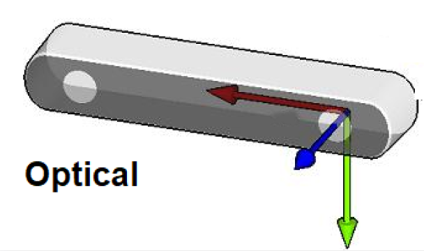
坐标系原点:位于相机的光学中心(Optical Center),即镜头的焦点位置。
3.1.2 投影过程
针孔相机模型描述了三维空间点到二维图像像素的投影关系。整个投影过程分为以下几个步骤:
- 步骤一:世界坐标系 → 相机坐标系
通过相机的外参(旋转矩阵 R_ext、平移向量 t_ext),将世界坐标系中的三维点 P_w 转换为相机坐标系中的 P_c:
cpp
P_c = R_ext × P_w + t_ext其中 R_ext 是 3×3 旋转矩阵,t_ext 是 3×1 平移向量。
- 步骤二:相机坐标系 → 归一化平面
将相机坐标系中的点 (X_c, Y_c, Z_c) 投影到归一化平面(假设焦距 f = 1):
cpp
x = X_c / Z_c
y = Y_c / Z_c- 步骤三:归一化平面 → 像素坐标
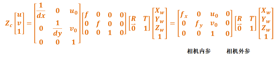
通过内参矩阵 K,将归一化坐标 (x, y) 转换为像素坐标 (u, v):
cpp
[u]   [fx  0  cx] [X_c]
[v] = [ 0 fy  cy] [Y_c]
[1]   [ 0  0   1] [Z_c]
其中:
fx、fy:焦距(以像素为单位),分别对应X和Y方向cx、cy:主点坐标(Principal Point),即光轴与成像平面交点的像素位置- 通常对于方形像素的相机,
fx ≈ fy
3.1.3 内参矩阵 K 详解
内参矩阵K是CameraInfo 中最核心的参数之一,完整形式为:
cpp
    ┌           ┐
    │ fx   0  cx │
K = │  0  fy  cy │
    │  0   0   1 │
└ ┘| 参数 | 物理含义 | 单位 | 典型范围 |
|---|---|---|---|
fx |
X 方向焦距 | 像素 | 数百到数千 |
fy |
Y 方向焦距 | 像素 | 数百到数千 |
cx |
主点 X 坐标 | 像素 | 约width/2 |
cy |
主点 Y 坐标 | 像素 | 约height/2 |
-
焦距的物理含义 :焦距越大,相机视角越窄(长焦),物体在图像中越大;焦距越小,视角越广(广角),物体在图像中越小。当
fx = fy时,像素是正方形的。 -
主点的物理含义:主点 (cx, cy) 是图像平面上的"中心点",理想情况下应在图像正中央。但由于制造工艺和装配误差,主点可能偏离中心。
3.1.4 反投影(像素 → 三维射线)
给定一个像素坐标 (u, v) 和已知的深度值 Z,可以反推出三维空间坐标:
cpp
X = (u - cx) × Z / fx
Y = (v - cy) × Z / fy
Z = Z(已知深度值)
如果深度Z未知,则像素 (u, v) 对应的是一条从光学中心出发、经过该像素的三维射线,可以用方向向量表示:
cpp
ray_x = (u - cx) / fx
ray_y = (v - cy) / fy
ray_z = 1.0
3.2 相机外参
相机外参描述了相机在世界坐标系中的位置和朝向,包括:
- 旋转矩阵 R:3×3 正交矩阵,描述相机坐标系的朝向
- 平移向量 t:3×1 向量,描述相机坐标系原点在世界坐标系中的位置
注意 :CameraInfo中的R矩阵是立体校正矩阵,不是外参旋转矩阵。相机外参通常通过TF(Transform)树来管理,而不是包含在CameraInfo 中。
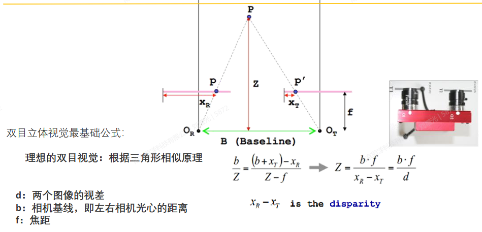
3.3 深度与视差的关系
在立体视觉中,视差(disparity)与深度(depth)的关系为:
cpp
depth = fx × baseline / disparity其中:
fx:相机焦距(像素单位),来自内参矩阵Kbaseline:两个相机光心之间的距离(基线)disparity:同一 3D点在左右图像中的水平像素差
这个公式直接体现了 CameraInfo 中 K 矩阵在深度计算中的关键作用。
第四章 畸变模型深度解析
4.1 为什么需要畸变模型
实际相机的镜头并非理想的针孔,光线穿过镜头时会发生折射,导致图像出现各种畸变。畸变不改变场景的结构,但会扭曲图像中物体的形状和位置。为了进行精确的几何计算,必须对畸变进行建模和校正。
4.2 畸变的类型
4.2.1 径向畸变(Radial Distortion)
径向畸变是由镜头形状引起的,光线离光轴越远,畸变越严重。
-
桶形畸变(Barrel Distortion):常见于广角镜头。图像中心区域被"压缩",边缘被"拉伸",使得直线变为向外弯曲的曲线。效果类似于将图像映射到球面上。
-
枕形畸变(Pincushion Distortion):常见于长焦镜头。图像边缘被"压缩",中心被"拉伸",使得直线变为向内弯曲的曲线。
径向畸变用以下多项式建模:
cpp
x_distorted = x × (1 + k1×r² + k2×r⁴ + k3×r⁶)
y_distorted = y × (1 + k1×r² + k2×r⁴ + k3×r⁶)
其中 r² = x² + y²,k1、k2、k3 是径向畸变系数。
4.2.2 切向畸变(Tangential Distortion)
切向畸变是由镜头与成像平面不完全平行引起的,主要来自制造和装配误差。
cpp
x_distorted += 2×t1×x×y + t2×(r² + 2×x²)
y_distorted += t1×(r² + 2×y²) + 2×t2×x×y
其中 t1(也称 p1)和 t2(也称 p2)是切向畸变系数。
原始网格          桶形畸变          枕形畸变
┌─────┐         ╱─────╲         ┌─────┐
│     │        ╱       ╲        │ ╲ ╱ │
│     │       │         │       │  ╳  │
│     │        ╲       ╱        │ ╱ ╲ │
└─────┘         ╲─────╱         └─────┘
              (广角镜头)        (长焦镜头)
4.3 ROS 中支持的畸变模型
ROS的CameraInfo 通过 distortion_model 字段指定使用的畸变模型,通过 D 字段存储相应的畸变系数。以下是ROS生态中常用的畸变模型:
4.3.1 plumb_bob(钉形模型)
- 来源:OpenCV标准Brown-Conrady 模型
- 参数数量:5 个
- 参数含义 :
D = [k1, k2, t1, t2, k3]k1、k2:低阶径向畸变系数t1、t2:切向畸变系数(也称 p1、p2)k3:高阶径向畸变系数
- 适用场景:大多数普通相机(USB 摄像头、工业相机等)
- 特点:最常用的畸变模型,足够描述绝大多数镜头的畸变
4.3.2 rational_polynomial(有理多项式模型)
- 来源:OpenCV有理多项式畸变模型
- 参数数量:8 个
- 参数含义 :
D = [k1, k2, p1, p2, k3, k4, k5, k6]- 前 5 个参数与 plumb_bob 相同
k4、k5、k6:额外的高阶径向畸变系数
- 适用场景:具有较大畸变的镜头(如鱼眼镜头改装为针孔模型时)
- 特点:相比 plumb_bob 增加了更多高阶项,可以更好地拟合复杂的畸变
4.3.3 equidistant(等距投影模型)
- 来源:OpenCV Fisheye 模块
- 参数数量:4 个
- 参数含义 :
D = [k1, k2, k3, k4]- 四个系数对应 Kannala-Brandt 模型的径向畸变
- 适用场景:鱼眼镜头(Fisheye Lens)
- 特点:专为鱼眼镜头设计,等距投影使得角度与图像距离成正比
4.3.4 kannala_brandt(Kannala-Brandt 模型)
- 参数数量:4 个
- 参数含义 :
D = [k1, k2, k3, k4] - 适用场景:鱼眼镜头
- 特点:与equidistant 等价,在 ROS2的Foxglove Studio等工具中被广泛使用
4.3.5 fisheye62
- 来源:Meta Project Aria 自定义模型
- 参数数量:最多7个
- 参数含义 :
D = [k0, k1, k2, k3, p0, p1, crit_theta](crit_theta 可选) - 适用场景:Meta Project Aria 等特殊设备
4.4 畸变模型对比总结
| 畸变模型 | 参数数量 | 镜头类型 | 精度 | ROS 支持度 |
|---|---|---|---|---|
plumb_bob |
5 | 标准/广角 | 中 | ★★★★★ |
rational_polynomial |
8 | 标准/广角 | 高 | ★★★★ |
equidistant |
4 | 鱼眼 | 高 | ★★★★ |
kannala_brandt |
4 | 鱼眼 | 高 | ★★★★ |
fisheye62 |
6-7 | 特殊鱼眼 | 高 | ★★ |
4.5 去畸变(Undistortion)
去畸变的目的是将畸变图像恢复为无畸变的理想图像。
ROS中去畸变的过程使用CameraInfo 中的 D(畸变系数)和 K(内参矩阵):
- 去畸变流程 :
1. 对于输出图像中的每个像素 (u_d, v_d)(去畸变坐标),使用内参矩阵 K_inv计算归一化坐标 (x, y)
2. 使用畸变模型和系数 D,计算对应的畸变归一化坐标 (x_d, y_d)
3. 使用内参矩阵 K,将 (x_d, y_d) 映射回原始(畸变)图像的像素坐标
4. 从原始图像中插值获取像素值,填充到输出图像中
这个过程的计算量较大,因此通常会预计算一个畸变映射表(remap table),然后通过查表快速完成去畸变。
第五章 四大核心矩阵 (D/K/R/P)
5.1 D 矩阵:畸变系数
5.1.1 定义
D是一个可变长度的浮点数数组,存储畸变模型的系数。其长度和含义取决于distortion_model 字段指定的畸变模型。
5.1.2 plumb_bob 模型下的 D 矩阵
cpp
D = [k1, k2, t1, t2, k3]| 索引 | 参数 | 类型 | 说明 | 典型值范围 |
|---|---|---|---|---|
| 0 | k1 | 径向畸变 | 主径向畸变系数 | -1.0 ~ 1.0 |
| 1 | k2 | 径向畸变 | 次径向畸变系数 | -1.0 ~ 1.0 |
| 2 | t1 (p1) | 切向畸变 | X 方向切向畸变 | -0.01 ~ 0.01 |
| 3 | t2 (p2) | 切向畸变 | Y 方向切向畸变 | -0.01 ~ 0.01 |
| 4 | k3 | 径向畸变 | 高阶径向畸变系数 | -0.01 ~ 0.01 |
5.1.3 畸变系数的物理意义
- k1:最主要的径向畸变系数。k1 < 0 对应桶形畸变,k1 > 0 对应枕形畸变
- k2:辅助径向畸变系数,用于描述更复杂的径向畸变
- t1, t2:切向畸变系数,通常数值很小(比径向畸变小 1-2 个数量级)
- k3:高阶径向畸变修正,用于提高拟合精度
5.1.4 数值示例
cpp
# 一个具有中等畸变的 USB 摄像头
D: [-0.102865, 0.173613, -0.001142, 0.005375, 0.0]

# 一个几乎无畸变的工业相机
D: [0.001, -0.0002, 0.00001, -0.00003, 0.0]

# 一个畸变较大的广角相机
D: [-0.35, 0.15, -0.003, 0.001, -0.28]
5.2 K 矩阵:相机内参矩阵
5.2.1 定义
K 是一个3×3 的行优先(row-major)浮点数矩阵,描述相机的内部光学特性。
cpp
K = [fx  0  cx]
    [ 0 fy  cy]
    [ 0  0   1]
5.2.2 参数详解
cpp
K[0] = fx    K[1] = 0     K[2] = cx
K[3] = 0     K[4] = fy    K[5] = cy
K[6] = 0 K[7] = 0 K[8] = 1| 参数 | 含义 | 物理意义 | 如何解读 |
|---|---|---|---|
fx |
X 方向焦距 | 像素单位 | 值越大视角越窄。例如 fx=600 表示约 60° 水平视场角(640 宽) |
fy |
Y 方向焦距 | 像素单位 | 通常接近 fx。若偏差大说明像素非正方形 |
cx |
主点 X | 像素 | 理想值 ≈ width/2。偏移说明光轴未对准图像中心 |
cy |
主点 Y | 像素 | 理想值 ≈ height/2 |
5.2.3 焦距与视场角的关系
对于水平视场角(HFOV):
cpp
HFOV = 2 × arctan(width / (2 × fx))例如,对于一个 640×480 的相机:
fx = 525→ HFOV ≈ 62°fx = 350→ HFOV ≈ 86°(广角)fx = 800→ HFOV ≈ 43°(窄视角)
5.2.4 数值示例
cpp
# 640x480 USB 摄像头
K: [614.175, 0.0, 324.585,
    0.0, 614.234, 241.42,
    0.0, 0.0, 1.0]

# 1280x720 Intel RealSense D435 彩色相机
K: [911.05362, 0.0, 651.73985,
    0.0, 906.6416, 351.74792,
    0.0, 0.0, 1.0]

# 1920x1080 工业相机
K: [2450.5, 0.0, 960.2,
    0.0, 2445.8, 540.1,
    0.0, 0.0, 1.0]
5.3 R 矩阵:校正矩阵
5.3.1 定义
R是一个3×3的行优先旋转矩阵,用于立体相机的校正(Rectification)。
5.3.2 作用
R矩阵的作用是将两个相机各自的坐标系旋转到一个公共的理想立体平面上,使得:
- 1.两个相机的成像平面共面
- 2.两个相机的行对齐(极线平行)
- 3.便于后续的立体匹配和视差计算
5.3.3 单目 vs 双目
| 场景 | R 矩阵 |
|---|---|
| 单目相机 | 单位矩阵 I = [1,0,0, 0,1,0, 0,0,1] |
| 双目相机-左 | 使左相机坐标系与理想平面对齐的旋转矩阵 |
| 双目相机-右 | 使右相机坐标系与理想平面对齐的旋转矩阵 |
5.3.4 立体校正的几何意义
cpp
校正前:                        校正后:
  左相机                         左相机
  /                               /
 /                               /
/ 左图像面                      / 左图像面(共面)
                                /
                               / 右图像面(共面)
  右相机                        /
  /                            右相机
 /
/
/ 右图像面

  极线不平行 → 匹配困难         极线平行 → 只需水平搜索
5.3.5 数值示例
cpp
# 单目相机(典型值)
R: [1.0, 0.0, 0.0,
    0.0, 1.0, 0.0,
    0.0, 0.0, 1.0]

# 双目相机(示例)
R: [0.9998, -0.0012, 0.0034,
    0.0013, 0.9999, -0.0011,
   -0.0034, 0.0012, 0.9998]
5.4 P 矩阵:投影矩阵
5.4.1 定义
P是一个3×4的行优先矩阵,是校正后图像的完整投影矩阵。
cpp
    ┌                ┐
    │ fx'  0  cx' Tx │
P = │  0  fy' cy' Ty │
    │  0   0   1   0 │
    └                ┘
5.4.2 参数详解
| 参数 | 说明 | 单目相机 | 双目左相机 | 双目右相机 |
|---|---|---|---|---|
fx' |
校正后 X 焦距 | = fx | = fx | ≈ fx |
fy' |
校正后 Y 焦距 | = fy | = fy | ≈ fy |
cx' |
校正后主点 X | = cx | 新值 | 新值 |
cy' |
校正后主点 Y | = cy | 新值 | 新值 |
Tx |
X 方向平移 | 0 | 0 | -fx' × B |
Ty |
Y 方向平移 | 0 | 0 | 0 |
其中B是双目相机的基线长度(Baseline),即两个相机光心之间的距离。
5.4.3 投影公式
给定三维点 [X, Y, Z, 1]^T,其在校正图像上的像素坐标计算如下:
5.4.4 双目视差与深度的计算
利用P矩阵可以非常方便地计算深度:
cpp
depth = -P[3] × fx' / (disparity - (P[0] - P[3]))更简洁地,如果已知基线 B 和焦距 fx':
cpp
depth = fx' × B / disparity5.4.5 数值示例
cpp
# 单目相机
P: [614.175, 0.0, 324.585, 0.0,
    0.0, 614.234, 241.42, 0.0,
    0.0, 0.0, 1.0, 0.0]

# 双目相机 - 左
P: [918.415, 0.0, 660.158, 0.0,
    0.0, 923.612, 352.392, 0.0,
    0.0, 0.0, 1.0, 0.0]

# 双目相机 - 右(基线 50mm,fx'=918)
P: [918.415, 0.0, 660.158, -45920.75,
    0.0, 923.612, 352.392, 0.0,
    0.0, 0.0, 1.0, 0.0]
# Tx = -fx' × B = -918.415 × 50 = -45920.75
5.5 矩阵之间的关系总结
cpp
┌──────────────────────────────────────────────────┐
│               CameraInfo 四大矩阵                  │
├──────────────────────────────────────────────────┤
│                                                   │
│  K (内参矩阵)    原始图像的相机内部参数              │
│       │                                           │
│       ├── D (畸变系数)  K+D → 去畸变图像           │
│       │                                           │
│       ├── R (校正矩阵)  K+D+R → 校正图像           │
│       │                                           │
│       └── P (投影矩阵)  校正后图像的完整投影          │
│                                                   │
│  关系:P 的左上 3×3 部分通常是校正后的 K'            │
│       R 将 K 转换到校正坐标系,P 使用新的 K' 和基线   │
└──────────────────────────────────────────────────┘
第六章 相机标定实战
6.1 标定的目的与意义
相机标定(Camera Calibration)是确定相机内参和外参的过程。标定的主要目的包括:
| 目的 | 说明 |
|---|---|
| 畸变校正 | 通过获取 D 矩阵,对图像进行去畸变处理 |
| 三维重建 | 通过 K 矩阵,实现 2D 像素坐标与 3D 空间坐标的转换 |
| 立体匹配 | 通过 K、R、P 矩阵,实现双目视觉中的视差计算和深度恢复 |
| 里程计估计 | 配合视觉 SLAM 算法(如 VINS-Fusion、ORB-SLAM3),进行机器人定位 |
| 手眼标定 | 确定相机与机械臂之间的坐标变换关系 |
6.2 标定工具
ROS生态中提供了以下标定工具:
| 工具 | 包名 | 适用场景 |
|---|---|---|
| camera_calibration | camera_calibration |
ROS 标准标定工具,支持单目/双目 |
| Kalibr | kalibr |
多相机标定,支持多种标定板 |
| industrial_calibration | industrial_calibration |
工业级高精度标定 |
| OpenCV 标定 | cv2.calibrateCamera |
编程式标定 |
| Camera Calibration Toolbox | MATLAB 工具箱 | 学术研究用 |
6.3 标定材料准备
6.3.1 标定板选择
| 项目 | 推荐值 | 说明 |
|---|---|---|
| 棋盘格内部角点数 | 8×6 或 11×8 | 角点越多标定越精确 |
| 方格边长 | 20mm ~ 30mm | 实际物理尺寸 |
| 材质 | 铝基板 > 硬纸板 > A4 打印 | 材质越硬,精度越高 |
| 打印精度 | 高清打印 | 避免方格边缘模糊 |
在线生成标定板 :可访问在线生成标定板生成标准标定板。
####6.3.2 关键注意事项
--size参数指定的是内部角点数(如 8×6),不是方格数(9×7)--square参数的单位是米(如 0.025 = 25mm),不是毫米- 标定板必须贴在平整、刚性的表面上
6.4 完整标定流程
步骤 1:安装标定工具包
bash
# ROS1 Noetic
sudo apt install ros-noetic-camera-calibration

# ROS2 Humble
sudo apt install ros-humble-camera-calibration
步骤 2:启动相机并确认话题
bash
# ROS1
roslaunch usb_cam usb_cam.launch
rostopic list | grep camera
# 应看到类似 /usb_cam/image_raw 和 /usb_cam/camera_info

# ROS2
ros2 launch usb_cam usb_cam_launch.py
ros2 topic list | grep camera
步骤 3:运行标定程序
bash
# ROS1 - 单目标定
rosrun camera_calibration cameracalibrator.py \
    --size 8x6 \
    --square 0.025 \
    image:=/usb_cam/image_raw \
    camera:=/usb_cam

# ROS2 - 单目标定
ros2 run camera_calibration cameracalibrator \
    --size 8x6 \
    --square 0.025 \
    image:=/image_raw \
    camera:=/camera
步骤 4:采集标定数据
在标定窗口中,需要完成6 个自由度的运动,使所有指标变绿:
| 指标 | 需要的运动 | 变绿条件 |
|---|---|---|
| X | 左右移动标定板 | 覆盖足够的水平范围 |
| Y | 上下移动标定板 | 覆盖足够的垂直范围 |
| Size | 前后移动标定板 | 覆盖不同距离 |
| Skew | 旋转标定板(Yaw/Pitch/Roll) | 覆盖足够的视角变化 |
实用技巧:
- 保持标定板完全可见(不要超出画面边缘)
- 标定板应占据画面的 1/3 到 2/3
- 建议采集 30-50 帧以上
- X、Y、Size、Skew 四个进度条全部变绿后才可进行标定
步骤 5:执行标定与保存
- 点击CALIBRATE按钮,等待计算完成(可能需要几十秒)
- 查看标定结果,重点关注重投影误差(Reprojection Error)
- < 0.3 像素:优秀
- 0.3 ~ 0.5 像素:良好
- 0.5 ~ 1.0 像素:一般
- > 1.0 像素:需要重新标定
- 点击SAVE保存结果
- 结果自动保存至
/tmp/calibrationdata.tar.gz
步骤 6:提取标定结果
bash
mkdir ~/camera_calibration_result/
tar -xzvf /tmp/calibrationdata.tar.gz -C ~/camera_calibration_result/
cd ~/camera_calibration_result/
ls -la
# 会看到 ost.txt(人类可读)和 ost.yaml(程序可读)
6.5 标定结果文件格式
标定结果以 YAML 格式保存,可直接用于 ROS 启动文件:
yaml
# Camera calibration file generated by camera_calibration
image_width: 1280
image_height: 720
camera_name: narrow_stereo

# 内参矩阵 K
camera_matrix:
  rows: 3
  cols: 3
  data: [911.05362, 0.0, 651.73985,
         0.0, 906.6416, 351.74792,
         0.0, 0.0, 1.0]

# 畸变模型
distortion_model: plumb_bob

# 畸变系数 D
distortion_coefficients:
  rows: 1
  cols: 5
  data: [0.102865, -0.173613, 0.001142, 0.005375, 0.000000]

# 校正矩阵 R
rectification_matrix:
  rows: 3
  cols: 3
  data: [1.0, 0.0, 0.0,
         0.0, 1.0, 0.0,
         0.0, 0.0, 1.0]

# 投影矩阵 P
projection_matrix:
  rows: 3
  cols: 4
  data: [918.41508, 0.0, 660.15871, 0.0,
         0.0, 923.61282, 352.39286, 0.0,
         0.0, 0.0, 1.0, 0.0]
6.6 在 ROS 中加载标定文件
方法一:通过 camera_info_manager 加载
xml
<!-- launch 文件示例 -->
<launch>
  <node name="usb_cam" pkg="usb_cam" type="usb_cam_node" output="screen">
    <param name="camera_info_url" value="file:///path/to/calibration.yaml" />
  </node>
</launch>
方法二:手动发布 CameraInfo
python
import yaml
import rospy
from sensor_msgs.msg import CameraInfo

# 加载标定文件
with open('calibration.yaml', 'r') as f:
    calib_data = yaml.safe_load(f)

# 创建 CameraInfo 消息
camera_info = CameraInfo()
camera_info.header.frame_id = "camera_optical_frame"
camera_info.height = calib_data['image_height']
camera_info.width = calib_data['image_width']
camera_info.distortion_model = calib_data['distortion_model']
camera_info.D = calib_data['distortion_coefficients']['data']
camera_info.K = calib_data['camera_matrix']['data']
camera_info.R = calib_data['rectification_matrix']['data']
camera_info.P = calib_data['projection_matrix']['data']

# 发布
pub = rospy.Publisher('/camera/camera_info', CameraInfo, queue_size=1)
camera_info.header.stamp = rospy.Time.now()
pub.publish(camera_info)
6.7 标定质量评估
| 评估指标 | 优秀 | 良好 | 需重新标定 |
|---|---|---|---|
| 重投影误差 | < 0.3 px | 0.3 ~ 0.5 px | > 0.5 px |
| k1 畸变系数 | 与镜头规格匹配 | 与镜头规格大致匹配 | 异常大(> 1.0) |
| 主点偏差 | < 图像尺寸 5% | < 图像尺寸 10% | > 图像尺寸 10% |
| fx/fy 一致性 | 差值 < 1% | 差值 < 5% | 差值 > 5% |
第七章 image_geometry 工具包
7.1 概述
image_geometry 是ROS中处理相机几何计算的核心工具包,它封装了CameraInfo 消息中的标定参数,提供了简洁的C++ 和Python API,用于:
- 2D 像素坐标 ↔ 3D 相机坐标的转换
- 图像去畸变和校正
- 立体视觉中的视差到 3D 点的转换
- 坐标系的旋转和平移
7.2 PinholeCameraModel(针孔相机模型)
PinholeCameraModel 是 image_geometry 中最常用的类,适用于单目相机。
7.2.1 核心 API 方法
| 方法 | 功能 | 输入 | 输出 |
|---|---|---|---|
fromCameraInfo(info) |
从 CameraInfo 初始化 | CameraInfo 消息 | - |
project3dToPixel(point) |
3D 点投影到像素 | (X, Y, Z) | (u, v) |
projectPixelTo3dRay(uv) |
像素投影到 3D 射线 | (u, v) | (x, y, z) 方向向量 |
rectifyPoint(uv_raw) |
畸变像素转校正像素 | (u_raw, v_raw) | (u_rect, v_rect) |
unrectifyPoint(uv_rect) |
校正像素转畸变像素 | (u_rect, v_rect) | (u_raw, v_raw) |
undistortImage(raw, rect) |
图像去畸变 | 原始图像 | 去畸变图像 |
rectifyImage(raw, rect) |
图像校正 | 原始图像 | 校正图像 |
fx(), fy() |
获取焦距 | - | float |
cx(), cy() |
获取主点 | - | float |
intrinsicMatrix() |
获取内参矩阵 K | - | 3×3 矩阵 |
distortionCoeffs() |
获取畸变系数 D | - | 向量 |
projectionMatrix() |
获取投影矩阵 P | - | 3×4 矩阵 |
fullResolution() |
获取全分辨率 | - | (width, height) |
reducedResolution() |
获取实际输出分辨率 | - | (width, height) |
7.2.2 C++ 使用示例
cpp
#include <ros/ros.h>
#include <image_transport/image_transport.h>
#include <cv_bridge/cv_bridge.h>
#include <image_geometry/pinhole_camera_model.h>

class CameraProcessor {
public:
    CameraProcessor() : it_(nh_) {
        // 订阅图像和 camera_info
        image_sub_ = it_.subscribeCamera("image_raw", 1,
            &CameraProcessor::imageCallback, this);
    }

    void imageCallback(const sensor_msgs::ImageConstPtr& image_msg,
                       const sensor_msgs::CameraInfoConstPtr& info_msg) {
        // 1. 从 CameraInfo 初始化相机模型
        cam_model_.fromCameraInfo(info_msg);

        // 2. 获取相机参数
        ROS_INFO("fx: %.2f, fy: %.2f", cam_model_.fx(), cam_model_.fy());
        ROS_INFO("cx: %.2f, cy: %.2f", cam_model_.cx(), cam_model_.cy());

        // 3. 图像去畸变
        cv_bridge::CvImagePtr cv_ptr = cv_bridge::toCvCopy(image_msg, "bgr8");
        cv::Mat undistorted;
        cam_model_.undistortImage(cv_ptr->image, undistorted);

        // 4. 像素坐标 → 3D 射线
        cv::Point2d pixel(320, 240);
        cv::Point3d ray = cam_model_.projectPixelTo3dRay(pixel);
        ROS_INFO("3D Ray direction: (%.3f, %.3f, %.3f)",
                 ray.x, ray.y, ray.z);

        // 5. 3D 点 → 像素坐标
        cv::Point3d point_3d(1.0, 0.5, 3.0);  // 相机坐标系中的 3D 点
        cv::Point2d pixel_proj = cam_model_.project3dToPixel(point_3d);
        ROS_INFO("Projected pixel: (%.2f, %.2f)",
                 pixel_proj.x, pixel_proj.y);
    }

private:
    ros::NodeHandle nh_;
    image_transport::ImageTransport it_;
    image_transport::CameraSubscriber image_sub_;
    image_geometry::PinholeCameraModel cam_model_;
};

int main(int argc, char** argv) {
    ros::init(argc, argv, "camera_processor");
    CameraProcessor processor;
    ros::spin();
    return 0;
}
7.2.3 Python 使用示例
python
#!/usr/bin/env python
import rospy
import cv2
from sensor_msgs.msg import Image, CameraInfo
from image_geometry import PinholeCameraModel
from cv_bridge import CvBridge

class CameraInfoDemo:
    def __init__(self):
        rospy.init_node('camera_info_demo')
        self.cam_model = PinholeCameraModel()
        self.bridge = CvBridge()

        # 订阅图像和 camera_info
        rospy.Subscriber('/camera/image_raw', Image, self.image_cb)
        rospy.Subscriber('/camera/camera_info', CameraInfo, self.info_cb)

        self.info_received = False
        rospy.loginfo("CameraInfo Demo started")

    def info_cb(self, msg):
        """接收 CameraInfo 并初始化相机模型"""
        self.cam_model.fromCameraInfo(msg)
        self.info_received = True

        # 打印相机参数
        rospy.loginfo(f"Image size: {msg.width}x{msg.height}")
        rospy.loginfo(f"Distortion model: {msg.distortion_model}")
        rospy.loginfo(f"D: {msg.D}")
        rospy.loginfo(f"fx={self.cam_model.fx:.2f}, fy={self.cam_model.fy:.2f}")
        rospy.loginfo(f"cx={self.cam_model.cx:.2f}, cy={self.cam_model.cy:.2f}")

    def image_cb(self, msg):
        if not self.info_received:
            return

        cv_image = self.bridge.imgmsg_to_cv2(msg, "bgr8")

        # 像素坐标 → 3D 射线
        ray = self.cam_model.projectPixelTo3dRay((320, 240))
        rospy.loginfo(f"3D Ray at center: ({ray[0]:.3f}, {ray[1]:.3f}, {ray[2]:.3f})")

        # 已知深度 Z=2.0m 时的 3D 坐标
        Z = 2.0
        X_3d = (320 - self.cam_model.cx) * Z / self.cam_model.fx
        Y_3d = (240 - self.cam_model.cy) * Z / self.cam_model.fy
        rospy.loginfo(f"3D Point at Z={Z}m: ({X_3d:.3f}, {Y_3d:.3f}, {Z:.3f})")

if __name__ == '__main__':
    demo = CameraInfoDemo()
    rospy.spin()
7.3 StereoCameraModel(立体相机模型)
StereoCameraModel 封装了双目相机的标定参数,利用左右两个相机的 CameraInfo 进行立体视觉计算。
7.3.1 核心 API 方法
| 方法 | 功能 | 说明 |
|---|---|---|
fromCameraInfo(left, right) |
从左右 CameraInfo 初始化 | - |
projectDisparityTo3d(uv_disp, disparity) |
视差 → 3D 点 | 输入像素和视差,输出 3D 坐标 |
getDisparity(Z) |
深度 → 视差 | - |
left/right() |
获取左/右针孔模型 | 返回 PinholeCameraModel |
baseline() |
获取基线长度 | 单位:米 |
getZ() |
获取当前视差对应的深度 | - |
7.3.2 C++ 使用示例
cpp
#include <image_geometry/stereo_camera_model.h>

void stereoCallback(
    const sensor_msgs::ImageConstPtr& left_image,
    const sensor_msgs::ImageConstPtr& right_image,
    const sensor_msgs::CameraInfoConstPtr& left_info,
    const sensor_msgs::CameraInfoConstPtr& right_info)
{
    image_geometry::StereoCameraModel stereo_model;
    stereo_model.fromCameraInfo(left_info, right_info);

    // 获取基线
    double baseline = stereo_model.baseline();
    ROS_INFO("Baseline: %.4f m", baseline);

    // 视差 → 3D 点
    int u = 320, v = 240;
    float disparity = 45.0;  // 像素

    cv::Point3d point_3d;
    stereo_model.projectDisparityTo3d(cv::Point2d(u, v), disparity, point_3d);
    ROS_INFO("3D Point: (%.3f, %.3f, %.3f)",
             point_3d.x, point_3d.y, point_3d.z);

    // 深度 → 视差
    double Z = 3.0;
    float disp = stereo_model.getDisparity(Z);
    ROS_INFO("Disparity at Z=%.1fm: %.2f px", Z, disp);
}
7.4 depth_image_proc 节点
depth_image_proc 是一个重要的功能包,它利用 CameraInfo 将深度图像转换为点云。核心节点包括:
| 节点 | 功能 | 订阅的 CameraInfo |
|---|---|---|
point_cloud_xyz |
深度图 → XYZ 点云 | /camera/depth/camera_info |
point_cloud_xyzrgb |
深度图+彩色图 → 彩色点云 | /camera/depth/camera_info 和 /camera/color/camera_info |
convert_metric |
深度图单位转换 | /camera/depth/camera_info |
disparity |
深度图 → 视差图 | - |
点云生成原理:对于深度图中的每个像素 (u, v),其深度值为 Z,利用内参矩阵 K 反投影为 3D 坐标:
cpp
X = (u - cx) × Z / fx
Y = (v - cy) × Z / fy
Z = Z(来自深度图)
这个计算完全依赖于 CameraInfo 中的 K 矩阵参数。
第八章 CameraInfo 在深度相机中的应用
8.1 深度相机的CameraInfo话题
典型的深度相机(如 Intel RealSense D435、Orbbec 等)会发布多个 CameraInfo 话题:
| 话题 | 说明 | 关键性 |
|---|---|---|
/camera/color/camera_info |
RGB 相机的内参 | 点云着色、2D-3D 投影 |
/camera/depth/camera_info |
深度相机的内参 | 点云生成、深度校正 |
/camera/ir/camera_info |
红外相机的内参 | 立体匹配 |
/camera/infra1/camera_info |
左红外相机内参 | 双目红外立体匹配 |
/camera/infra2/camera_info |
右红外相机内参 | 双目红外立体匹配 |
8.2 深度相机中的CameraInfo用途
8.2.1 点云生成
从深度图生成点云是CameraInfo 最关键的应用之一。depth_image_proc 包中point_cloud_xyz 节点会:
- 订阅
/camera/depth/image_raw(深度图) - 订阅
/camera/depth/camera_info(深度相机内参) - 对深度图中的每个像素,使用内参矩阵K反投影 3D空间
- 发布
PointCloud2消息
cpp
┌─────────────┐  depth/image_raw    ┌───────────────────┐
│  深度相机     │ ─────────────────>  │                   │  PointCloud2
│  Driver      │  depth/camera_info  │ depth_image_proc   │ ────────────>
│              │ ─────────────────>  │ (point_cloud_xyz)  │
└─────────────┘                     └───────────────────┘
** 如果没有正确的CameraInfo,生成的点云将严重变形**------可能出现点云"弯曲"、尺度错误等问题。
8.2.2 深度对齐(Depth-to-Color Alignment)
深度对齐是指将深度传感器的深度值投影到彩色相机的视角,使得每个彩色像素都能获取对应的深度值。这个过程需要两个 CameraInfo:
1. /camera/color/camera_info:彩色相机的 K 矩阵和畸变参数
2. /camera/depth/camera_info:深度相机的 K 矩阵和畸变参数
3. 两个相机之间的外参(旋转矩阵 R_ext 和平移向量 t_ext,通常由相机驱动提供)
对齐过程:
cpp
深度相机像素 (u_d, v_d) + 深度值 Z
        ↓ 使用 depth/camera_info 的 K 矩阵
3D 点 (X, Y, Z)(深度相机坐标系)
        ↓ 使用外参 (R_ext, t_ext)
3D 点 (X_c, Y_c, Z_c)(彩色相机坐标系)
        ↓ 使用 color/camera_info 的 K 矩阵
彩色相机像素 (u_c, v_c) + 深度值 Z
8.2.3 深度图去畸变
深度相机(尤其是基于结构光或双目红外的相机)输出的深度图可能存在畸变。使用 CameraInfo 中的D和K参数可以对深度图进行去畸变,确保后续的距离测量准确。
8.3 RealSense D435 的CameraInfo示例
彩色相机 CameraInfo:
yaml
header:
  frame_id: "camera_color_optical_frame"
height: 720
width: 1280
distortion_model: "brown_conrady"
D: [0.0, 0.0, 0.0, 0.0, 0.0]
K: [911.05362, 0.0, 651.73985,
    0.0, 906.6416, 351.74792,
    0.0, 0.0, 1.0]
R: [1.0, 0.0, 0.0,
    0.0, 1.0, 0.0,
    0.0, 0.0, 1.0]
P: [911.05362, 0.0, 651.73985, 0.0,
    0.0, 906.6416, 351.74792, 0.0,
    0.0, 0.0, 1.0, 0.0]
深度相机 CameraInfo:
yaml
header:
  frame_id: "camera_depth_optical_frame"
height: 720
width: 1280
distortion_model: "inverse_brown_conrady"
D: [0.0, 0.0, 0.0, 0.0, 0.0]
K: [646.541, 0.0, 640.273,
    0.0, 646.541, 363.478,
    0.0, 0.0, 1.0]
R: [1.0, 0.0, 0.0,
    0.0, 1.0, 0.0,
    0.0, 0.0, 1.0]
P: [646.541, 0.0, 640.273, 0.0,
    0.0, 646.541, 363.478, 0.0,
0.0, 0.0, 1.0, 0.0]注意:RealSense 相机出厂时已完成工厂标定,D 矩阵通常为全零(出厂已做硬件级去畸变)。但如果需要更高精度,可以重新标定。
8.4 配置深度相机的 CameraInfo
以RealSense D435的ROS2启动文件为例:
xml
<launch>
  <arg name="camera" default="camera" />
  <arg name="color_fps" default="30" />
  <arg name="depth_fps" default="30" />

  <include file="$(find realsense2_camera)/launch/includes/node.launch.xml">
    <arg name="camera" value="$(arg camera)" />
    <arg name="color_fps" value="$(arg color_fps)" />
    <arg name="depth_fps" value="$(arg depth_fps)" />

    <!-- 使用自定义标定文件(可选) -->
    <arg name="color_camera_info_url"
         value="file:///home/user/calibration/color.yaml" />
    <arg name="depth_camera_info_url"
         value="file:///home/user/calibration/depth.yaml" />

    <!-- 深度对齐到彩色图 -->
    <arg name="align_depth" value="true" />
  </include>
</launch>
第九章 CameraInfo 在立体视觉中的应用
9.1 立体视觉基本原理
立体视觉(Stereo Vision)通过两个相机的视差来计算场景的深度信息。其核心思想类似于人眼的双目深度感知:
- 视差 d:同一 3D 点在左右图像中的水平像素差
- 基线 B:两个相机光心之间的距离
- 深度 Z:Z = fx × B / d
9.2 双目相机的 CameraInfo 配置
双目系统需要两个CameraInfo消息,分别对应左右相机:
左相机 CameraInfo:
yaml
header:
  frame_id: "left_camera_optical_frame"
K: [fx, 0, cx_l, 0, fy, cy, 0, 0, 1]  # 左相机内参
R: [r11, r12, r13, r21, r22, r23, r31, r32, r33]  # 立体校正矩阵
P: [fx', 0, cx', 0, 0, fy', cy', 0, 0, 0, 1, 0]    # 左相机投影矩阵 Tx=0
右相机 CameraInfo:
yaml
header:
  frame_id: "right_camera_optical_frame"
K: [fx, 0, cx_r, 0, fy, cy, 0, 0, 1]  # 右相机内参
R: [r11, r12, r13, r21, r22, r23, r31, r32, r33]  # 立体校正矩阵
P: [fx', 0, cx', Tx, 0, fy', cy', 0, 0, 0, 1, 0]  # Tx = -fx' × B
9.3 立体视觉处理流水线
ROS中完整的立体视觉处理流水线如下:
cpp
┌──────────┐  left/image_rect     ┌───────────────┐
│ 左相机    │ ──────────────────>│               │   disparity
│ Camera    │  left/camera_info  │               │ ────────────>
│ Driver    │ ──────────────────>│ stereo_image  │
│           │                    │ _proc         │   points
├──────────┤  right/image_rect    │               │ ────────────>
│ 右相机     │ ──────────────────>│               │
│ Camera     │  right/camera_info │               │
│ Driver     │ ──────────────────>│               │
└──────────┘                     └───────────────┘
关键节点说明:
| 节点 | 功能 | 输入 | 输出 |
|---|---|---|---|
image_proc |
图像去畸变 | image_raw, camera_info | image_rect |
stereo_image_proc |
立体匹配 | left/right image_rect + camera_info | disparity |
stereo_image_proc |
点云生成 | disparity + camera_info | points |
9.4 视差图与点云
stereo_image_proc 节点会根据左右相机的 P 矩阵自动计算视差和深度,生成稠密点云。其核心计算步骤:
- 对左右图像进行立体校正(使用R矩阵)
- 执行立体匹配(如SGBM 算法),生成视差图
- 使用公式
Z = fx × B / disparity计算深度 - 使用K矩阵反投影生成3D点云
9.5 使用ROS进行双目标定
bash
# ROS1 双目标定
rosrun camera_calibration cameracalibrator.py \
    --size 8x6 \
    --square 0.025 \
    --left /stereo/left/image_raw:/stereo/left \
    --right /stereo/right/image_raw:/stereo/right \
    left_camera:=/stereo/left \
    right_camera:=/stereo/right
双目标定完成后,会生成包含左右相机各自 K、D、R、P 矩阵的标定文件。
第十章 编程实战
10.1 实战一:自定义发布 CameraInfo
python
#!/usr/bin/env python
import rospy
from sensor_msgs.msg import CameraInfo, SetCameraInfo
import numpy as np

class CameraInfoPublisher:
    def __init__(self):
        rospy.init_node('camera_info_publisher')

        # 相机参数
        self.width = 640
        self.height = 480
        self.fx = 614.175
        self.fy = 614.234
        self.cx = 324.585
        self.cy = 241.42

        # 发布器
        self.info_pub = rospy.Publisher('/camera/camera_info',
                                        CameraInfo, queue_size=10)

        # 提供 SetCameraInfo 服务
        self.set_info_srv = rospy.Service(
            '/camera/set_camera_info',
            SetCameraInfo,
            self.set_camera_info_cb)

        rospy.Timer(rospy.Duration(0.1), self.publish_info)
        rospy.loginfo("CameraInfo publisher started")

    def create_camera_info(self):
        info = CameraInfo()
        info.header.frame_id = "camera_optical_frame"
        info.header.stamp = rospy.Time.now()
        info.height = self.height
        info.width = self.width

        # 畸变模型
        info.distortion_model = "plumb_bob"

        # 畸变系数 D (k1, k2, t1, t2, k3)
        info.D = [-0.1, 0.05, 0.001, -0.002, 0.0]

        # 内参矩阵 K
        info.K = [
            self.fx, 0.0, self.cx,
            0.0, self.fy, self.cy,
            0.0, 0.0, 1.0
        ]

        # 校正矩阵 R(单目为单位矩阵)
        info.R = [1.0, 0.0, 0.0,
                   0.0, 1.0, 0.0,
                   0.0, 0.0, 1.0]

        # 投影矩阵 P
        info.P = [
            self.fx, 0.0, self.cx, 0.0,
            0.0, self.fy, self.cy, 0.0,
            0.0, 0.0, 1.0, 0.0
        ]

        # 运行参数
        info.binning_x = 1
        info.binning_y = 1
        info.roi.x_offset = 0
        info.roi.y_offset = 0
        info.roi.width = 0  # 0 表示全宽度
        info.roi.height = 0  # 0 表示全高度
        info.roi.do_rectify = False

        return info

    def publish_info(self, event):
        info = self.create_camera_info()
        self.info_pub.publish(info)

    def set_camera_info_cb(self, req):
        """响应 SetCameraInfo 服务请求"""
        rospy.loginfo("Received SetCameraInfo request")
        # 这里可以保存新的标定参数
        # 实际应用中,应将参数写入文件或更新内存中的参数
        return SetCameraInfo._response_class(success=True,
                                             status_message="Camera info updated")

if __name__ == '__main__':
    publisher = CameraInfoPublisher()
    rospy.spin()
10.2 实战二:订阅 CameraInfo 并进行坐标变换
cpp
#include <ros/ros.h>
#include <sensor_msgs/CameraInfo.h>
#include <geometry_msgs/PointStamped.h>
#include <tf/transform_listener.h>

class CameraInfoSubscriber {
public:
    CameraInfoSubscriber() {
        // 订阅 CameraInfo
        info_sub_ = nh_.subscribe("/camera/camera_info", 10,
            &CameraInfoSubscriber::infoCallback, this);

        // 发布 3D 点
        point_pub_ = nh_.advertise<geometry_msgs::PointStamped>(
            "/camera/3d_point", 10);
    }

    void infoCallback(const sensor_msgs::CameraInfoConstPtr& msg) {
        // 提取内参
        double fx = msg->K[0];
        double fy = msg->K[4];
        double cx = msg->K[2];
        double cy = msg->K[5];

        // 假设检测到图像中心处有一个目标,深度为 2.5 米
        double u = msg->width / 2.0;
        double v = msg->height / 2.0;
        double Z = 2.5;

        // 像素坐标 + 深度 → 3D 相机坐标
        double X = (u - cx) * Z / fx;
        double Y = (v - cy) * Z / fy;

        ROS_INFO("3D Point in camera frame: (%.3f, %.3f, %.3f)", X, Y, Z);

        // 发布 3D 点
        geometry_msgs::PointStamped point;
        point.header.stamp = ros::Time::now();
        point.header.frame_id = msg->header.frame_id;
        point.point.x = X;
        point.point.y = Y;
        point.point.z = Z;
        point_pub_.publish(point);
    }

private:
    ros::NodeHandle nh_;
    ros::Subscriber info_sub_;
    ros::Publisher point_pub_;
};

int main(int argc, char** argv) {
    ros::init(argc, argv, "camera_info_subscriber");
    CameraInfoSubscriber sub;
    ros::spin();
    return 0;
}
10.3 实战三:深度图+CameraInfo→ 点云(手动实现)
python
#!/usr/bin/env python
import rospy
import numpy as np
from sensor_msgs.msg import Image, CameraInfo, PointCloud2, PointField
from std_msgs.msg import Header
import sensor_msgs.point_cloud2 as pc2
from cv_bridge import CvBridge

class DepthToPointCloud:
    def __init__(self):
        rospy.init_node('depth_to_pointcloud')
        self.bridge = CvBridge()
        self.cam_info = None

        rospy.Subscriber('/camera/depth/image_raw', Image, self.depth_cb)
        rospy.Subscriber('/camera/depth/camera_info', CameraInfo, self.info_cb)
        self.pc_pub = rospy.Publisher('/camera/points', PointCloud2, queue_size=1)

    def info_cb(self, msg):
        self.cam_info = msg

    def depth_cb(self, msg):
        if self.cam_info is None:
            return

        # 获取内参
        fx = self.cam_info.K[0]
        fy = self.cam_info.K[4]
        cx = self.cam_info.K[2]
        cy = self.cam_info.K[5]

        # 获取深度图
        depth_image = self.bridge.imgmsg_to_cv2(msg, "16UC1")
        depth_array = np.array(depth_image, dtype=np.float32) / 1000.0  # mm → m

        # 生成点云
        height, width = depth_array.shape
        points = []
        for v in range(0, height, 4):  # 每 4 个像素采样一次
            for u in range(0, width, 4):
                Z = depth_array[v, u]
                if Z <= 0 or Z > 10.0:  # 过滤无效深度
                    continue
                X = (u - cx) * Z / fx
                Y = (v - cy) * Z / fy
                points.append([X, Y, Z])

        if not points:
            return

        # 构造 PointCloud2 消息
        header = Header()
        header.stamp = rospy.Time.now()
        header.frame_id = self.cam_info.header.frame_id

        fields = [
            PointField('x', 0, PointField.FLOAT32, 1),
            PointField('y', 4, PointField.FLOAT32, 1),
            PointField('z', 8, PointField.FLOAT32, 1),
        ]

        cloud = pc2.create_cloud(header, fields, points)
        self.pc_pub.publish(cloud)

if __name__ == '__main__':
    node = DepthToPointCloud()
    rospy.spin()
10.4 实战四:使用OpenCV+CameraInfo进行图像去畸变
python
#!/usr/bin/env python
import rospy
import cv2
import numpy as np
from sensor_msgs.msg import Image, CameraInfo
from cv_bridge import CvBridge

class UndistortNode:
    def __init__(self):
        rospy.init_node('undistort_node')
        self.bridge = CvBridge()
        self.camera_matrix = None
        self.dist_coeffs = None
        self.map1 = None
        self.map2 = None

        rospy.Subscriber('/camera/image_raw', Image, self.image_cb)
        rospy.Subscriber('/camera/camera_info', CameraInfo, self.info_cb)
        self.undistorted_pub = rospy.Publisher(
            '/camera/image_undistorted', Image, queue_size=1)

    def info_cb(self, msg):
        # 从 CameraInfo 提取 OpenCV 所需的参数
        self.camera_matrix = np.array(msg.K).reshape(3, 3)
        self.dist_coeffs = np.array(msg.D)

        # 预计算去畸变映射表(大幅提升运行时性能)
        h, w = msg.height, msg.width
        self.map1, self.map2 = cv2.initUndistortRectifyMap(
            self.camera_matrix,
            self.dist_coeffs,
            None,  # R 矩阵(单目为 None)
            self.camera_matrix,  # 输出内参
            (w, h),
            cv2.CV_16SC2
        )
        rospy.loginfo("Undistortion maps computed for %dx%d", w, h)

    def image_cb(self, msg):
        if self.map1 is None:
            return

        cv_image = self.bridge.imgmsg_to_cv2(msg, "bgr8")

        # 使用预计算的映射表快速去畸变
        undistorted = cv2.remap(cv_image, self.map1, self.map2,
                                  cv2.INTER_LINEAR)

        # 发布去畸变图像
        undist_msg = self.bridge.cv2_to_imgmsg(undistorted, "bgr8")
        undist_msg.header = msg.header
        self.undistorted_pub.publish(undist_msg)

if __name__ == '__main__':
    node = UndistortNode()
    rospy.spin()
第十一章 常见问题与排错
11.1 CameraInfo 参数问题
| 问题 | 原因 | 解决方案 |
|---|---|---|
K[0] == 0.0 |
相机未标定 | 运行标定程序或加载标定文件 |
| K 矩阵值异常大(> 10000) | 标定时方格尺寸参数错误 | 检查 --square 参数单位(应为米) |
| D 系数异常大(> 1.0) | 标定板精度不足或参数错误 | 使用更高精度标定板,重新标定 |
| K1 不为零 | 非理想情况 | 通常 K1 和 K3 应为 0,若非零需检查 |
| cx, cy 偏离中心过多 | 相机装配偏差或标定板摆放不当 | 重新标定,确保标定板居中 |
11.2 时钟同步问题
CameraInfo的时间戳必须与对应的图像消息时间戳一致。如果时间戳不匹配:
cpp
# 检查时间戳是否同步(ROS1)
rostopic echo /camera/camera_info/header/stamp &
rostopic echo /camera/image_raw/header/stamp

# 使用 ApproximateTime 策略进行消息同步(推荐)
message_filters.ApproximateTime(Image, CameraInfo, slop=0.1)
11.3 ROI 和Binning对参数的影响
当使用ROI或Binning时,CameraInfo的参数需要相应调整:
- Binning :图像实际尺寸为
(width/binning_x) × (height/binning_y),K 矩阵中的焦距和主点需要除以 binning 因子 - ROI :K 矩阵中的主点
cx和cy需要减去 ROI 的偏移量
cpp
# 使用 ROI 时的 K 矩阵调整
K_roi[2] = K_full[2] - roi.x_offset  # cx
K_roi[5] = K_full[5] - roi.y_offset  # cy

# 使用 Binning 时的 K 矩阵调整
K_binned[0] = K_full[0] / binning_x  # fx
K_binned[4] = K_full[4] / binning_y  # fy
K_binned[2] = (K_full[2] - roi.x_offset) / binning_x  # cx
K_binned[5] = (K_full[5] - roi.y_offset) / binning_y  # cy
11.4 Gazebo 仿真中的 CameraInfo
在Gazebo仿真中,CameraInfo 通常由 gazebo_ros_camera 插件自动发布。如果需要自定义参数:
xml
<plugin name="camera_controller" filename="libgazebo_ros_camera.so">
  <robotNamespace>/camera</robotNamespace>
  <cameraName>my_camera</cameraName>
  <imageTopicName>image_raw</imageTopicName>
  <cameraInfoTopicName>camera_info</cameraInfoTopicName>
  <updateRate>30.0</updateRate>
  <camera>
    <horizontal_fov>1.3962634</horizontal_fov>
    <image>
      <width>640</width>
      <height>480</height>
      <format>R8G8B8</format>
    </image>
    <clip>
      <near>0.1</near>
      <far>100</far>
    </clip>
    <distortion>
      <k1>0.0</k1>
      <k2>0.0</k2>
      <k3>0.0</k3>
      <p1>0.0</p1>
      <p2>0.0</p2>
    </distortion>
  </camera>
</plugin>
注意 :Gazebo 默认生成的 CameraInfo 中 K 矩阵基于
horizontal_fov参数自动计算,D 矩阵全零(无畸变)。如果需要仿真真实相机畸变,需手动配置<distortion>参数。
11.5 ROS1与ROS2 的差异
| 差异点 | ROS1 | ROS2 |
|---|---|---|
| 消息查看 | rosmsg show sensor_msgs/CameraInfo |
ros2 interface show sensor_msgs/msg/CameraInfo |
| 话题监听 | rostopic echo /camera/camera_info |
ros2 topic echo /camera/camera_info |
| 标定包 | camera_calibration |
camera_calibration |
| 图像传输 | image_transport |
image_transport |
| SetCameraInfo 服务 | /camera/set_camera_info |
/camera/set_camera_info |
| 加载标定文件 | camera_info_manager |
camera_info_manager |
| QoS 设置 | N/A | CameraInfo 通常使用 BEST_EFFORT 或 SENSOR_DATA |
第十二章 附录
附录 A:CameraInfo 快速参考卡
cpp
┌─────────────────────────────────────────────┐
│           CameraInfo 快速参考                 │
├─────────────────────────────────────────────┤
│                                              │
│  K 矩阵 (3×3 内参)                           │
│  ┌──────────────────┐                       │
│  │ fx   0   cx      │  焦距 + 主点           │
│  │  0  fy   cy      │  2D↔3D 投影核心        │
│  │  0   0    1      │                       │
│  └──────────────────┘                       │
│                                              │
│  D 矩阵 (畸变系数)                            │
│  [k1, k2, t1, t2, k3]                       │
│  径向 + 切向畸变 → 图像校正                    │
│                                              │
│  R 矩阵 (3×3 校正)                           │
│  立体相机专用 → 极线对齐                       │
│  单目为单位矩阵                               │
│                                              │
│  P 矩阵 (3×4 投影)                           │
│  ┌─────────────────────┐                    │
│  │ fx'  0  cx'  Tx     │  双目: Tx = -fx'×B  │
│  │  0  fy' cy'  Ty     │  单目: Tx = Ty = 0  │
│  │  0   0   1    0     │                    │
│  └─────────────────────┘                    │
│                                              │
│  坐标转换公式:                                │
│  X = (u - cx) × Z / fx                      │
│  Y = (v - cy) × Z / fy                      │
│                                              │
└─────────────────────────────────────────────┘
附录 B:常用命令速查
cpp
# ========== ROS1 ==========

# 查看 CameraInfo 消息定义
rosmsg show sensor_msgs/CameraInfo

# 监听 CameraInfo 话题
rostopic echo /camera/camera_info

# 监听特定字段
rostopic echo /camera/camera_info/K
rostopic echo /camera/camera_info/D

# 查看话题频率
rostopic hz /camera/camera_info

# 单目标定
rosrun camera_calibration cameracalibrator.py \
    --size 8x6 --square 0.025 \
    image:=/camera/image_raw camera:=/camera
cpp
# ========== ROS2 ==========

# 查看 CameraInfo 接口定义
ros2 interface show sensor_msgs/msg/CameraInfo

# 监听 CameraInfo 话题
ros2 topic echo /camera/camera_info

# 查看话题信息
ros2 topic info /camera/camera_info -v

# 列出所有 camera_info 话题
ros2 topic list | grep camera_info

# 单目标定
ros2 run camera_calibration cameracalibrator \
    --size 8x6 --square 0.025 \
    image:=/image_raw camera:=/camera
附录 C:相关 ROS 包列表
| 包名 | 功能 | 链接 |
|---|---|---|
sensor_msgs |
消息定义 | docs.ros.org |
image_geometry |
几何计算 API | wiki.ros.org/image_geometry |
image_proc |
单目图像处理 | wiki.ros.org/image_proc |
stereo_image_proc |
双目立体处理 | wiki.ros.org/stereo_image_proc |
depth_image_proc |
深度图处理 | wiki.ros.org/depth_image_proc |
camera_calibration |
标定工具 | wiki.ros.org/camera_calibration |
camera_info_manager |
CameraInfo 管理 | wiki.ros.org/camera_info_manager |
cv_bridge |
ROS Image ↔ OpenCV 转换 | wiki.ros.org/cv_bridge |
image_transport |
图像传输 | wiki.ros.org/image_transport |
realsense2_camera |
RealSense 驱动 | github.com/IntelRealSense |
附录 D:参考文献
| 序号 | 资源名称 | 链接/说明 |
|---|---|---|
| 1 | ROS 官方文档 - CameraInfo 消息定义 | 访问链接 |
| 2 | ROS 官方 Wiki - camera_calibration | 访问链接 |
| 3 | ROS 官方 Wiki - image_geometry | 访问链接 |
| 4 | OpenCV 相机标定文档 | 访问链接 |
| 5 | Intel RealSense ROS Wrapper | 访问链接 |
| 6 | Foxglove CameraCalibration Schema | 访问链接 |
| 7 | 《Multiple View Geometry in Computer Vision》 | Richard Hartley, Andrew Zisserman |
| 8 | 《Learning OpenCV 3: Computer Vision in C++ with the OpenCV Library》 | - |
学习链接
1.相机的成像模型
2.相机的投影模型