本文介绍如何基于 STM32F407 Discovery 开发板,通过 SPI 接口 将固件数据写入 W25Q16 SPI Flash,并结合 USB CDC(虚拟串口) 实现上位机数据传输与验证。
1. 工程创建与外设配置
使用 STM32CubeMX 创建一个基于 STM32F407VG 的工程,开发板选择 STM32F407 Discovery。
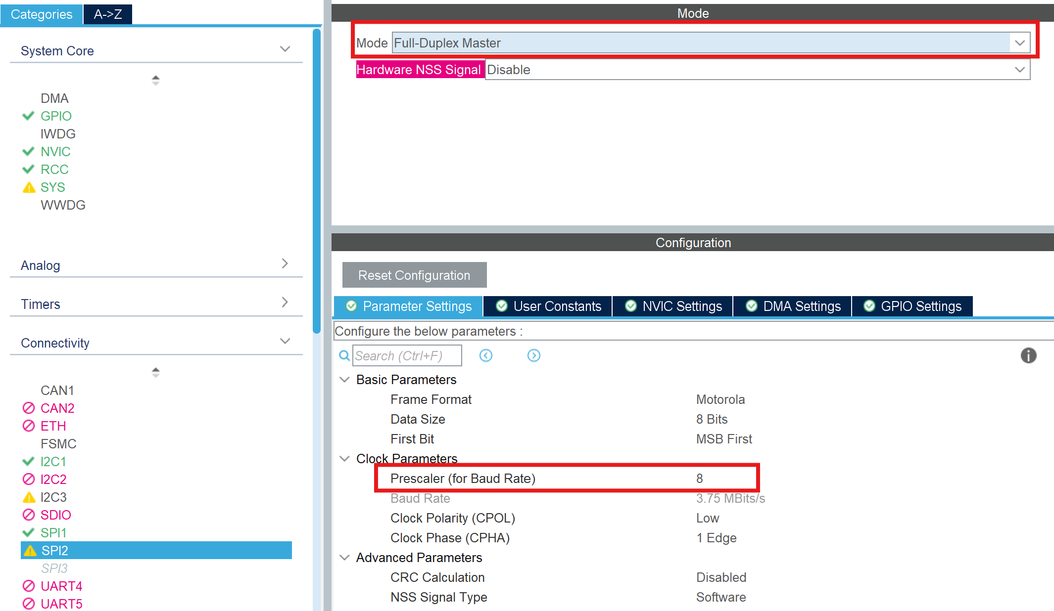
1.1 SPI 配置
-
启用 SPI2 作为 Flash 通信接口
- 模式:Full-Duplex Master
- Prescaler:8(降低 SPI 时钟,提高通信稳定性)
-
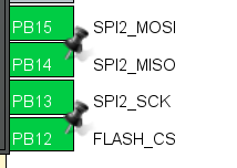
引脚配置
将 SPI2 引脚调整为同一侧排布,方便硬件连接:
-
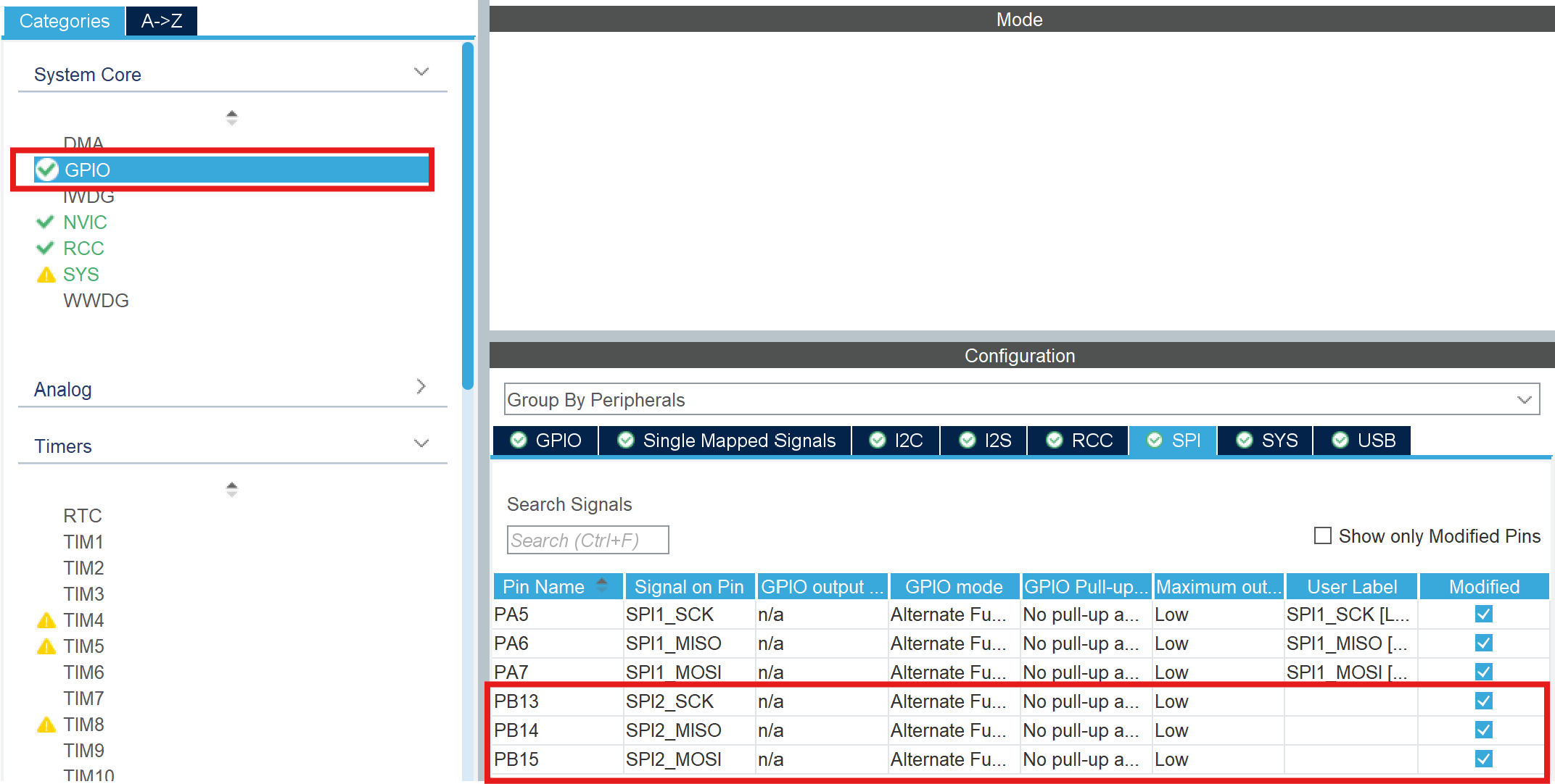
GPIO 速度配置
在 GPIO -> SPI2 中, 将 Maximum Output Speed 设置为 Low, 以降低信号频率,增强通信稳定性:
1.2 USB CDC 配置
USB_OTG-FS 选择 Device Only 模式
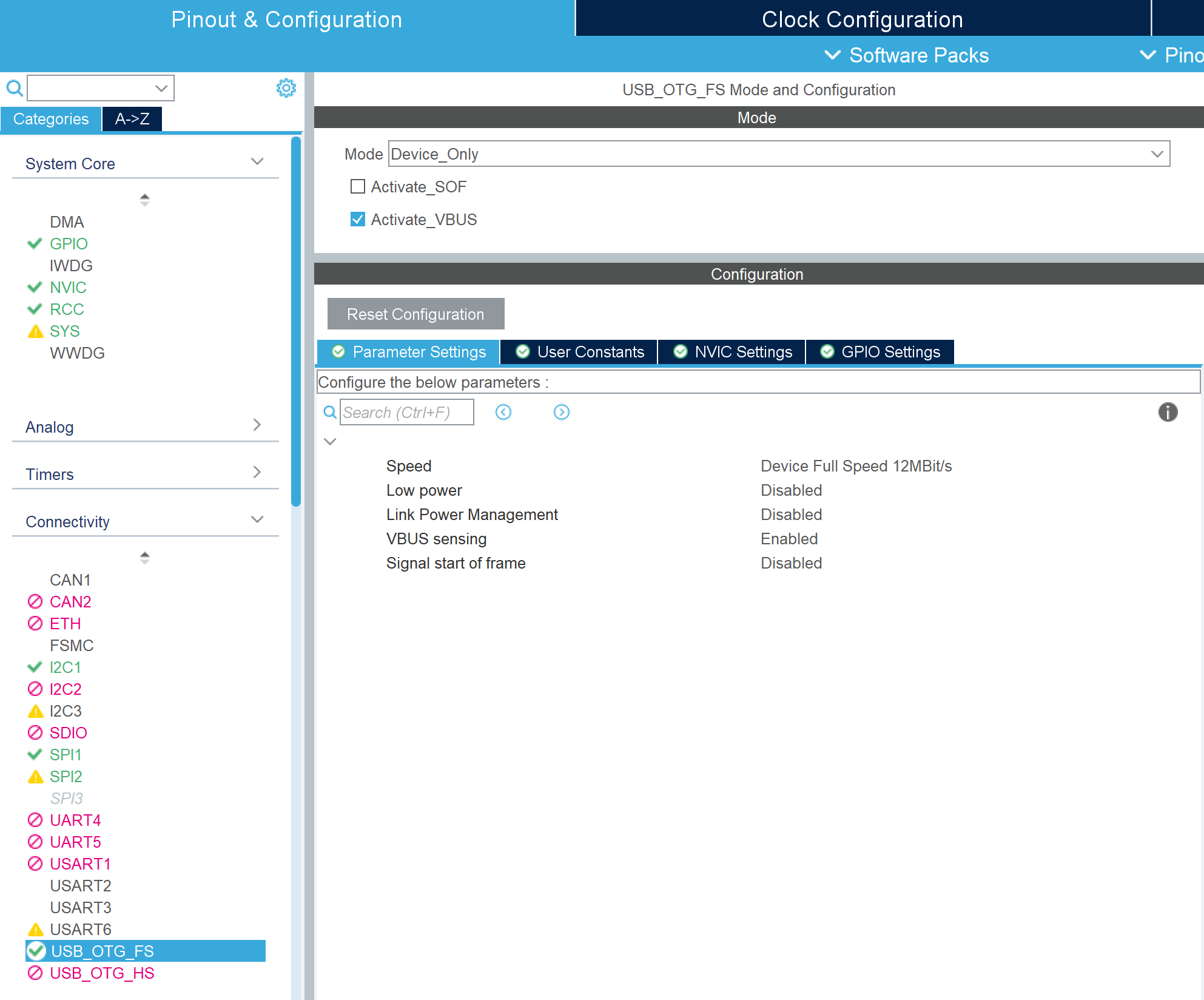
在 Middleware 中启用:
- USB Device
- Class:Communication Device Class (CDC)
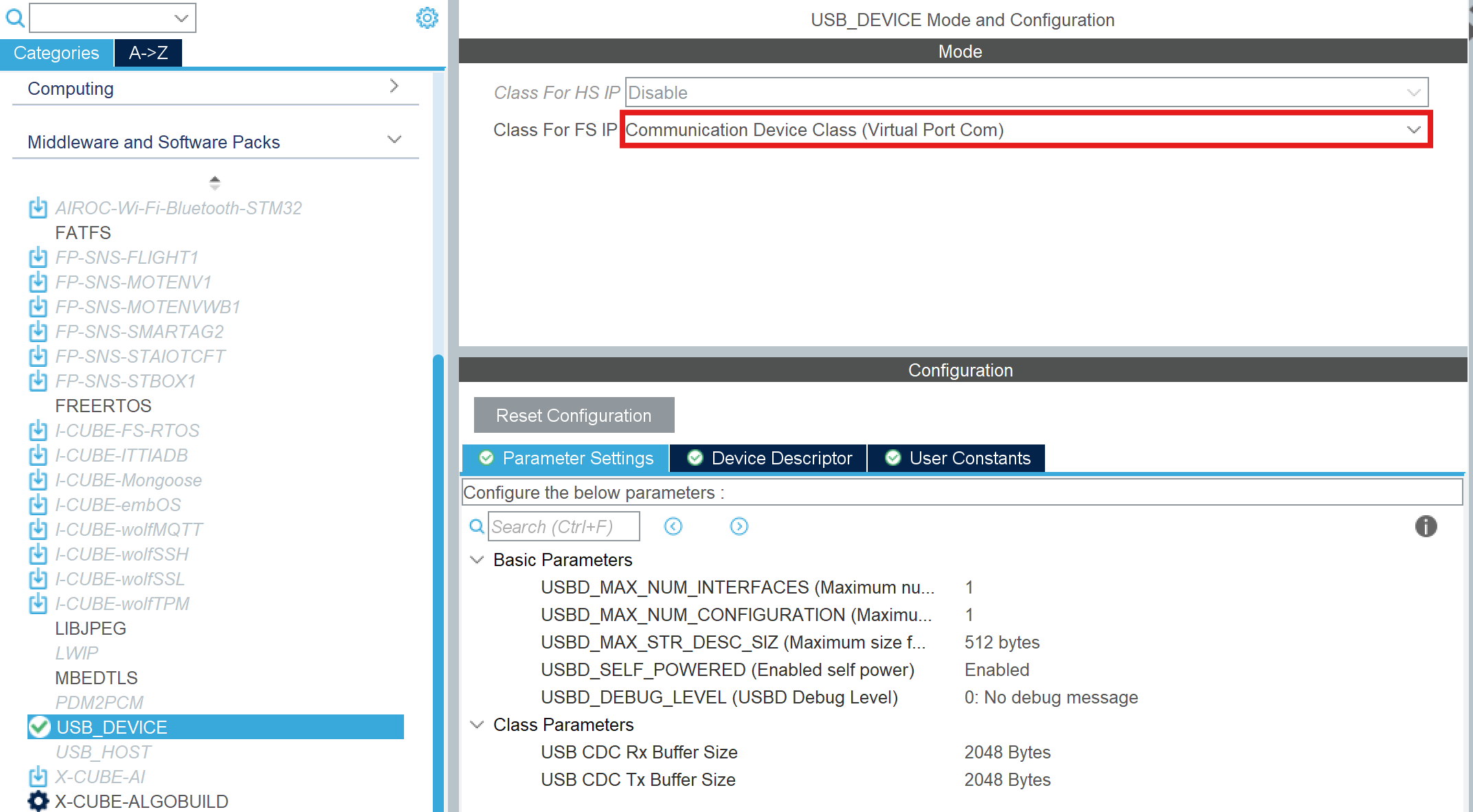
作用:
- 将开发板虚拟为串口设备
- 用于 PC ↔ MCU 数据传输(烧录固件)
2. W25Q Flash 驱动实现
cpp
// --- W25Q16 底层驱动实现 ---
#define W25Q_CS_LOW()  HAL_GPIO_WritePin(GPIOB, GPIO_PIN_12, GPIO_PIN_RESET)
#define W25Q_CS_HIGH() HAL_GPIO_WritePin(GPIOB, GPIO_PIN_12, GPIO_PIN_SET)

uint8_t SPI_RW(uint8_t byte) {
    uint8_t d_read = 0;
    HAL_SPI_TransmitReceive(&hspi2, &byte, &d_read, 1, 100);
    return d_read;
}

void W25Q_WriteEnable(void) {
    W25Q_CS_LOW();
    SPI_RW(0x06);
    W25Q_CS_HIGH();
}

void W25Q_WaitBusy(void) {
    uint8_t status = 0;
    do {
        W25Q_CS_LOW();
        SPI_RW(0x05);
        status = SPI_RW(0xFF);
        W25Q_CS_HIGH();
    } while (status & 0x01); // 只要 BUSY 位为 1 就循环
}

void W25Q_EraseChip(void) {
    W25Q_WriteEnable();
    W25Q_CS_LOW();
    SPI_RW(0xC7); // 全片擦除
    W25Q_CS_HIGH();
    W25Q_WaitBusy(); // 此处会阻塞直到擦除完成(约10秒)
}

void W25Q_WritePage(uint32_t Addr, uint8_t* pBuf, uint16_t Len) {
    W25Q_WriteEnable();
    W25Q_CS_LOW();
    SPI_RW(0x02); // 页编程
    SPI_RW((uint8_t)(Addr >> 16));
    SPI_RW((uint8_t)(Addr >> 8));
    SPI_RW((uint8_t)Addr);
    HAL_SPI_Transmit(&hspi2, pBuf, Len, 100);
    W25Q_CS_HIGH();
    W25Q_WaitBusy();
}

void W25Q_ReadBytes(uint32_t Addr, uint8_t *pBuf, uint32_t Len)
{
  /* 与 SPI_RW / Page Program 相同:逐字节全双工,避免 HAL_Transmit+Receive 与 MISO
   * 上"命令阶段即开始出数据"的时序错位,以及 DR 未按节拍读空导致的错字节 */
  W25Q_CS_LOW();
  (void)SPI_RW(0x03U);
  (void)SPI_RW((uint8_t)(Addr >> 16));
  (void)SPI_RW((uint8_t)(Addr >> 8));
  (void)SPI_RW((uint8_t)Addr);
  for (uint32_t i = 0; i < Len; i++) {
    pBuf[i] = SPI_RW(0xFFU);
  }
  W25Q_CS_HIGH();
}

void W25Q_DumpHexToCdc(uint32_t addr, uint32_t len)
{
  uint8_t row[16];
  char line[96];

  for (uint32_t off = 0; off < len; off += 16U)
  {
    uint32_t n = 16U;
    if (off + n > len) {
      n = len - off;
    }
    uint32_t a = addr + off;
    W25Q_ReadBytes(a, row, n);

    int p = snprintf(line, sizeof(line), "%08lX:", (unsigned long)a);
    if (p < 0 || (size_t)p >= sizeof(line)) {
      p = 0;
    }
    for (uint32_t i = 0; i < n; i++)
    {
      int q = snprintf(line + (size_t)p, sizeof(line) - (size_t)p, " %02X", row[i]);
      if (q < 0) {
        break;
      }
      p += q;
    }
    if ((size_t)p + 2U < sizeof(line))
    {
      line[p++] = '\r';
      line[p++] = '\n';
      line[p] = '\0';
    }
    CDC_TransmitBlocking((const uint8_t *)line, (uint16_t)p);
  }
}
3. 主循环处理逻辑
cpp
#define W25Q_HEX_DUMP_LEN  (65536u)
extern USBD_HandleTypeDef hUsbDeviceFS; // 显式声明外部 USB 句柄
uint8_t Page_Buffer[512];    // 刚好一页的缓冲区
volatile uint32_t Buf_Idx = 0;
volatile uint32_t Data_Ready = 0;
volatile uint8_t HexDump_Requested = 0;
uint32_t Current_Addr = 0;

void W25Q_WriteEnable(void);
void W25Q_WaitBusy(void);
void W25Q_EraseChip(void);
void W25Q_WritePage(uint32_t Addr, uint8_t* pBuf, uint16_t Len);
cpp
static void FlushRemainderToFlash(void)
{
  static const uint8_t ack[] = "OK\r\n";
  __disable_irq();
  uint32_t tail = Buf_Idx;
  Buf_Idx = 0;
  __enable_irq();
  if (tail > 0U) {
    W25Q_WritePage(Current_Addr, Page_Buffer, (uint16_t)tail);
    Current_Addr += tail;
  }
  (void)CDC_Transmit_FS((uint8_t *)ack, 4);
  (void)USBD_CDC_ReceivePacket(&hUsbDeviceFS);
}

static void CDC_TransmitBlocking(const uint8_t *data, uint16_t len)
{
  uint32_t t0 = HAL_GetTick();
  while (CDC_Transmit_FS((uint8_t *)data, len) == USBD_BUSY) {
    if ((HAL_GetTick() - t0) > 5000U) {
      break;
    }
  }
}
while(1)里加上:
cpp
if (Data_Ready)
{
    // 写入 256 字节到 Flash
    W25Q_WritePage(Current_Addr, Page_Buffer, 256);
    Current_Addr += 256;

    // 状态重置
    if(Buf_Idx>256)
    {
        memcpy(Page_Buffer, &Page_Buffer[256], Buf_Idx - 256);
    }
    Buf_Idx -= 256;
    Data_Ready = 0;

    // 回传 OK 信号,告知上位机发送下一包
    CDC_Transmit_FS(ack, 4);

    // 重新开启 USB 接收中断
    USBD_CDC_ReceivePacket(&hUsbDeviceFS);
}

if (HexDump_Requested)
{
    HexDump_Requested = 0;
    const char hdr[] = "\r\n--- W25Q HEX DUMP ---\r\n";
    CDC_TransmitBlocking((const uint8_t *)hdr, (uint16_t)(sizeof(hdr) - 1U));
    W25Q_DumpHexToCdc(0, W25Q_HEX_DUMP_LEN);
    const char ftr[] = "--- END ---\r\n";
    CDC_TransmitBlocking((const uint8_t *)ftr, (uint16_t)(sizeof(ftr) - 1U));
    (void)USBD_CDC_ReceivePacket(&hUsbDeviceFS);
}

/* PA0 用户键(B1):按下为高电平,松手后把缓冲区剩余数据写入 Flash */
if (HAL_GPIO_ReadPin(B1_GPIO_Port, B1_Pin) == GPIO_PIN_SET)
{
    HAL_Delay(40);

    if (HAL_GPIO_ReadPin(B1_GPIO_Port, B1_Pin) == GPIO_PIN_SET)
    {
        while (HAL_GPIO_ReadPin(B1_GPIO_Port, B1_Pin) == GPIO_PIN_SET)
        {
            HAL_Delay(2);
        }

        if (Data_Ready == 0U && Buf_Idx > 0U)
        {
            FlushRemainderToFlash();
        }
    }
}
4. USB CDC 接收回调
cpp
extern void W25Q_EraseChip(void);
extern uint8_t CDC_Transmit_FS(uint8_t* Buf, uint16_t Len);
cpp
static int8_t CDC_Receive_FS(uint8_t* Buf, uint32_t *Len)
{
  /* USER CODE BEGIN 6 */
	static uint16_t debug_buf_idx_array[1024];
	static int	array_idx = 0;
	  extern uint8_t Page_Buffer[];
	  extern volatile uint32_t Buf_Idx;
	  extern volatile uint32_t Data_Ready;

#if ENABLE_HEXDUMP
	  /* 单字节 'H':请求通过 USB 以十六进制转储 Flash(在 main 中执行,避免阻塞 USB) */
	  if (*Len == 1U && Buf[0] == (uint8_t)'H') {
	      HexDump_Requested = 1U;
	      USBD_CDC_ReceivePacket(&hUsbDeviceFS);
	      return (USBD_OK);
	  }
#endif

#if ENABLE_ERASE
	  // 如果收到 'E',执行全片擦除(用于手动触发)
	  if (Buf[0] == 'E' && *Len == 1) {
	      W25Q_EraseChip();
	      uint8_t msg[] = "Erased\r\n";
	      CDC_Transmit_FS(msg, 8);
	      USBD_CDC_ReceivePacket(&hUsbDeviceFS);
	      return (USBD_OK);
	  }
#endif

	  // 累加数据到页缓冲区
	  memcpy(&Page_Buffer[Buf_Idx], Buf, *Len);
	  Buf_Idx += *Len;

	  // 凑满一页(256字节)交给 main 处理
	  if (Buf_Idx >= 256) {
	      Data_Ready = 1;
	      debug_buf_idx_array[array_idx % 1024] = Buf_Idx;
	      array_idx ++;
	      // 注意:这里暂时不调用 ReceivePacket,等 main 写完再开
	  } else {
	      USBD_CDC_ReceivePacket(&hUsbDeviceFS);
	  }
	  return (USBD_OK);
  /* USER CODE END 6 */
}
5. 烧录固件
运行程序后,按下述步骤在 PC 端发送固件:
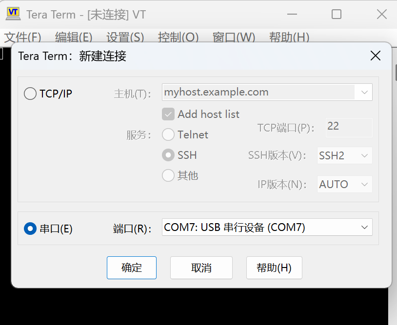
-
在串口终端(如 Tera Term)中选择名为"USB CDC"的虚拟串口并打开连接:
-
在终端菜单选择
文件 → 发送文件,选择要烧录的二进制文件并开始发送: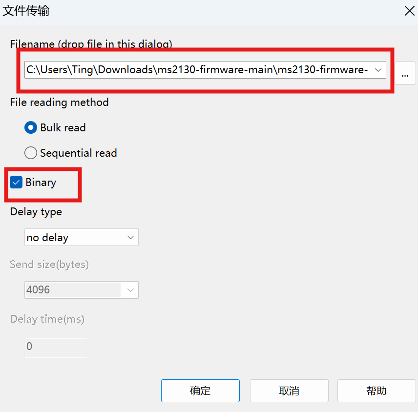
-
文件发送完成后,在开发板上按下用户键
B1,将缓冲区中剩余的数据写入 Flash: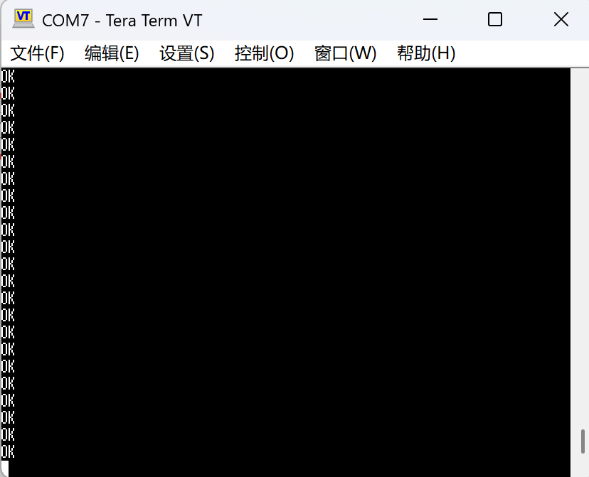
6. 验证烧录结果
烧录完成后,定义宏 ENABLE_HEXDUMP 可启用十六进制转储功能:在串口发送单字节 'H' 将请求转储 Flash 内容以便验证。转储长度由 W25Q_HEX_DUMP_LEN 控制,可按需调整。