RTT_SMART 启动过程
启动代码在cortex-a/start_gcc.S
C文件经过预处理,编译,汇编和链接才能变成可执行文件,所以学习启动过程的第一步就是看链接文件,在这里也正好复习复习cortexM下的启动相关的文件
链接文件:link_smart.lds
从链接脚本来看,链接起始地址是0xc0010000,这个值我们可以在menuconfig里面配置。那么问题来了 链接起始地址是0xc0010000 我们加载进内存可不一定是这个地址,那怎么就能实现实际物理地址和链接脚本中地址的转换了呢?暂且按下不表。
c
OUTPUT_FORMAT("elf32-littlearm", "elf32-littlearm", "elf32-littlearm")
OUTPUT_ARCH(arm)
SECTIONS
{
    /*. = 0x60010000; */
    . = 0xc0010000;
    __text_start = .;
    .text :
    {
        *(.vectors)
        *(.text)
        *(.text.*)
        /*各种杂七杂八的符号表 */
    } =0
    __text_end = .;
    .ARM.exidx   :
    {
        __exidx_start = .;
        *(.ARM.exidx* .gnu.linkonce.armexidx.*)
        __exidx_end = .;
    }
    __rodata_start = .;
    .rodata   : { *(.rodata) *(.rodata.*) }
    __rodata_end = .;
    /*不重要的就忽略*/
    __data_start = .;
    .data :
    {
        *(.data)
        *(.data.*)
    }
    __data_end = .;
    . = ALIGN(4);
    __bss_start = .;
    .bss       :
    {
    *(.bss)
    *(.bss.*)
    *(COMMON)
    . = ALIGN(4);
    }
    . = ALIGN(4);
    __bss_end = .;
    /* Stabs debugging sections....  */
    _end = .;
}
实际上这个链接脚本看起来很奇怪,所有的包括.text段bss段,data段都放在了以配置的KERNEL_VADDR_START为起始地址的一整块连续的的内存中,结合代码里面的一些宏,就可以得到程序在内存中的布局如下。
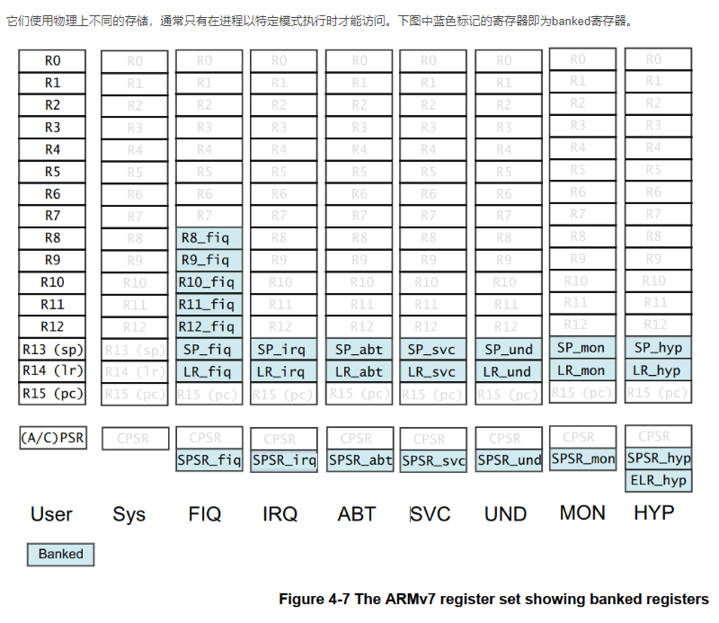
由于ARMV7架构下 每个异常模式都会有自己的SP指针,所以我们必须在内存中给每个异常模式留出对应的栈空间
c
    /*board.h里面的定义*/
    #define HEAP_BEGIN      ((void*)&__bss_end)
    #define HEAP_END        (void*)(KERNEL_VADDR_START + 16 * 1024 * 1024)
    #define PAGE_START      HEAP_END
    #define PAGE_END        (void*)(KERNEL_VADDR_START + 128 * 1024 * 1024)
    /*start.gcc下的文件 给每个异常模式提供栈空间*/
    .bss
    .align 3     /* align to  2~3=8 */
    .cpus_stack:
    svc_stack_n:
    #if defined(RT_USING_SMP) && (RT_CPUS_NR > 1)
        .space ((RT_CPUS_NR - 1) * ARM_CPU_STACK_SIZE)
    #endif
        .space (ARM_CPU_STACK_SIZE)
    svc_stack_top:
    irq_stack_n:
    #if defined(RT_USING_SMP) && (RT_CPUS_NR > 1)
        .space ((RT_CPUS_NR - 1) * ARM_CPU_STACK_SIZE)
    #endif
        .space (ARM_CPU_STACK_SIZE)
    irq_stack_top:
    und_stack_n:
    #if defined(RT_USING_SMP) && (RT_CPUS_NR > 1)
        .space ((RT_CPUS_NR - 1) * ARM_CPU_STACK_SIZE)
    #endif
        .space (ARM_CPU_STACK_SIZE)
    und_stack_top:
    abt_stack_n:
    #if defined(RT_USING_SMP) && (RT_CPUS_NR > 1)
        .space ((RT_CPUS_NR - 1) * ARM_CPU_STACK_SIZE)
    #endif
        .space (ARM_CPU_STACK_SIZE)
    abt_stack_top:
    .data
    .align 14
    init_mtbl:
        .space  (4*4096) /* The  L1 translation table therefore contains 4096 32-bit (word-sized) entries.  */

    高地址 (High Address)
    +-------------------------------------------------------+
    |  PAGE_END (若启用 SMART: +128MB)                      |
    |  ... (动态页表/堆扩展区域) ...                        |
    |  PAGE_START / HEAP_END (若启用 SMART: +16MB)          |
    |  HEAP_END (若未启用 SMART: 0x6000_0000 + 64MB)        |
    |                                                       |
    |  [ Heap Area (堆区) ]                                 |
    |  起始于:__bss_end (GCC) 或 Image$$RW_IRAM1$$ZI$$Limit|
    |  结束于:HEAP_END                                     |
    +-------------------------------------------------------+
    |  __bss_end                                            |
    |  .bss (未初始化全局/静态变量)                         |
    |  各个异常模式下的栈空间                               |
    |  *(.bss), *(COMMON)                                   |
    +-------------------------------------------------------+
    |  __data_end                                           |
    |  .init_mtbl (早期页表 16KB)                          |
    |  .data (已初始化全局/静态变量)                        |
    |  *(.data)                                             |
    +-------------------------------------------------------+
    |  __rodata_end                                         |
    |  .rodata (只读数据:const, 字符串等)                  |
    +-------------------------------------------------------+
    |  __exidx_end                                          |
    |  .ARM.exidx (ARM 异常 unwind 表)                      |
    +-------------------------------------------------------+
    |  __text_end                                           |
    |  .text (代码段)                                       |
    |   - *(.vectors) (中断向量表 )             |
    +-------------------------------------------------------+
    |  __text_start = 0xC0010000 (代码起始地址)             |
    低地址 (Low Address)
这个布局似乎和经常用的ST的M3/M4内核的布局不太一样呀,我们可以对比来看一下,在以往的布局里 对于RO和代码段 把他们放在FLASH中即可 所以在链接时地址是从0x08000000开始的 而对于bss段和data段 由于需要读写 所以它们的地址从0x20000000开始
算的 这样的话在启动的时候会对SRAM进行bss段清空和把data段搬运到SRAM中的动作。
至于为什么qemu的link_smart.lds会是这样 emmm也许因为是我们要模拟所以这么写?暂时想不明白,但是了解清楚内存布局就可以走下一步了
c
keil里面标准的链接脚本.sct
LR_IROM1 0x08000000 0x00020000  {    ; load region size_region
  ER_IROM1 0x08000000 0x00020000  {  ; load address = execution address
   *.o (RESET, +First)
   *(InRoot$$Sections)
   .ANY (+RO)
   .ANY (+XO)
  }
  RW_IRAM1 0x20000000 0x00020000  {  ; RW data
   .ANY (+RW +ZI)
  }
}
启动过程
上电后,默认只有CPU0在工作防止冲突,PC指针指向_reset,从这里跑起来
- get_pvoff:计算物理地址和链接地址的偏移
可执行文件中变量的地址都是通过链接地址+偏移量得到的,和被加载进内存的变量实际物理地址不一定相等。所以要通过get_pvoff得到真实物理地址
变量实际物理地址 = 变量链接地址 + (物理地址与链接地址偏移量)
c
/**
 * @brief   Calculate the offset between the physical address and the virtual address of the "_reset"
 *
 * @param   tmp is the register which will be used to store the virtual address of the "_reset"
 * @param   out is the register which will be used to store the pv_off (paddr - vaddr)
 */
.macro get_pvoff, tmp, out
    ldr     \tmp, =_reset   /*链接地址*/
    adr     \out, _reset    /*起始地址*/
    sub     \out, \out, \tmp
.endm
/**
 * @brief   Get the physical address of the symbol
 *
 * @param   reg is the register to store the physical address
 * @param   symbol is symbol name
 * @param   _pvoff is the offset between the physical address and the virtual address
 */
 /*利用之前计算好的"地址偏移量",把一个符号的"虚拟地址(链接地址)"修正为"物理地址(运行地址)*/
.macro get_phy, reg, symbol, _pvoff
    ldr \reg, =\symbol
    add \reg, \_pvoff
.endm 做什么-
_rest:
- 早期初始化
这里为了加速就已经启用I-Cache了,但是还没启用D-Cache,想想为什么?
cget_pvoff r0, pv_off /*pv_off是我们给r11起的别名 保存了偏移量以后要用*/ /* exit hyp mode */ bl init_cpu_mode /* clear bss section */ bl init_kernel_bss /* Initializes the assembly environment stack */ bl init_cpu_stack_early-
初始化早期页表:init_mmu_page_table_early
因为变量的链接脚本和实际在内存的物理地址有偏移,每次用的时候都得计算(QAQ),那干脆把链接地址作为虚拟地址 ,让MMU来自动算不就好啦,这样以后就能直接使用链接脚本里的地址了--rt_hw_mem_setup_early函数
不过官方想的可比我多,**可执行文件的大小可能只有1MB 可是RAM可能有1GB 这1MB和对应的物理内存是通过偏移量映射,万一需要访问除了1MB以外的内存呢?**此时虚拟地址和物理地址之间是一一映射的关系c/*pv_off 偏移量*/ if (vaddr >= KERNEL_VADDR_START && vaddr - KERNEL_VADDR_START < size) { mtbl[va] = ((va << 20) + pv_off) | NORMAL_MEM; } else if (vaddr >= (KERNEL_VADDR_START + pv_off) && vaddr - (KERNEL_VADDR_START + pv_off) < size) { mtbl[va] = (va << 20) | NORMAL_MEM; } else { mtbl[va] = 0; }初始化之后就可以enable_mmu_page_table_early了 此时D-Cache的开关打开了,但是MMU决定了内存是否可以被缓存属性 所以暂时还没用D-Cache
- 早期初始化
-
rtthread_startup:RTT的启动
此时CPU0开始启动RTT内核,而其它CPU仍处于待机状态不断执行wfe,等待CPU0唤醒它们
c
int rtthread_startup(void)
{
#ifdef RT_USING_SMP
    rt_hw_spin_lock_init(&_cpus_lock);
#endif
    rt_hw_local_irq_disable();
    /* board level initialization
     * NOTE: please initialize heap inside board initialization.
     */
    rt_hw_board_init();
    /* show RT-Thread version */
    rt_show_version();
    /* timer system initialization */
    rt_system_timer_init();
    /* scheduler system initialization */
    rt_system_scheduler_init();
#ifdef RT_USING_SIGNALS
    /* signal system initialization */
    rt_system_signal_init();
#endif /* RT_USING_SIGNALS */
    /* create init_thread */
    rt_application_init();
    /* timer thread initialization */
    rt_system_timer_thread_init();
    /* idle thread initialization */
    rt_thread_idle_init();
#ifdef RT_USING_SMP
    rt_hw_spin_lock(&_cpus_lock);
#endif /* RT_USING_SMP */
    /* start scheduler */
    rt_system_scheduler_start();
    /* never reach here */
    return 0;
}-
板级硬件初始化:rt_hw_board_init()
- 1.MMU的初始化 此时是完整的MMU页表的初始化(放在后面分析)
crt_hw_mmu_map_init(&rt_kernel_space, (void*)0x80000000, 0x10000000, MMUTable, 0); rt_hw_init_mmu_table(platform_mem_desc,platform_mem_desc_size); rt_hw_mmu_init(); rt_hw_mmu_ioremap_init(&rt_kernel_space, (void*)0x80000000, 0x10000000);- 2.内存的初始化:rt_system_heap_init()
- 3.中断控制器相关的初始化:rt_hw_interrupt_init()
- 异常向量表的初始化
- 清空全局变量isr_table
- 配置GIC中断控制器
c/* initialize vector table */ rt_hw_vector_init(); /* initialize exceptions table */ rt_memset(isr_table, 0x00, sizeof(isr_table)); /* initialize ARM GIC */ #ifdef RT_USING_SMART gic_dist_base = (uint32_t)rt_ioremap((void*)platform_get_gic_dist_base(), 0x10000); #else gic_dist_base = platform_get_gic_dist_base(); #endif gic_irq_start = GIC_IRQ_START; arm_gic_dist_init(0, gic_dist_base, gic_irq_start); arm_gic_cpu_init(0); arm_gic_redist_init(0); ``` * 4.其它注册的模块的初始化 ```c rt_components_board_init(); rt_console_set_device(RT_CONSOLE_DEVICE_NAME); rt_thread_idle_sethook(idle_wfi);- 5.安装IPI中断处理
rt_hw_ipi_handler_install(RT_SCHEDULE_IPI, rt_scheduler_ipi_handler);
IPI核间中断是处理多核之间通信的操作,Core0通过触发一个软中断强制让core1进入中断处理函数来实现同步
-
打印RTT版本:rt_show_version()
-
RTT软件定时器/调度器/空白线程/Main线程等的初始化
多核下会初始化多个空白线程(由CPU0来做 并绑定具体CPU核心 等待CPU核心拿到自己的空白线程) -
启动调度 此时进入Main线程
在Main线程中 主要做了以下事情- 1.通知其它CPU核心启动:rt_hw_secondary_cpu_up
cvoid rt_hw_secondary_cpu_up(void) { volatile void **plat_boot_reg = (volatile void **)0x10000034; char *entry = (char *)rt_secondary_cpu_entry; #ifdef RT_USING_SMART plat_boot_reg = (volatile void **)rt_ioremap_nocache((void *)plat_boot_reg, 0x1000); if (!plat_boot_reg) { /* failed */ return; } entry += PV_OFFSET; #endif *plat_boot_reg-- = (void *)(size_t)-1; *plat_boot_reg = (void *)entry; rt_hw_dsb(); rt_hw_ipi_send(0, RT_CPU_MASK ^ (1 << rt_hw_cpu_id())); }- 2.跳转Main函数执行Main函数内容
-
丛核的启动过程
- 其它CPU核心启动后做的事情:rt_hw_secondary_cpu_bsp_start()
- 初始化全局中断变量
- 初始化MMU/GIC等变量
- 将自己的tick绑定到特定定时器上(每个CPU核心都有自己的tick更新的硬件定时器)
- 启动调度(进入自己核心的IDLE线程)
cvoid rt_hw_secondary_cpu_bsp_start(void) { rt_hw_vector_init(); rt_hw_spin_lock(&_cpus_lock); rt_uint32_t mmutable_p; mmutable_p = (rt_uint32_t)MMUTable + (rt_uint32_t)PV_OFFSET ; rt_hw_mmu_switch((void*)mmutable_p) ; arm_gic_cpu_init(0, 0); /*激活中断*/ arm_gic_set_cpu(0, IRQ_PBA8_TIMER0_1, 0x2); timer_init(0, 10000); rt_hw_interrupt_install(IRQ_PBA8_TIMER0_1, rt_hw_timer2_isr, RT_NULL, "tick"); rt_hw_interrupt_umask(IRQ_PBA8_TIMER0_1); rt_system_scheduler_start(); }-
从核的tick更新
看起来CPU1-3都绑定了一个定时器,实际上cortexA9引入了"私有定时器"的概念,每个人绑定的是自己CPU核心上的私有的TIM2定时器,所以可以看到rt_tick_increase会判断是哪个CPU然后对对应的tick++cvoid rt_tick_increase(void) { RT_ASSERT(rt_interrupt_get_nest() > 0); RT_OBJECT_HOOK_CALL(rt_tick_hook, ()); /* increase the global tick */ #ifdef RT_USING_SMP /* get percpu and increase the tick */ rt_atomic_add(&(rt_cpu_self()->tick), 1); #else rt_atomic_add(&(rt_tick), 1); #endif /* RT_USING_SMP */ /* check time slice */ rt_sched_tick_increase(); /* check timer */ #ifdef RT_USING_SMP if (rt_hw_cpu_id() != 0) { return; } #endif rt_timer_check(); }
- 其它CPU核心启动后做的事情:rt_hw_secondary_cpu_bsp_start()