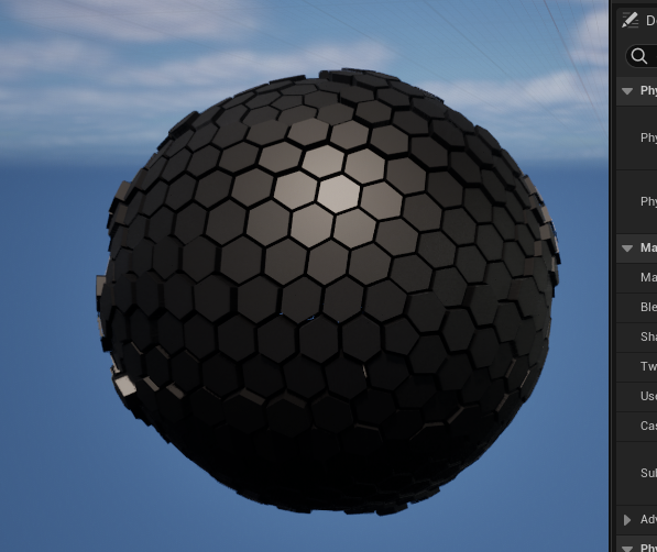
在科幻题材的视觉表现中,常出现由六边形与五边形组成的盾状结构,象征防御护甲等效果。本文将讲解如何在UE5中构建这样的球体护盾。
一.六边形/五边形 球体制作
1.因为纯六边形构建的球体在数学上不可能,因此这类球体都是由六边形与五边形组合构建。对于它的建模,你可以用DCC软件各显神通,也可以5分钟vibe coding搞定。我们用AI生成maya内的python脚本以完成该模型建模。
python
# -*- coding: utf-8 -*-
import math
from collections import defaultdict
import maya.cmds as cmds

# =========================================================
# 纯 Python 手动实现向量数学工具(零第三方库依赖)
# =========================================================

def vec_len(v):
    return math.sqrt(v[0]**2 + v[1]**2 + v[2]**2)

def normalize(v):
    length = vec_len(v)
    if length > 0:
        return [v[0] / length, v[1] / length, v[2] / length]
    return v

def vec_dot(v1, v2):
    return v1[0]*v2[0] + v1[1]*v2[1] + v1[2]*v2[2]

def vec_cross(v1, v2):
    return [
        v1[1]*v2[2] - v1[2]*v2[1],
        v1[2]*v2[0] - v1[0]*v2[2],
        v1[0]*v2[1] - v1[1]*v2[0]
    ]

def vec_sub(v1, v2):
    return [v1[0] - v2[0], v1[1] - v2[1], v1[2] - v2[2]]

def poly_center(poly):
    num_verts = len(poly)
    return [
        sum(v[0] for v in poly) / num_verts,
        sum(v[1] for v in poly) / num_verts,
        sum(v[2] for v in poly) / num_verts
    ]

# =========================================================
# 几何生成核心(二十面体对偶转换算法)
# =========================================================

def create_icosahedron(radius=1.0):
    t = (1.0 + math.sqrt(5.0)) / 2.0
    raw_verts = [
        [-1,  t,  0], [ 1,  t,  0], [-1, -t,  0], [ 1, -t,  0],
        [ 0, -1,  t], [ 0,  1,  t], [ 0, -1, -t], [ 0,  1, -t],
        [ t,  0, -1], [ t,  0,  1], [-t,  0, -1], [-t,  0,  1]
    ]
    verts = [ [component * radius for component in normalize(v)] for v in raw_verts ]
    faces = [
        [0,11,5], [0,5,1], [0,1,7], [0,7,10], [0,10,11],
        [1,5,9], [5,11,4], [11,10,2], [10,7,6], [7,1,8],
        [3,9,4], [3,4,2], [3,2,6], [3,6,8], [3,8,9],
        [4,9,5], [2,4,11], [6,2,10], [8,6,7], [9,8,1]
    ]
    return verts, faces

def subdivide(verts, faces, level=1, radius=1.0):
    for _ in range(level):
        midpoint_cache = {}
        new_faces = []

        def get_midpoint(i1, i2):
            key = tuple(sorted((i1, i2)))
            if key in midpoint_cache:
                return midpoint_cache[key]
            v1, v2 = verts[i1], verts[i2]
            vm_raw = [(v1[0] + v2[0]) * 0.5, (v1[1] + v2[1]) * 0.5, (v1[2] + v2[2]) * 0.5]
            vm = [component * radius for component in normalize(vm_raw)]
            verts.append(vm)
            idx = len(verts) - 1
            midpoint_cache[key] = idx
            return idx

        for tri in faces:
            a, b, c = tri
            ab = get_midpoint(a, b)
            bc = get_midpoint(b, c)
            ca = get_midpoint(c, a)
            new_faces.extend([[a, ab, ca], [b, bc, ab], [c, ca, bc], [ab, bc, ca]])
        faces = new_faces
    return verts, faces

def create_dual_mesh(verts, faces, radius=1.0):
    face_centers = []
    for f in faces:
        raw_center = [
            (verts[f[0]][0] + verts[f[1]][0] + verts[f[2]][0]) / 3.0,
            (verts[f[0]][1] + verts[f[1]][1] + verts[f[2]][1]) / 3.0,
            (verts[f[0]][2] + verts[f[1]][2] + verts[f[2]][2]) / 3.0
        ]
        center = [component * radius for component in normalize(raw_center)]
        face_centers.append(center)

    vertex_faces = defaultdict(list)
    for fi, face in enumerate(faces):
        for v in face:
            vertex_faces[v].append(fi)

    polygons = []
    for vi, connected_faces in vertex_faces.items():
        center = verts[vi]
        normal = normalize(center)

        tangent = [1.0, 0.0, 0.0]
        if abs(vec_dot(tangent, normal)) > 0.9:
            tangent = [0.0, 1.0, 0.0]

        tangent = normalize(vec_cross(normal, tangent))
        bitangent = normalize(vec_cross(normal, tangent))

        angles = []
        for fi in connected_faces:
            p = face_centers[fi]
            d = vec_sub(p, center)
            x = vec_dot(d, tangent)
            y = vec_dot(d, bitangent)
            angles.append((math.atan2(y, x), fi))

        angles.sort()
        polygons.append([face_centers[fi] for _, fi in angles])
    return polygons

# =========================================================
# Maya 资产生成(对调通道色彩映射版)
# =========================================================

def build_honeycomb_mesh_in_maya(mesh_name, polygons, scale=100.0):

    if cmds.objExists(mesh_name):
        cmds.delete(mesh_name)

    created_facets = []
    pentagons = 0
    hexagons = 0

    # 暂时关闭撤销队列以提高拼装效率
    cmds.undoInfo(stateWithoutFlush=False)

    try:
        for poly in polygons:
            num_verts = len(poly)
            if num_verts == 5: pentagons += 1
            elif num_verts == 6: hexagons += 1

            # 计算该单元网格的中心点与单位方向
            center = poly_center(poly)
            normal = normalize(center)

            # 1. 新的 R 通道映射:基于 XZ 平面的方位角(经度),环绕一圈是 0-1
            angle = math.atan2(normal[2], normal[0])
            r_color = (angle + math.pi) / (2.0 * math.pi)
            r_color = max(0.0, min(1.0, r_color))

            # 2. 新的 G 通道映射:基于 Y 轴高度进行归一化映射 [-1, 1] -> [0, 1]
            g_color = normal[1] * 0.5 + 0.5
            g_color = max(0.0, min(1.0, g_color))

            # 拼装单元格片面顶点的世界坐标
            pts = [(v[0] * scale, v[1] * scale, v[2] * scale) for v in poly]
            facet = cmds.polyCreateFacet(point=pts, ch=False)[0]
            created_facets.append(facet)

            # 写入对调后的颜色数据
            cmds.polyColorPerVertex(facet, rgb=(r_color, g_color, 0.0), cdo=True)

        # 1. 执行网格大融拼
        combined_mesh = cmds.polyUnite(created_facets, ch=True, name=mesh_name)[0]

        # 2. 规范化颜色集命名
        current_sets = cmds.polyColorSet(combined_mesh, q=True, allColorSets=True)
        if current_sets:
            cmds.polyColorSet(combined_mesh, edit=True, colorSet=current_sets[0], newColorSet='colorSet1')

        # 3. 固化历史
        cmds.delete(combined_mesh, ch=True)

        # 4. 视口外观设置
        cmds.polySoftEdge(combined_mesh, angle=0, ch=False) # 全硬边保持结构
        cmds.toggle(combined_mesh, vertexColor=True)        # 开启视口顶点色数据显示
        cmds.select(combined_mesh)

        print("======================================================")
        print("  Channel Swapped! Maya Honeycomb Mesh Re-generated.  ")
        print("======================================================")
        print(f"Object Name : {combined_mesh}")
        print(f"Color Set   : colorSet1 (R: Circumference, G: Vertical)")
        print(f"Total Cells : {len(polygons)}")
        print("======================================================")

    finally:
        # 恢复撤销队列设置
        cmds.undoInfo(stateWithoutFlush=True)

# =========================================================
# 执行主入口
# =========================================================
if __name__ == "__main__":
    RADIUS = 1.0
    SUBDIVISION = 3
    SCALE_FACTOR = 100.0

    MESH_NAME = "SM_ShieldSphere_Honeycomb"

    print("Executing channel-swapped geometry generation pipeline...")

    verts, faces = create_icosahedron(RADIUS)
    verts, faces = subdivide(verts, faces, level=SUBDIVISION, radius=RADIUS)
    polygons = create_dual_mesh(verts, faces, RADIUS)

    build_honeycomb_mesh_in_maya(MESH_NAME, polygons, scale=SCALE_FACTOR)
跑完之后效果长这样:
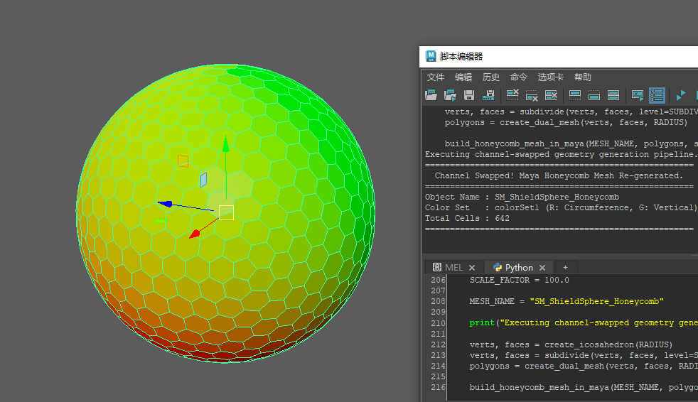
这个脚本用顶点色记录数据,每个cell是独立单元------R通道是绕周长映射的0-1区间,G通道是从下到上的映射,跟球面坐标那套逻辑一样。
2.但该球体无厚度,后序制作效果时会非常单薄,在MAYA中使用挤出命令设置厚度。
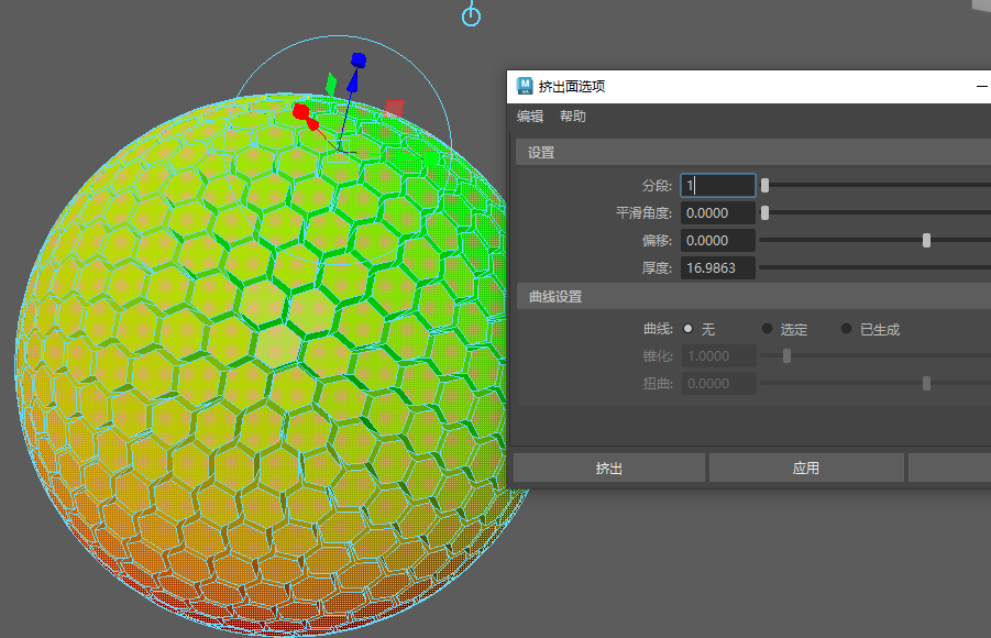
设置好后导出至到UE即可。
二.导入UE
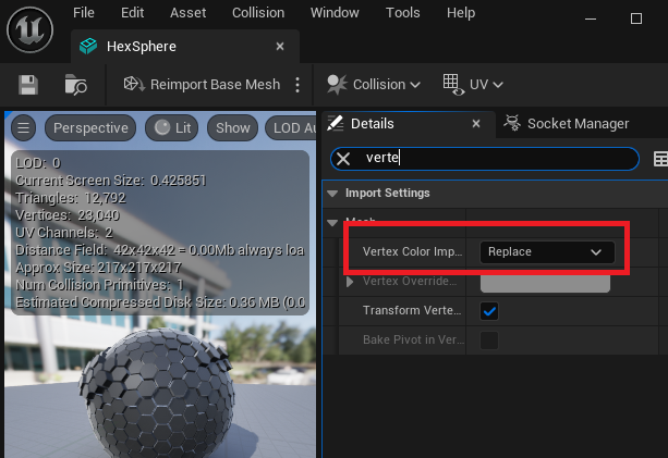
3.导入UE后检查顶点色导入是否设置,如果未设置将该选项设置为Replace,点击Reimport Base Mesh重新导入。
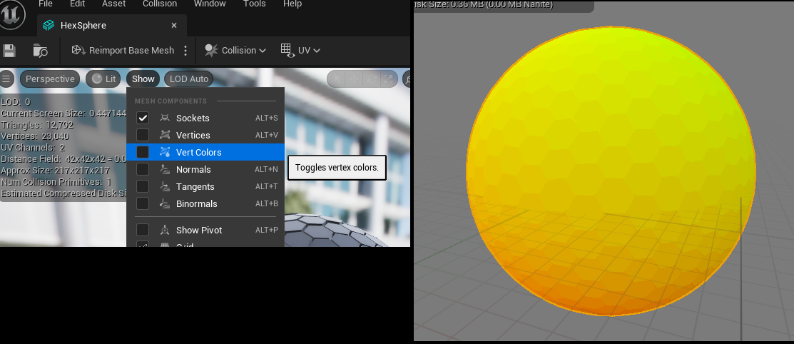
4.选择Show - Vert Color预览顶点色。
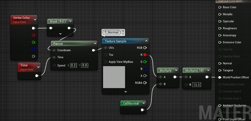
5.加几个简单节点测试下,你会发现沿着法线做正弦运动时,效果一片混乱。
6.问题是因为挤出时法线并不一致,侧面的法线与正面法线朝向不同方向导致。但即使通过法线映射为一致,光照也会出现问题。
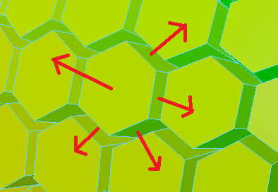
7.换个思路,之前在顶点色上缓存了球面坐标信息,可通过球面坐标反求法线。
Matrix Remap为方便使用的隐藏节点,需要通过复制粘贴命令得到:
cpp
Begin Object Class=/Script/UnrealEd.MaterialGraphNode Name="MaterialGraphNode_0"
   Begin Object Class=/Script/InterchangeImport.MaterialExpressionRemap Name="MaterialExpressionRemap_0"
   End Object
   MaterialExpression=/Script/InterchangeImport.MaterialExpressionRemap'"MaterialExpressionRemap_0"'
之所以要进行Remap值域转换,是因为UE对sin,cos进行了值域的修改,最终CellNormal为输出法线。
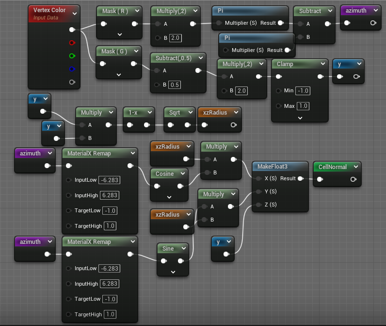
8.测试下效果。
9.最后根据你的需求继续完成制作。