【WPF】 基于 Canvas 读取并渲染 DXF 文件的技术指南
一、DXF 文件格式概述
1.1 什么是 DXF?
DXF(Drawing Exchange Format)是 AutoCAD 推出的开放矢量图形交换格式,用于在不同 CAD 软件之间传递二维和三维图形数据。对于 WPF 开发者而言,DXF 是连接传统 CAD 设计与现代桌面应用的重要桥梁。
1.2 DXF 文件结构
DXF 文件采用 ASCII 文本格式,由多个段(Section)组成,每个段包含特定的数据类型:
| 段名 | 作用 | 关键内容 |
|---|---|---|
| HEADER | 全局参数 | 图形单位、插入基点、绘图范围等 |
| CLASSES | 自定义类定义 | 应用程序自定义对象信息 |
| TABLES | 各种表格 | 图层表、线型表、文字样式表、视图表等 |
| BLOCKS | 块定义 | 可复用的图块集合 |
| ENTITIES | 实体数据 | 核心段,包含所有图形对象 |
| OBJECTS | 非图形对象 | 字典、组、布局等 |
ENTITIES 段是渲染工作的核心,包含以下常见实体类型:
-
LINE:直线段
-
CIRCLE:圆
-
ARC:圆弧
-
LWPOLYLINE / POLYLINE:多段线(轻量多段线和旧版多段线)
-
TEXT / MTEXT:单行文字和多行文字
-
ELLIPSE:椭圆
-
SPLINE:样条曲线
-
INSERT:块引用(图块插入)
-
HATCH:填充图案
二、WPF 渲染架构设计
2.1 坐标系统映射
这是 DXF 渲染中最关键的环节。DXF 使用右手坐标系,而 WPF Canvas 使用屏幕坐标系,两者存在本质差异:
| 特性 | DXF 坐标系 | WPF Canvas |
|---|---|---|
| 原点位置 | 左下角或自定义 | 左上角 |
| Y 轴方向 | 向上为正 | 向下为正 |
| 单位 | 毫米/英寸等(可配置) | 设备无关像素(DIP) |
| 坐标范围 | 可能非常大(米级) | 通常较小(像素级) |
坐标转换策略:
-
Y 轴翻转:将 DXF 的 Y 坐标取反,适应 WPF 的向下为正
-
原点平移:根据图形边界框(Bounding Box)计算偏移量,使图形居中显示
-
比例缩放:根据 Canvas 实际尺寸与图形范围的比例进行等比缩放
-
单位换算:将 DXF 的绘图单位(如毫米)转换为 WPF 的像素单位
2.2 图层与样式映射
DXF 的图层(Layer)信息需要映射到 WPF 的绘图属性:
-
颜色:DXF 使用 ACI 颜色索引(1-255),需建立索引到 Brush 的映射表
-
线型:实线、虚线、点划线等,对应 WPF 的
StrokeDashArray -
线宽:DXF 的线宽值映射到 WPF 的
StrokeThickness -
可见性:图层的开关状态控制对应 WPF 元素的
Visibility
三、核心实体渲染方案
3.1 直线(LINE)
DXF 的 LINE 实体包含起点和终点坐标 (x1, y1, z1) 和 (x2, y2, z2)。
在 WPF 中对应 Line 元素:
-
设置
X1, Y1和X2, Y2属性 -
应用坐标转换后的值
-
绑定图层样式(颜色、线宽等)
处理要点:
-
忽略 Z 坐标(纯 2D 显示时)或用于深度排序
-
考虑线型比例(LTSCALE)对虚线显示的影响
3.2 圆与圆弧(CIRCLE / ARC)
圆(CIRCLE):
-
圆心坐标
(cx, cy, cz) -
半径
r
对应 WPF 的 Ellipse 元素,但需注意:
-
Ellipse的宽度和高度为直径(2*r) -
通过
Canvas.Left和Canvas.Top定位左上角(需将圆心坐标转换为左上角坐标:left = cx - r,top = cy - r)
圆弧(ARC):
- 包含圆心、半径、起始角度和终止角度
WPF 没有原生的圆弧元素,需要使用 Path 配合 ArcSegment:
-
计算起始点和终止点坐标
-
设置
ArcSegment的Size(半径)、Point(终点)、IsLargeArc(大弧标志)、SweepDirection(扫掠方向)
3.3 多段线(LWPOLYLINE / POLYLINE)
多段线是 CAD 中最复杂的实体之一,支持:
-
直线段和圆弧段混合
-
可变宽度(起点宽度和终点宽度)
-
凸度(Bulge)定义圆弧段
渲染策略:
-
纯直线多段线:使用
Polyline元素,将顶点列表绑定到Points属性 -
含圆弧的多段线:需要分段处理:
-
遍历顶点,根据凸度值判断是直线还是圆弧
-
凸度
bulge = tan(θ/4),其中θ为圆弧圆心角 -
将圆弧段转换为多个小直线段(离散化)或使用
Path的ArcSegment
-
-
带宽度的多段线:
-
简单处理:使用
StrokeThickness模拟(但不支持渐变宽度) -
精确处理:计算每段的轮廓多边形,使用
Polygon或Path填充
-
3.4 文字(TEXT / MTEXT)
TEXT(单行文字):
-
插入点坐标
-
文字内容
-
文字高度
-
旋转角度
-
对齐方式(左对齐、居中、右对齐等)
对应 WPF 的 TextBlock:
-
设置
Text、FontSize(需根据缩放比例调整) -
使用
RenderTransform实现旋转 -
根据对齐方式计算偏移量
MTEXT(多行文字):
-
支持多行、段落格式、特殊符号
-
需要解析控制码(如
\P换行、\H高度调整等) -
在 WPF 中可使用多个
TextBlock组合或RichTextBox
字体映射问题:
-
DXF 可能使用 SHX 字体(AutoCAD 专用),WPF 不支持
-
建立字体映射表:SHX 字体 → 系统 TrueType 字体(如
txt.shx→Arial) -
处理缺失字体时的回退策略
3.5 椭圆(ELLIPSE)
DXF 的 ELLIPSE 实体使用参数方程定义:
-
中心点
-
长轴端点(定义长轴方向和长度)
-
短轴与长轴的比例
-
起始参数和终止参数(用于部分椭圆)
WPF 的 Ellipse 只能绘制正椭圆(轴对齐),对于倾斜椭圆需要使用 Path:
-
计算椭圆的几何参数
-
使用
MatrixTransform或Geometry.Transform实现旋转和缩放 -
部分椭圆需要裁剪或使用
ArcSegment近似
3.6 样条曲线(SPLINE)
DXF 支持 B 样条和 NURBS 样条曲线。
渲染方案:
-
离散化逼近:将样条曲线分割为大量小直线段
-
根据曲率自适应分割(曲率大处分割更密)
-
使用
Polyline或Path的PolyLineSegment绘制
-
-
WPF 原生支持:WPF 的
PathGeometry支持贝塞尔曲线,但 DXF 的 NURBS 需要转换为贝塞尔形式,数学处理较复杂
精度控制:
-
设置弦高误差(Chord Height Tolerance)控制离散化精度
-
平衡渲染质量与性能
3.7 填充(HATCH)
DXF 的 HATCH 实体定义填充区域:
-
边界环(外边界和内边界,即岛)
-
填充图案(实体填充、预定义图案、自定义图案)
-
图案比例和角度
WPF 渲染方案:
-
实体填充:使用
Path的Fill属性,通过FillRule处理岛(EvenOdd 或 NonZero) -
图案填充:
-
预定义图案(如 ANSI31 斜线):通过
DrawingBrush或VisualBrush实现 -
自定义图案:解析图案定义,动态生成
DrawingBrush -
注意图案的原点和角度需要随图形变换
-
-
渐变填充:DXF 的渐变填充(GRADIENT)可映射到 WPF 的
LinearGradientBrush或RadialGradientBrush
四、代码实现
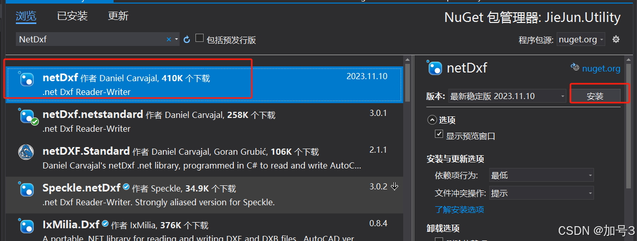
4.1 下载安装netDxf库
4.2 读取dxf文件,数据存储到DataTable
C#
using netDxf;
using netDxf.Entities;
/// <summary>
    /// 读取CAD的Dxf文件数据
    /// </summary>
    public class DxfHelperHtility
    {
        /// <summary>
        /// 读取CAD文件数据
        /// </summary>
        /// <param name="fileName"></param>
        /// <returns></returns>
        public static DataTable ReadDxf(string fileName)
        {
            DataTable dt = CreatDataTable();
            try
            {
                // 加载DXF文件
                DxfDocument dxf = DxfDocument.Load(fileName);
                netDxf.Tables.UCS ucs =dxf.DrawingVariables.CurrentUCS;
                netDxf.Collections.ImageDefinitions dd =dxf.ImageDefinitions;
                bool bRow = false;
                // 遍历所有实体
                foreach (EntityObject entity in dxf.Entities.All)
                {
                    bRow = false;
                    //添加数据行
                    DataRow drRow = dt.NewRow();
                    switch (entity)
                    {
                        case Line line:
                            //直线
                            drRow["DrawingType"] = 0;
                            drRow["StartPointX"] = ToConver(line.StartPoint.X, ucs.Origin.X);
                            drRow["StartPointY"] = ToConver(line.StartPoint.Y, ucs.Origin.Y);
                            drRow["EndPointX"] = ToConver(line.EndPoint.X, ucs.Origin.X);
                            drRow["EndPointY"] = ToConver(line.EndPoint.Y, ucs.Origin.Y);
                            drRow["Thickness"] = line.Thickness;
                            bRow = true;
                            break;
                        case Circle circle:
                            //圆形
                            drRow["DrawingType"] = 1;
                            drRow["StartPointX"] = ToConver(circle.Center.X, ucs.Origin.X);
                            drRow["StartPointY"] = ToConver(circle.Center.Y, ucs.Origin.Y);
                            drRow["Radius"] = circle.Radius;
                            drRow["Thickness"] = circle.Thickness;
                            bRow = true;
                            break;
                        case Arc arc:
                            //弧形
                            drRow["DrawingType"] = 2;
                            drRow["StartPointX"] = ToConver(arc.Center.X, ucs.Origin.X);
                            drRow["StartPointY"] = ToConver(arc.Center.Y, ucs.Origin.Y);
                            drRow["Radius"] = arc.Radius;
                            drRow["StartAngle"] = arc.StartAngle;
                            drRow["EndAngle"] = arc.EndAngle;
                            drRow["Thickness"] = arc.Thickness;
                            bRow = true;
                            break;
                        case Text text:
                            //文本
                            break;
                        case Ellipse ellipse:
                            //椭圆
                            drRow["DrawingType"] = 4;
                            drRow["StartPointX"] = ToConver(ellipse.Center.X, ucs.Origin.X);
                            drRow["StartPointY"] = ToConver(ellipse.Center.Y, ucs.Origin.Y);
                            drRow["MajorAxis"] = ellipse.MajorAxis;
                            drRow["MinorAxis"] = ellipse.MinorAxis;
                            drRow["StartAngle"] = ellipse.StartAngle;
                            drRow["EndAngle"] = ellipse.EndAngle;
                            drRow["Thickness"] = ellipse.Thickness;
                            bRow = true;
                            break;
                        case Polyline2D polyline2D:
                            drRow["DrawingType"] = 5;
                            drRow["Thickness"] = polyline2D.Thickness;
                            string data = "";
                            Polyline2DVertex startVertex = polyline2D.Vertexes[0];
                            Polyline2DVertex nextVertex;
                            double radius = 0;
                            for (int i = 0; i < polyline2D.Vertexes.Count; i++)
                            {
                                radius = 0;
                                Polyline2DVertex curVertex = polyline2D.Vertexes[i];
                                if (curVertex.Bulge != 0)
                                {
                                    //有凸度,计算半径
                                    if (i == polyline2D.Vertexes.Count)
                                    {
                                        nextVertex = startVertex;
                                    }
                                    else
                                    {
                                        nextVertex = polyline2D.Vertexes[i + 1];
                                    }
                                    radius = CalBulgeRadius(curVertex.Position.X, curVertex.Position.Y, nextVertex.Position.X, nextVertex.Position.Y, curVertex.Bulge);
                                }
                                data += string.Format("X:{0},Y:{1},Bulge:{2},StartWidth:{3},EndWidth:{4},Radius:{5}|", ToConver(curVertex.Position.X, ucs.Origin.X), ToConver(curVertex.Position.Y, ucs.Origin.Y), curVertex.Bulge, curVertex.StartWidth, curVertex.EndWidth, radius);
                            }
                            drRow["Data"] = data;
                            bRow = true;
                            break;
                        default:
                            break;
                    }

                    if (bRow)
                    {
                        dt.Rows.Add(drRow);
                    }
                }
            }
            catch (Exception ex)
            {

            }
            return dt;
        }

        /// <summary>
        /// 坐标转换
        /// </summary>
        /// <param name="value">坐标值</param>
        /// <param name="ucs">用户原点坐标</param>
        /// <returns></returns>
        private static int ToConver(double value,double ucs)
        {
            int result = 0;
            result = (int)Math.Round(value- ucs);
            return result;
        }

        /// <summary>
        /// 动态创建表格列
        /// </summary>
        /// <returns></returns>
        private static DataTable CreatDataTable()
        {
            DataTable dt = new DataTable();
            try
            {
                //添加列
                dt.Columns.Add("DrawingType", typeof(int));//类型
                dt.Columns.Add("StartPointX", typeof(double));//起点X坐标
                dt.Columns.Add("StartPointY", typeof(double));//起点Y坐标
                dt.Columns.Add("EndPointX", typeof(double));//终点X坐标
                dt.Columns.Add("EndPointY", typeof(double));//起点Y坐标
                dt.Columns.Add("Radius", typeof(double));//圆半径
                dt.Columns.Add("StartAngle", typeof(double));//起点角度
                dt.Columns.Add("EndAngle", typeof(double));//终点角度
                dt.Columns.Add("MajorAxis", typeof(double));//椭圆长轴
                dt.Columns.Add("MinorAxis", typeof(double));//椭圆短轴
                dt.Columns.Add("Thickness", typeof(double));//线宽
                dt.Columns.Add("Data", typeof(string));//线宽
            }
            catch (Exception ex)
            {

            }
            return dt;
        }
        /// <summary>
        /// 根据两点和凸度,计算半径
        /// </summary>
        /// <param name="x1"></param>
        /// <param name="y1"></param>
        /// <param name="x2"></param>
        /// <param name="y2"></param>
        /// <param name="bulge"></param>
        /// <returns></returns>
        public static double CalBulgeRadius(double x1, double y1, double x2, double y2, double bulge)
        {
            double radius = 0;
            try
            {
                if (bulge == 0)
                    return radius;
                //计算顶点角度
                double cicleAngle = Math.Atan(bulge) * 4;
                //两点之间的距离
                double pointLen = Math.Sqrt((x1 - x2) * (x1 - x2) + (y1 - y2) * (y1 - y2));
                //根据正玄值反推
                radius = (pointLen / 2) / Math.Sin(cicleAngle / 2);
                return Math.Abs(radius);
            }
            catch (Exception ex)
            {

            }
            return radius;
        }
    }
特别注意:如果用户画的图不是默认原点,而是自定义原点,需要获取用户坐标原点,其他线段点需要减去用户坐标原点才能得到正确的坐标
C#
//获取用户坐标系(UCS)的原点坐标
  netDxf.Tables.UCS ucs =dxf.DrawingVariables.CurrentUCS;
至此完成了dxf文件读取并将数据存储到DataTable,供后续处理。
4.3 DataTable数据转换成通用数据,供上层使用
C#
/// <summary>
        /// 读取CAD文件数据
        /// </summary>
        /// <param name="path"></param>
        /// <returns></returns>
        public static List<DxfModel> ReadDxf(string path)
        {
            List<DxfModel> list = new List<DxfModel>();
            DataTable dt = DxfHelperHtility.ReadDxf(path);
            if (dt == null || dt.Rows.Count <= 0)
            {
                return list;
            }
            for (int i = 0; i < dt.Rows.Count; i++)
            {
                DxfModel dxfModel = new DxfModel();
                int drawingType = Convert.ToInt16(dt.Rows[i]["DrawingType"].ToString().Trim());
                switch (drawingType)
                {
                    case 0:
                        //直线
                        dxfModel.DrawingType = drawingType;
                        dxfModel.StartPointX= Convert.ToInt16(dt.Rows[i]["StartPointX"].ToString().Trim());
                        dxfModel.StartPointY = Convert.ToInt16(dt.Rows[i]["StartPointY"].ToString().Trim());
                        dxfModel.EndPointX = Convert.ToInt16(dt.Rows[i]["EndPointX"].ToString().Trim());
                        dxfModel.EndPointY = Convert.ToInt16(dt.Rows[i]["EndPointY"].ToString().Trim());
                        dxfModel.Thickness = Convert.ToDouble(dt.Rows[i]["Thickness"].ToString().Trim());
                        list.Add(dxfModel);
                        break;
                    case 1:
                        //圆形
                        dxfModel.DrawingType = drawingType;
                        dxfModel.StartPointX = Convert.ToInt16(dt.Rows[i]["StartPointX"].ToString().Trim());
                        dxfModel.StartPointY = Convert.ToInt16(dt.Rows[i]["StartPointY"].ToString().Trim());
                        dxfModel.Radius = Convert.ToDouble(dt.Rows[i]["Radius"].ToString().Trim());
                        dxfModel.Thickness = Convert.ToDouble(dt.Rows[i]["Thickness"].ToString().Trim());
                        list.Add(dxfModel);
                        break;
                    case 2:
                        //圆弧
                        dxfModel.DrawingType = drawingType;
                        dxfModel.StartPointX = Convert.ToInt16(dt.Rows[i]["StartPointX"].ToString().Trim());
                        dxfModel.StartPointY = Convert.ToInt16(dt.Rows[i]["StartPointY"].ToString().Trim());
                        dxfModel.Radius = Convert.ToDouble(dt.Rows[i]["Radius"].ToString().Trim());
                        dxfModel.StartAngle = Convert.ToDouble(dt.Rows[i]["StartAngle"].ToString().Trim());
                        dxfModel.EndAngle = Convert.ToDouble(dt.Rows[i]["EndAngle"].ToString().Trim());
                        dxfModel.Thickness = Convert.ToDouble(dt.Rows[i]["Thickness"].ToString().Trim());
                        list.Add(dxfModel);
                        break;
                    case 3:
                        //文本
                        break;
                    case 4:
                        //椭圆
                        dxfModel.DrawingType = drawingType;
                        dxfModel.StartPointX = Convert.ToInt16(dt.Rows[i]["StartPointX"].ToString().Trim());
                        dxfModel.StartPointY = Convert.ToInt16(dt.Rows[i]["StartPointY"].ToString().Trim());
                        dxfModel.MajorAxis = Convert.ToDouble(dt.Rows[i]["MajorAxis"].ToString().Trim());
                        dxfModel.MinorAxis = Convert.ToDouble(dt.Rows[i]["MinorAxis"].ToString().Trim());
                        dxfModel.StartAngle = Convert.ToDouble(dt.Rows[i]["StartAngle"].ToString().Trim());
                        dxfModel.EndAngle = Convert.ToDouble(dt.Rows[i]["EndAngle"].ToString().Trim());
                        dxfModel.Thickness = Convert.ToDouble(dt.Rows[i]["Thickness"].ToString().Trim());
                        list.Add(dxfModel);
                        break;
                    case 5:
                        //Polyline2D
                        dxfModel.DrawingType = drawingType;
                        dxfModel.Thickness = Convert.ToDouble(dt.Rows[i]["Thickness"].ToString().Trim());
                        //解析图形坐标
                        string[] datas = dt.Rows[i]["Data"].ToString().Trim().Split('|');
                        for (int k = 0; k < datas.Count() - 1; k++)
                        {
                            Polyline polyline = new Polyline();
                            string[] messageData = datas[k].Split(',');
                            polyline.X = Convert.ToDouble(messageData[0].Split(':')[1]);
                            polyline.Y = Convert.ToDouble(messageData[1].Split(':')[1]);
                            polyline.Bulge = Convert.ToDouble(messageData[2].Split(':')[1]);
                            polyline.StartWidth = Convert.ToDouble(messageData[3].Split(':')[1]);
                            polyline.EndWidth = Convert.ToDouble(messageData[4].Split(':')[1]);
                            polyline.Radius = Convert.ToDouble(messageData[5].Split(':')[1]);
                            dxfModel.Polylines.Add(polyline);
                        }
                        list.Add(dxfModel);
                        break;
                    default:
                        break;
                }
            }
            return list;
        }

 /// <summary>
    /// CAD图形实体类
    /// </summary>
    public class DxfModel
    {
        /// <summary>
        /// 图形类型
        /// 0:直线
        /// 1:圆形
        /// 2:圆弧
        /// 3:文本
        /// 4:椭圆
        /// 5:Polyline2D
        /// </summary>
        public int DrawingType;
        /// <summary>
        /// 起点X坐标
        /// </summary>
        public double StartPointX;
        /// <summary>
        /// 起点Y坐标
        /// </summary>
        public double StartPointY;
        /// <summary>
        /// 终点X坐标
        /// </summary>
        public double EndPointX;
        /// <summary>
        /// 终点Y坐标
        /// </summary>
        public double EndPointY;
        /// <summary>
        /// 圆半径
        /// </summary>
        public double Radius;
        /// <summary>
        /// 起点角度
        /// </summary>
        public double StartAngle;
        /// <summary>
        /// 终点角度
        /// </summary>
        public double EndAngle;
        /// <summary>
        /// 椭圆长轴
        /// </summary>
        public double MajorAxis;
        /// <summary>
        /// 椭圆短轴
        /// </summary>
        public double MinorAxis;
        /// <summary>
        /// 线宽
        /// </summary>
        public double Thickness;
        /// <summary>
        /// 其他类型数据
        /// </summary>
        public string Data;
        /// <summary>
        /// Polyline数据
        /// </summary>
        public List<Polyline> Polylines = new List<Polyline>();
    }

    /// <summary>
    /// Polyline 实体
    /// </summary>
    public class Polyline
    {
        /// <summary>
        /// 坐标X
        /// </summary>
        public double X;
        /// <summary>
        /// 坐标Y
        /// </summary>
        public double Y;
        /// <summary>
        /// 凸度
        /// </summary>
        public double Bulge;
        public double StartWidth;
        public double EndWidth;
        /// <summary>
        /// 半径
        /// </summary>
        public double Radius;
    }
4.4 基于Canvas画图
Java
/// <summary>
/// 画图
/// </summary>
private void Draw()
{
try
{
if (string.IsNullOrWhiteSpace(DxfName))
{
return;
}
Path path = new Path();
PathGeometry pathGeometry = new PathGeometry();
PathFigure pathFigure = new PathFigure();
Point startPoint = new Point();
Point endPoint = new Point();
Point prePoint = startPoint;
List<DxfModel> list =FileManageBll.ReadDxf(DxfName);
foreach (var item in list)
{
switch (item.DrawingType)
{
case 0://直线
// 创建Path对象
path = new Path();
path.Stroke = System.Windows.Media.Brushes.White;
path.StrokeThickness = 1;
// 创建PathGeometry对象
pathGeometry = new PathGeometry();
// 创建PathFigure对象
pathFigure = new PathFigure();
pathFigure.StartPoint = new System.Windows.Point(item.StartPointX, -item.StartPointY);
// 创建LineSegment对象并添加到PathFigure
pathFigure.Segments.Add(new LineSegment(new System.Windows.Point(item.EndPointX, -item.EndPointY), true));
// 将PathFigure添加到PathGeometry
pathGeometry.Figures.Add(pathFigure);
// 设置Path的Data属性为PathGeometry对象
path.Data = pathGeometry;
// 将path添加到myCanvas1中
this.mainWindow.myCanvas.Children.Add(path);
break;
case 1://圆
System.Windows.Shapes.Ellipse ellipse = new System.Windows.Shapes.Ellipse
{
Width = item.Radius,
Height = item.Radius,
StrokeThickness = 1,
Stroke = System.Windows.Media.Brushes.White
};
Canvas.SetLeft(ellipse, item.StartPointX);
Canvas.SetTop(ellipse, -item.StartPointY);
this.mainWindow.myCanvas.Children.Add(ellipse);
break;
case 2: //圆弧
// 将角度转换为弧度
double startRadians = item.StartAngle * Math.PI / 180;
double endRadians = item.EndAngle * Math.PI / 180;
// 计算起点和终点的坐标(注意Y轴方向)
startPoint = new Point(
item.StartPointX + item.Radius * Math.Cos(startRadians),
-item.StartPointY - item.Radius * Math.Sin(startRadians));
endPoint = new Point(
item.StartPointX + item.Radius * Math.Cos(endRadians),
-item.StartPointY - item.Radius * Math.Sin(endRadians));
bool IsLargeArc = false;
if ((item.EndAngle - item.StartAngle + 360) % 360 >= 180)
{
//大弧
IsLargeArc = true;
}
SweepDirection direction = SweepDirection.Counterclockwise;
//if (item.StartAngle > item.EndAngle)
//{
// //逆时针
// direction = SweepDirection.Clockwise;
//}
path = new Path();
pathGeometry = new PathGeometry();
ArcSegment arc = new ArcSegment(endPoint, new Size(item.Radius, item.Radius), 0, IsLargeArc, direction, true);
PathFigure figure = new PathFigure();
figure.StartPoint = startPoint;
figure.Segments.Add(arc);
pathGeometry.Figures.Add(figure);
path.Data = pathGeometry;
path.Stroke = Brushes.White;
path.StrokeThickness = 1;
this.mainWindow.myCanvas.Children.Add(path);
break;
case 3:
break;
case 4:
break;
case 5://Polyline2D
startPoint = new Point(Convert.ToInt32(item.Polylines[0].X), -Convert.ToInt32(item.Polylines[0].Y));
double Bulge = item.Polylines[0].Bulge;
pathGeometry = new PathGeometry();
pathFigure = new PathFigure();
pathFigure.StartPoint = startPoint;
endPoint = new Point();
prePoint = startPoint;
double radius = item.Polylines[0].Radius;
PathSegment segment;
//循环各点连接成图形
for (int i = 1; i < item.Polylines.Count; i++)
{
endPoint = new Point(Convert.ToInt32(item.Polylines[i].X), -Convert.ToInt32(item.Polylines[i].Y));
segment = GetSegment(endPoint, Bulge, radius);
pathFigure.Segments.Add(segment);
radius = item.Polylines[i].Radius;
Bulge = item.Polylines[i].Bulge;
prePoint = endPoint;
}
//最后坐标连接首个坐标,完成闭合
segment = GetSegment(startPoint, Bulge, radius);
pathFigure.Segments.Add(segment);
pathGeometry.Figures.Add(pathFigure);
path = new Path
{
Stroke = Brushes.White,
StrokeThickness = 1,
Data = pathGeometry
};
this.mainWindow.myCanvas.Children.Add(path);
break;
default:
break;
}
}
}
catch (Exception ex)
{
}
}
/// <summary>
/// 获取Segment
/// </summary>
/// <param name="messageData"></param>
/// <param name="StartPoint"></param>
/// <param name="Bulge"></param>
/// <returns></returns>
private PathSegment GetSegment(Point point, double Bulge,double radius)
{
PathSegment pathSegment = null;
try
{
if (Bulge == 0)
{
pathSegment = new LineSegment(point, true);
}
else
{
bool IsLargeArc = false;
SweepDirection sweepDirection = SweepDirection.Counterclockwise;
sweepDirection = SweepDirection.Counterclockwise;
//大于1优弧
IsLargeArc = Math.Abs(Bulge) > 1;
if (Bulge < 0)
{
//小于0顺时针
sweepDirection = SweepDirection.Clockwise;
}
pathSegment = new ArcSegment(point, new Size(radius, radius), 0, IsLargeArc, sweepDirection, true);
}
}
catch (Exception ex)
{
}
return pathSegment;
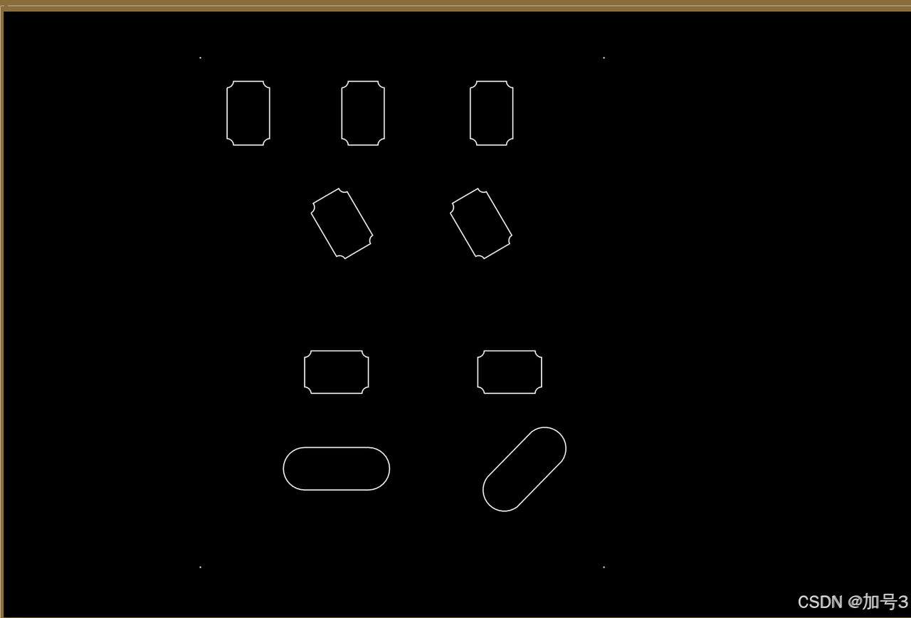
}4.5 效果图
五、典型应用场景
5.1 PCB 设计预览
结合您之前的 PCB Gerber 图形匹配项目背景,DXF 渲染可用于:
-
显示 PCB 板框、定位孔、安装孔
-
叠加显示元器件布局(与 Gerber 层对齐)
-
实现 DXF 与 Gerber 的坐标系统一和对齐
关键考虑:
-
DXF 和 Gerber 的坐标原点可能不同,需要基准点对齐
-
单位统一(DXF 通常为毫米,Gerber 可能为英寸或毫米)
-
亚像素级精度要求下,WPF 的
UseLayoutRounding和SnapToDevicePixels设置
5.2 机械图纸查看器
-
支持多布局(Model Space 和 Paper Space)
-
尺寸标注解析与显示
-
测量工具(距离、角度、面积)
5.3 CAD 数据转换中间件
-
将 DXF 转换为 WPF 的 XAML 格式
-
导出为 PNG/SVG 等图像格式
-
作为打印预览引擎
六、常见问题与解决方案
6.1 坐标显示错位
原因:DXF 的插入基点(Base Point)或 UCS(用户坐标系)变换未应用
解决:在解析时检查并应用 INSBASE 系统变量和实体级别的坐标变换矩阵
6.2 文字显示异常
原因:字体缺失、文字高度为 0、编码问题(DXF 可能使用 ANSI 或 Unicode)
解决:
-
建立全面的字体映射表
-
设置默认文字高度
-
正确处理 DXF 的组码 1(字符串值)编码
6.3 性能瓶颈
原因:实体数量过多(>10,000)、复杂样条曲线、大量填充
解决:
-
实施空间索引和视口裁剪
-
样条曲线预离散化并缓存
-
填充图案使用位图缓存
-
考虑使用
WriteableBitmap进行底层像素操作(极端性能需求)
6.4 块引用(INSERT)处理
DXF 的块引用需要递归解析:
-
读取 BLOCKS 段定义块内容
-
在 ENTITIES 段遇到 INSERT 时,实例化块并应用变换(位置、旋转、缩放)
-
处理嵌套块(块中包含块引用)
-
注意属性文字(ATTRIB)的关联显示
七、总结
在 WPF 中基于 Canvas 渲染 DXF 文件,核心挑战在于坐标系统映射、复杂实体几何转换和大规模数据性能优化。
推荐的技术路线:
-
解析层:选择成熟的 DXF 解析库(或自行实现轻量解析器),重点处理 ENTITIES 段
-
转换层:建立 DXF 实体到 WPF 元素的映射工厂,处理坐标变换和样式映射
-
渲染层:使用 Canvas 作为根容器,分层组织,实施虚拟化和缓存策略
-
交互层:封装缩放、平移、选择等操作,提供流畅的用户体验
对于需要高精度图形匹配的场景(如 PCB 制造),建议将 DXF 解析后的几何数据与图像处理管线结合,实现矢量数据与光栅数据的亚像素级配准。