【 声明:版权所有,欢迎转载,请勿用于商业用途。 联系信箱:feixiaoxing @163.com】
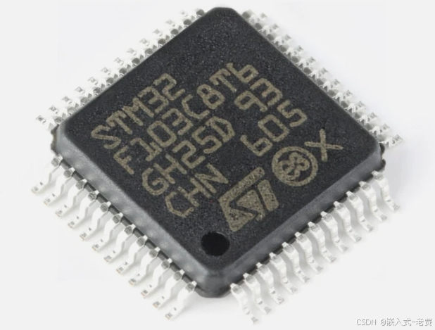
虽然esp32在消费领域用的很多,但是很多工控场合,其实stm32用的更多。就拿stm32来说,103要比407和750用得地方多很多。账面上的参数看,stm32f103性能参数一般。但是和stc89c52相比,103的性能其实已经非常够用了。
1、很多场景下103+esp32混合使用
前者一般用于控制,后者用于网络通信或者是lvgl图形显示。
2、工控领域的接口
和消费领域的spi/iic/usb/eth接口不同,工控领域更加偏向于232/485/can这些接口。特别是485和can,对于低速总线来说,几乎是最佳选择。
3、硬件准备
硬件这边的话,主要就是三样东西,即开发板、烧录器(调试器)、ttl串口。调试器的话,st-link、dap、j-link都可以,有什么用什么。
4、软件准备
软件的话,基本一个keil就够了。如果没有办法获取正版的keil,可以电商网站想想办法,或者找一点crack的工具,这也是可以的。
5、基础的电路图要看懂
做嵌入式开发,基本的接口电路图要看懂,比如说电源、gpio输出、gpio输入、ttl、232、485、can、i2c,这些基本接口需要看懂。
6、从基本的流水灯开始
一般我们学习代码都是从hello world开始,而电路板的话,则是从流水灯开始。有了流水灯,就可以以此为出发点,慢慢把其他的一些接口加进来。
#include "stm32f10x.h"                  // Device header

static void Delay_us(uint32_t xus)
{
    SysTick->LOAD = 72 * xus;               // Set timer reload value, default is 72M
    SysTick->VAL = 0x00;                    // Clear current count value
    SysTick->CTRL = 0x00000005;             // Set clock source to HCLK, start timer
    while(!(SysTick->CTRL & 0x00010000));   // Wait until count reaches zero
    SysTick->CTRL = 0x00000004;             // Disable timer
}

static void Delay_ms(uint32_t xms)
{
	while(xms--)
	{
		Delay_us(1000);
	}
}

int main(void)
{
	RCC_APB2PeriphClockCmd(RCC_APB2Periph_GPIOB, ENABLE);

	GPIO_InitTypeDef GPIO_InitStructure;  // set port attribute
	GPIO_InitStructure.GPIO_Mode = GPIO_Mode_Out_PP;
	GPIO_InitStructure.GPIO_Pin = GPIO_Pin_12;
	GPIO_InitStructure.GPIO_Speed = GPIO_Speed_50MHz;
	GPIO_Init(GPIOB, &GPIO_InitStructure);

	GPIO_InitStructure.GPIO_Mode = GPIO_Mode_Out_PP;
	GPIO_InitStructure.GPIO_Pin = GPIO_Pin_13;
	GPIO_InitStructure.GPIO_Speed = GPIO_Speed_50MHz;
	GPIO_Init(GPIOB, &GPIO_InitStructure);

	GPIO_InitStructure.GPIO_Mode = GPIO_Mode_Out_PP;
	GPIO_InitStructure.GPIO_Pin = GPIO_Pin_14;
	GPIO_InitStructure.GPIO_Speed = GPIO_Speed_50MHz;
	GPIO_Init(GPIOB, &GPIO_InitStructure);

	while (1)
	{
		GPIO_SetBits(GPIOB, GPIO_Pin_14); // turn off led here
		Delay_ms(200);
		GPIO_SetBits(GPIOB, GPIO_Pin_13);
		Delay_ms(200);
		GPIO_SetBits(GPIOB, GPIO_Pin_12);
		Delay_ms(200);

		GPIO_ResetBits(GPIOB, GPIO_Pin_14); // turn on led here
		Delay_ms(200);
		GPIO_ResetBits(GPIOB, GPIO_Pin_13);
		Delay_ms(200);
		GPIO_ResetBits(GPIOB, GPIO_Pin_12);
		Delay_ms(200);
	}
}
注1:
led ok了,下面就可以添加按键,本质上和gpio output是一回事。
#include "stm32f10x.h"                  // Device header

static void Delay_us(uint32_t xus)
{
    SysTick->LOAD = 72 * xus;               // Set timer reload value, default is 72M
    SysTick->VAL = 0x00;                    // Clear current count value
    SysTick->CTRL = 0x00000005;             // Set clock source to HCLK, start timer
    while(!(SysTick->CTRL & 0x00010000));   // Wait until count reaches zero
    SysTick->CTRL = 0x00000004;             // Disable timer
}

static void Delay_ms(uint32_t xms)
{
	while(xms--)
	{
		Delay_us(1000);
	}
}

int main(void)
{
	RCC_APB2PeriphClockCmd(RCC_APB2Periph_GPIOB, ENABLE);

	GPIO_InitTypeDef GPIO_InitStructure;  // set port attribute
	GPIO_InitStructure.GPIO_Mode = GPIO_Mode_Out_PP;
	GPIO_InitStructure.GPIO_Pin = GPIO_Pin_12| GPIO_Pin_13| GPIO_Pin_14;
	GPIO_InitStructure.GPIO_Speed = GPIO_Speed_50MHz;
	GPIO_Init(GPIOB, &GPIO_InitStructure);

	GPIO_InitStructure.GPIO_Mode = GPIO_Mode_IPU;
	GPIO_InitStructure.GPIO_Pin = GPIO_Pin_4 | GPIO_Pin_5;
	GPIO_Init(GPIOB, &GPIO_InitStructure);

	while (1)
	{
		if (GPIO_ReadInputDataBit(GPIOB, GPIO_Pin_4) == 0) // key2
		{
			GPIO_ResetBits(GPIOB, GPIO_Pin_12);
			GPIO_ResetBits(GPIOB, GPIO_Pin_13);
			GPIO_ResetBits(GPIOB, GPIO_Pin_14);
		}
		else if (GPIO_ReadInputDataBit(GPIOB, GPIO_Pin_5) == 0) // key1
		{
			GPIO_SetBits(GPIOB, GPIO_Pin_12);
			GPIO_SetBits(GPIOB, GPIO_Pin_13);
			GPIO_SetBits(GPIOB, GPIO_Pin_14);
		}
		else
		{
			GPIO_SetBits(GPIOB, GPIO_Pin_14); // turn off led here
			Delay_ms(200);
			GPIO_SetBits(GPIOB, GPIO_Pin_13);
			Delay_ms(200);
			GPIO_SetBits(GPIOB, GPIO_Pin_12);
			Delay_ms(200);

			GPIO_ResetBits(GPIOB, GPIO_Pin_14); // turn on led here
			Delay_ms(200);
			GPIO_ResetBits(GPIOB, GPIO_Pin_13);
			Delay_ms(200);
			GPIO_ResetBits(GPIOB, GPIO_Pin_12);
			Delay_ms(200);
		}
	}
}
注2:
解决了gpio输入输出,下面就是串口。经典的串口就是pa9/pa10,这边因为板子搭载了wch的串口芯片,所以直接做成回环测试的形式即可。也就是说,板子回发任何收到的packet。
#include "stm32f10x.h"                  // Device header

void USART1_Init(void)
{
	GPIO_InitTypeDef GPIO_InitStructure;
	USART_InitTypeDef USART_InitStructure;

	// Enable clocks: GPIOA + USART1
	RCC_APB2PeriphClockCmd(RCC_APB2Periph_GPIOA | RCC_APB2Periph_USART1, ENABLE);

	// PA9 - TX, alternate function push-pull output
	GPIO_InitStructure.GPIO_Mode = GPIO_Mode_AF_PP;
	GPIO_InitStructure.GPIO_Pin = GPIO_Pin_9;
	GPIO_InitStructure.GPIO_Speed = GPIO_Speed_50MHz;
	GPIO_Init(GPIOA, &GPIO_InitStructure);

	// PA10 - RX, floating input or pull-up input
	GPIO_InitStructure.GPIO_Mode = GPIO_Mode_IPU;
	GPIO_InitStructure.GPIO_Pin = GPIO_Pin_10;
	GPIO_Init(GPIOA, &GPIO_InitStructure);

	// USART1 parameter configuration
	USART_InitStructure.USART_BaudRate = 115200;
	USART_InitStructure.USART_WordLength = USART_WordLength_8b;
	USART_InitStructure.USART_StopBits = USART_StopBits_1;
	USART_InitStructure.USART_Parity = USART_Parity_No;
	USART_InitStructure.USART_HardwareFlowControl = USART_HardwareFlowControl_None;
	USART_InitStructure.USART_Mode = USART_Mode_Tx | USART_Mode_Rx;
	USART_Init(USART1, &USART_InitStructure);

	// Enable USART1
	USART_Cmd(USART1, ENABLE);
}

void USART1_SendByte(uint8_t byte)
{
	USART_SendData(USART1, byte);
	while (USART_GetFlagStatus(USART1, USART_FLAG_TXE) == RESET); // Wait until transmission completes
}

int main(void)
{
	USART1_Init();

	while (1)
	{
		// Check if data has been received
		if (USART_GetFlagStatus(USART1, USART_FLAG_RXNE) != RESET)
		{
			uint8_t receivedByte = USART_ReceiveData(USART1); // Read the received data
			USART1_SendByte(receivedByte);                    // Send it back as-is
		}
	}
}
注3:
stm32f103c8t6有三个串口,串口1是pa9和pa10,串口2是pa2和pa3,串口3是pb10和pb11。这里就看下串口3是怎么做回环转发的,
#include "stm32f10x.h"                  // Device header

void USART3_Init(void)
{
	GPIO_InitTypeDef GPIO_InitStructure;
	USART_InitTypeDef USART_InitStructure;

	// Enable clocks: GPIOB + USART3
	RCC_APB2PeriphClockCmd(RCC_APB2Periph_GPIOB, ENABLE);
	RCC_APB1PeriphClockCmd(RCC_APB1Periph_USART3, ENABLE);

	// PB10 - TX, alternate function push-pull output
	GPIO_InitStructure.GPIO_Mode = GPIO_Mode_AF_PP;
	GPIO_InitStructure.GPIO_Pin = GPIO_Pin_10;
	GPIO_InitStructure.GPIO_Speed = GPIO_Speed_50MHz;
	GPIO_Init(GPIOB, &GPIO_InitStructure);

	// PB11 - RX, floating input or pull-up input
	GPIO_InitStructure.GPIO_Mode = GPIO_Mode_IPU;
	GPIO_InitStructure.GPIO_Pin = GPIO_Pin_11;
	GPIO_Init(GPIOB, &GPIO_InitStructure);

	// USART3 parameter configuration
	USART_InitStructure.USART_BaudRate = 115200;
	USART_InitStructure.USART_WordLength = USART_WordLength_8b;
	USART_InitStructure.USART_StopBits = USART_StopBits_1;
	USART_InitStructure.USART_Parity = USART_Parity_No;
	USART_InitStructure.USART_HardwareFlowControl = USART_HardwareFlowControl_None;
	USART_InitStructure.USART_Mode = USART_Mode_Tx | USART_Mode_Rx;
	USART_Init(USART3, &USART_InitStructure);

	// Enable USART3
	USART_Cmd(USART3, ENABLE);
}

void USART3_SendByte(uint8_t byte)
{
	USART_SendData(USART3, byte);
	while (USART_GetFlagStatus(USART3, USART_FLAG_TXE) == RESET); // Wait until transmission completes
}

int main(void)
{
	USART3_Init();

	while (1)
	{
		// Check if data has been received
		if (USART_GetFlagStatus(USART3, USART_FLAG_RXNE) != RESET)
		{
			uint8_t receivedByte = USART_ReceiveData(USART3); // Read the received data
			USART3_SendByte(receivedByte);                    // Send it back as-is
		}
	}
}
注4:
如果希望慢慢构建一个系统,可以考虑加上timer定时器中断,这样基本就是一个最小系统了。后续的电机控制等功能,都可以慢慢往上加了。
#include "stm32f10x.h"                  // Device header
#include "Delay.h"
#include "OLED.h"
#include "Timer.h"

static uint16_t Num = 0;

void Timer_Init(void)
{
	RCC_APB1PeriphClockCmd(RCC_APB1Periph_TIM2, ENABLE); // set clock
	TIM_InternalClockConfig(TIM2);

	TIM_TimeBaseInitTypeDef TIM_TimeBaseInitStructure;  // set attribute
	TIM_TimeBaseInitStructure.TIM_ClockDivision = TIM_CKD_DIV1;
	TIM_TimeBaseInitStructure.TIM_CounterMode = TIM_CounterMode_Up;
	TIM_TimeBaseInitStructure.TIM_Period = 1000 - 1;  // set timer here, by feixiaoxing
	TIM_TimeBaseInitStructure.TIM_Prescaler = 7200 - 1;
	TIM_TimeBaseInitStructure.TIM_RepetitionCounter = 0;
	TIM_TimeBaseInit(TIM2, &TIM_TimeBaseInitStructure);

	TIM_ClearFlag(TIM2, TIM_FLAG_Update);
	TIM_ITConfig(TIM2, TIM_IT_Update, ENABLE);

	NVIC_PriorityGroupConfig(NVIC_PriorityGroup_2); // set interrupt

	NVIC_InitTypeDef NVIC_InitStructure;
	NVIC_InitStructure.NVIC_IRQChannel = TIM2_IRQn;
	NVIC_InitStructure.NVIC_IRQChannelCmd = ENABLE;
	NVIC_InitStructure.NVIC_IRQChannelPreemptionPriority = 2;
	NVIC_InitStructure.NVIC_IRQChannelSubPriority = 1;
	NVIC_Init(&NVIC_InitStructure);

	TIM_Cmd(TIM2, ENABLE);
}

void Led_Init()
{
	RCC_APB2PeriphClockCmd(RCC_APB2Periph_GPIOB, ENABLE);

	GPIO_InitTypeDef GPIO_InitStructure;  // set port attribute
	GPIO_InitStructure.GPIO_Mode = GPIO_Mode_Out_PP;
	GPIO_InitStructure.GPIO_Pin = GPIO_Pin_12 |GPIO_Pin_13 |GPIO_Pin_14 ;
	GPIO_InitStructure.GPIO_Speed = GPIO_Speed_50MHz;
	GPIO_Init(GPIOB, &GPIO_InitStructure);
}

void TIM2_IRQHandler(void) // interrupt function
{
	if (TIM_GetITStatus(TIM2, TIM_IT_Update) == SET)
	{
		if(Num == 0)
		{
			GPIO_SetBits(GPIOB, GPIO_Pin_14);
			GPIO_SetBits(GPIOB, GPIO_Pin_13);
			GPIO_SetBits(GPIOB, GPIO_Pin_12);
			Num = 1;
		}
		else
		{
			GPIO_ResetBits(GPIOB, GPIO_Pin_14);
			GPIO_ResetBits(GPIOB, GPIO_Pin_13);
			GPIO_ResetBits(GPIOB, GPIO_Pin_12);
			Num = 0;
		}

		TIM_ClearITPendingBit(TIM2, TIM_IT_Update);
	}
}

int main(void) // file starts here
{
	Timer_Init();
	Led_Init();

	while (1)
	{
	}
}