本文以Altera公司生产的Cyclone IV系列的EP4CE15F17C8为主芯片的CRD500开发板作为项目的硬件实现平台,并以Quarter 18.1和ModelSim为开发工具和仿真工具。
目录
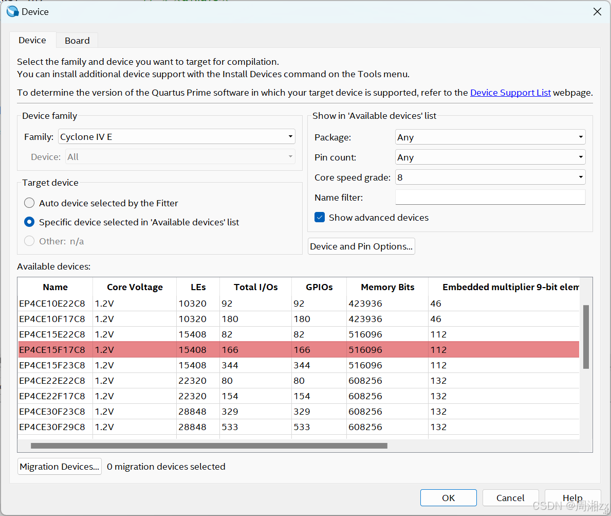
(3)选择目标芯片,选择CRD500开发板FPGA芯片EP4CE15F17C8。
[(1)方法一:基于Quartus 自身工具模块的仿真](#(1)方法一:基于Quartus 自身工具模块的仿真)
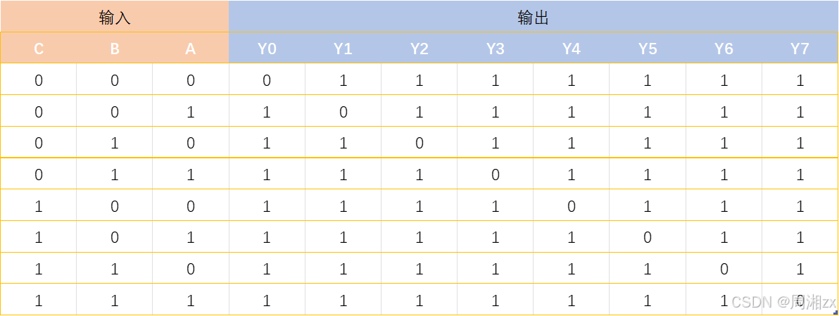
一、3-8译码器工作原理
3个输入信号进行译码,得到8个输出状态,输入与输出的关系如下表所示,表中1表示高电平,0表示低电平。
二、设计步骤
1、创建工程文件夹和编辑设计文件
(1)新建文件夹decoder_38
路径:D:\Verilog\txhFPGA\decoder_38
注:文件夹名不能包含中文
(2)输入源程序
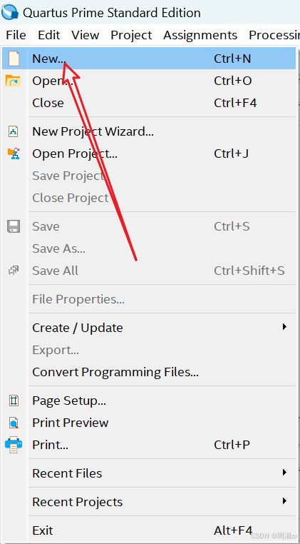
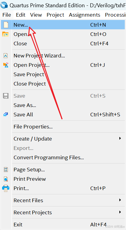
选择菜单"File" --> "New"
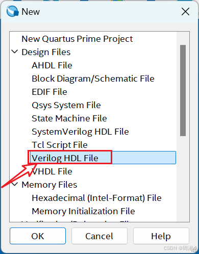
选择"Verilog HDL File"
输入程序:
javascript
//3_8译码器程序,key1,key2,key3为译码器的输入,out为译码器的输出
module decoder_38(out, key_in);
output[7:0] out; // 说明信号out的流向
input[2:0] key_in; // 说明信号key_in的流向
reg[7:0] out; // 申明信号类型
always @(key_in) // 定义always块
begin
case(key_in)
3'd0: out=8'b11111110; //key_in = 000, out[0]为低电平
3'd1: out=8'b11111101;
3'd2: out=8'b11111011;
3'd3: out=8'b11110111;
3'd4: out=8'b11101111;
3'd5: out=8'b11011111;
3'd6: out=8'b10111111;
3'd7: out=8'b01111111;
endcase
end
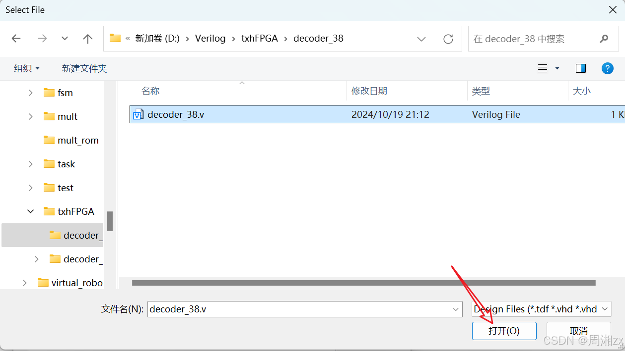
endmodule(3)文件存盘
快捷键"CTRL+S"保存文件,找到要保存的文件夹D:\Verilog\txhFPGA\decoder_38
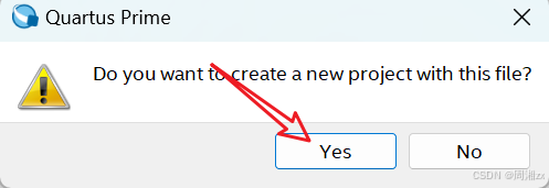
文件名应与实体名保持一致,故文件名命名为decoder_38.v。保存后弹出对话框,点击"Yes"。
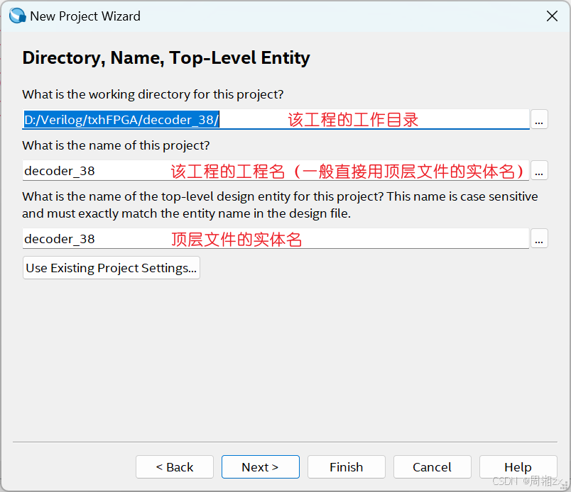
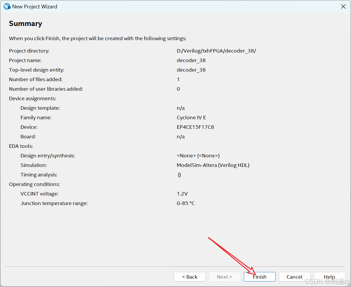
2、创建工程
(1)工程名、实体名
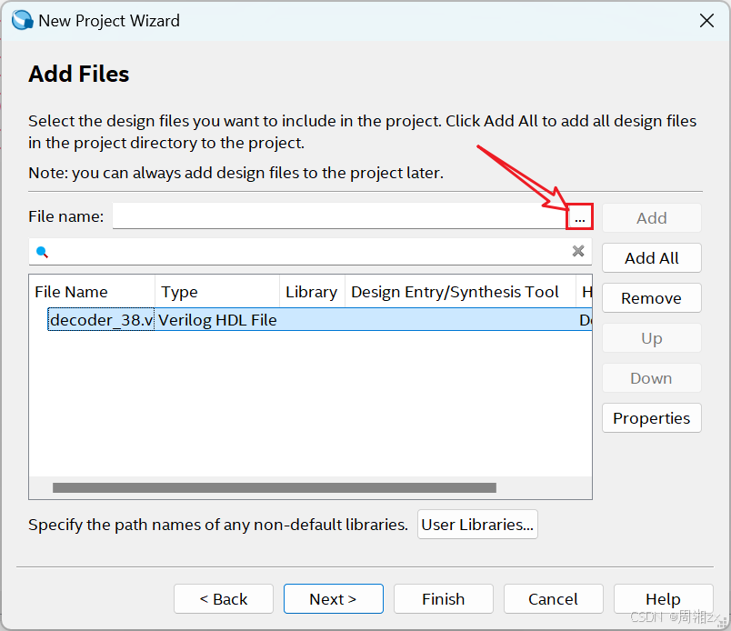
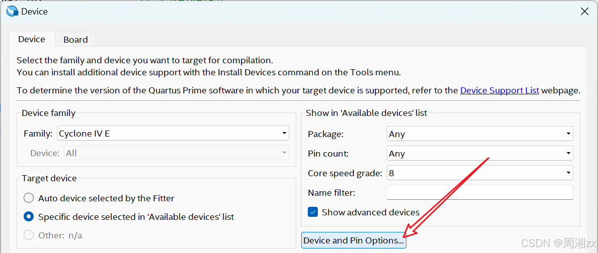
(2)将设计文件加入工程,单击下图的"···"按钮。
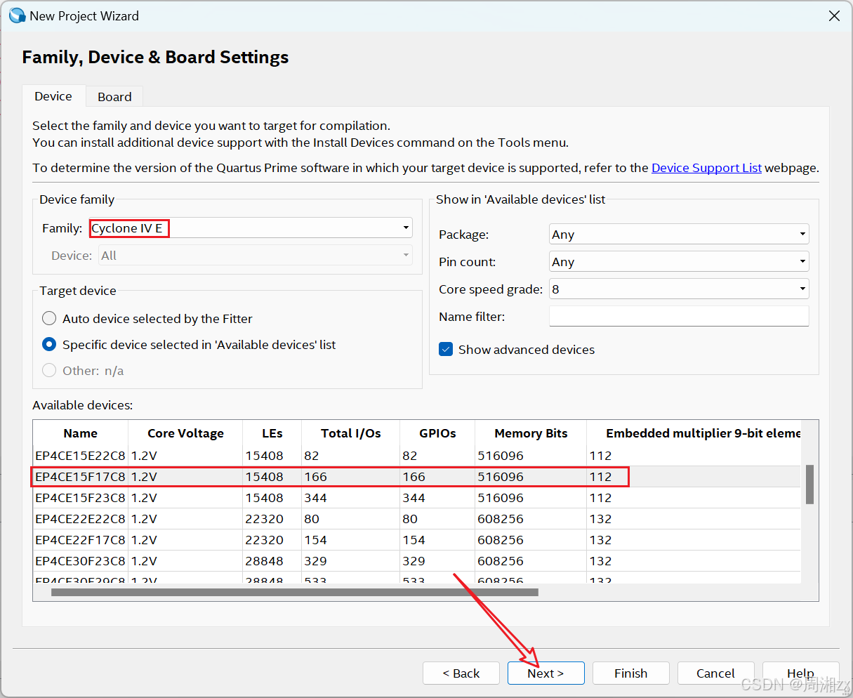
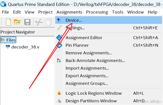
(3)选择目标芯片,选择CRD500开发板FPGA芯片EP4CE15F17C8。
(4)选择综合器和仿真器类型
若选"None",表示选择Quartus II 自带的综合器与仿真器。
对于简单设计项目,激励信号有规律,可选自带的仿真工具产生波形激励文件,作为信号源进行仿真。而对于复杂项目,激励信号无规律或很复杂,此时须选择第三方仿真软件(ModelSim_Altera)

(5)结束设置
显示本工程项目的层次结构和各层次的实体名
建立工程后,可使用"Project"菜单中的"Add/Remove Files in Project···"选项页在工程中设计、添加或删除其他文件。
或者:


3、编译工程
(1)编译前的设置
选择目标器件
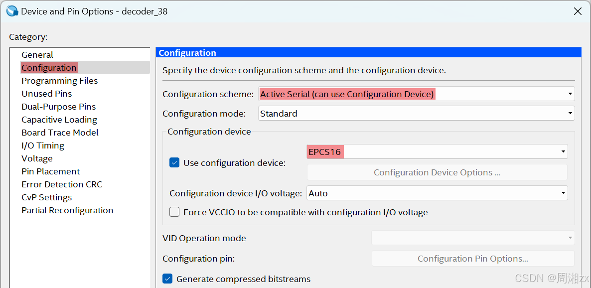
选择配置器件的编程配置方式
"Active Serial"这种方式指对专用配置器件(如项目中使用EPCS16)进行配置用的编程方式,而PC对此FPGA的直接配置方式都是JTAC方式。在"Configuration device"项目中选择配置芯片为"EPCS16"。
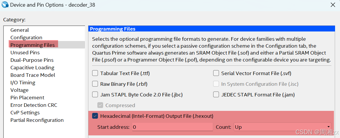
选择编译后的输出文件格式(可选)。
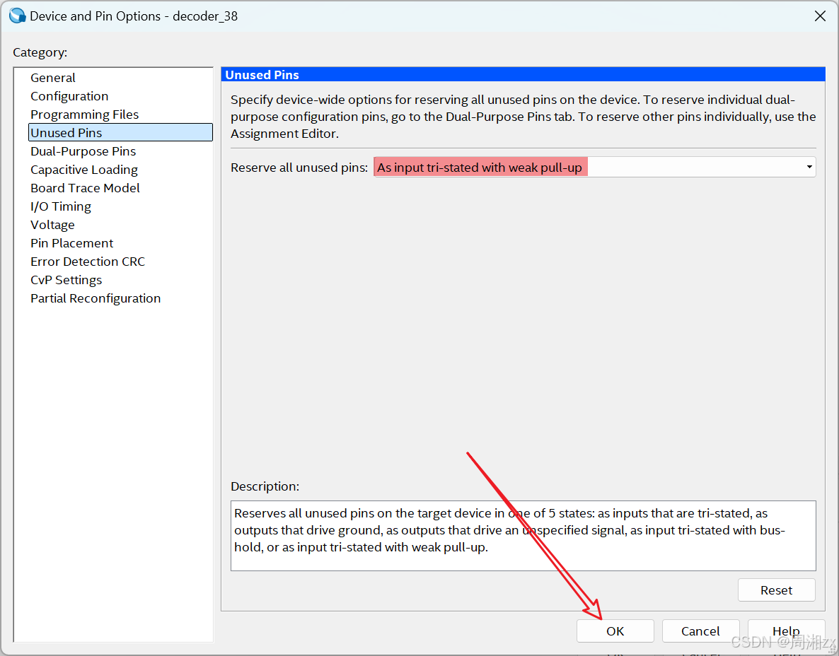
选择目标器件闲置引脚的状态(可选)
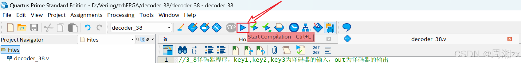
(2)编译
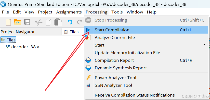
或者
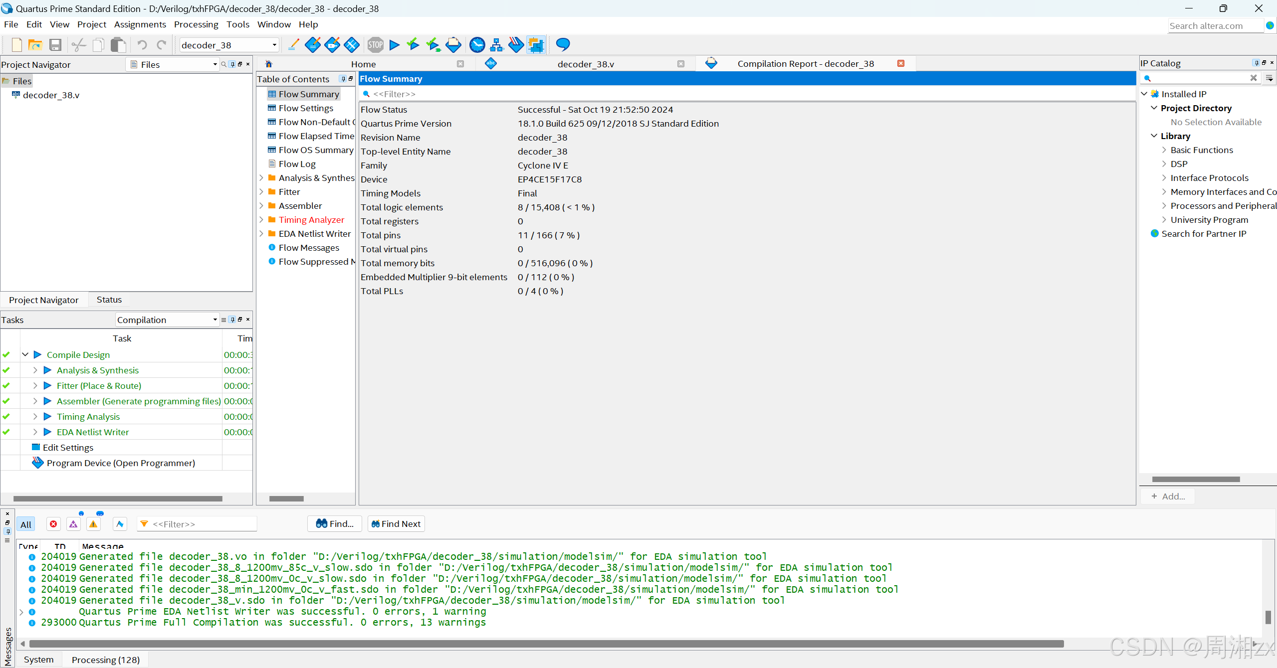
若编译成功,则:
4、仿真测试
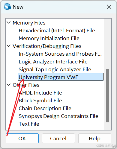
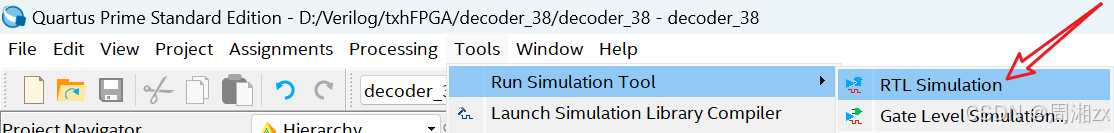
(1)方法一:基于Quartus 自身工具模块的仿真
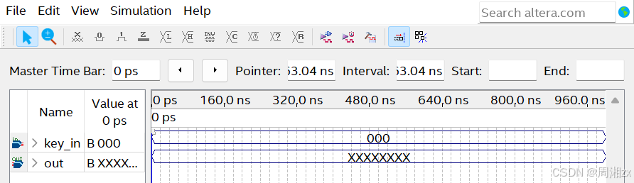
第一步:建立激励文件
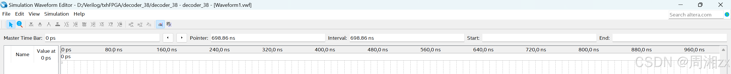
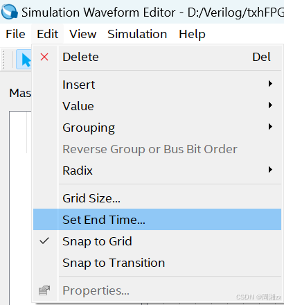
第二步:设置仿真时间区域
第三步:保存波形文件。使用"File"菜单中的"Save As"项,将decoder_38.vwf的波形文件存入工程文件夹D:\Verilog\txhFPGA\decoder_38中。
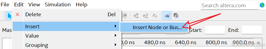
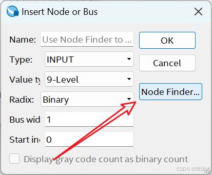
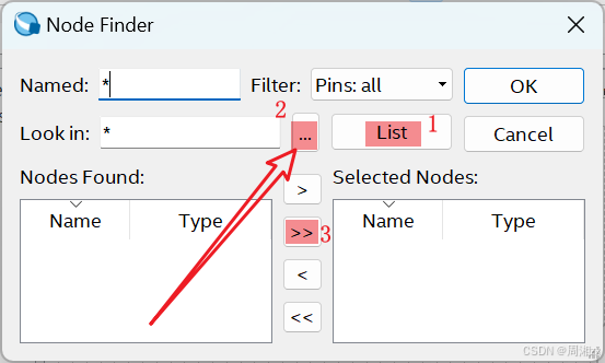
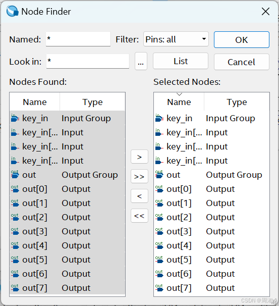
第四步:输入信号节点,将3-8译码器的端口信号选入波形编辑器中。
选择完毕后按"OK"。
第五步:编辑输入波形(输入激励信号)。
单击选中图中的key_in0,使之变成蓝色,再单击时钟,在"Clock"对话框中设置周期为20us、占空比为50%的周期信号。
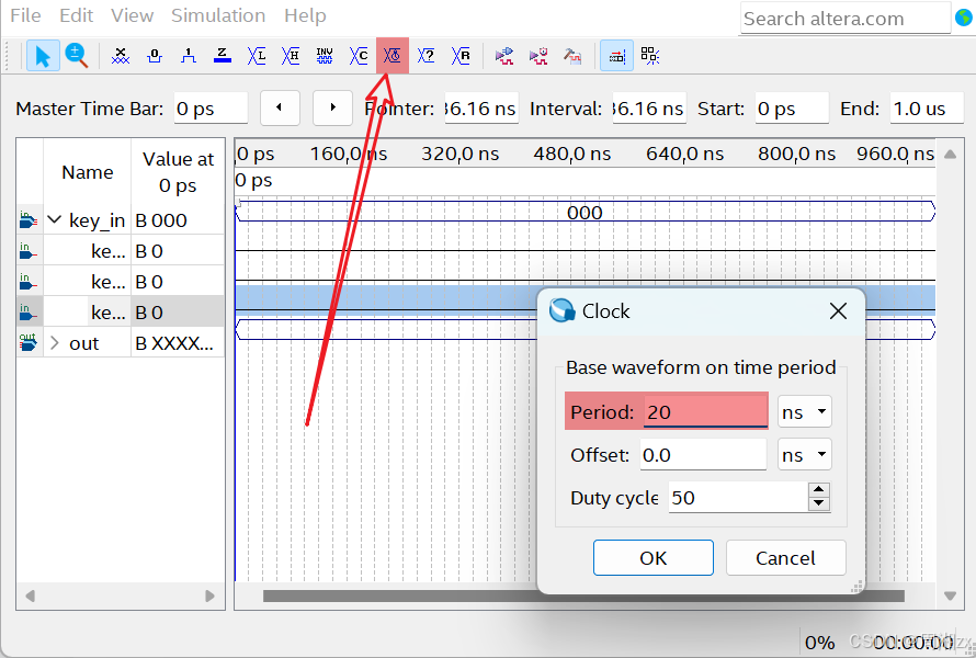
得到key_in0的波形
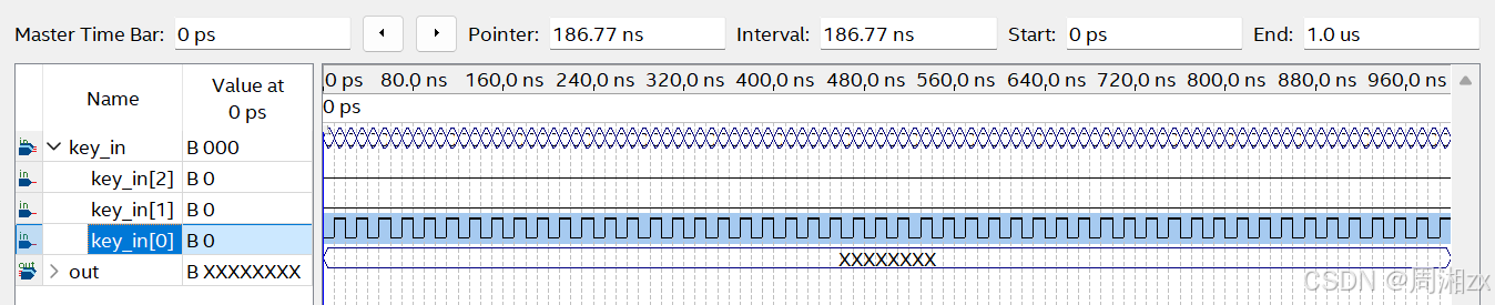
同理将key_in1设置为周期为40us、占空比为50%的周期信号;
在key_in2的波形编辑区,前30us设置为低电平,再设置30us为高电平,40us为低电平。
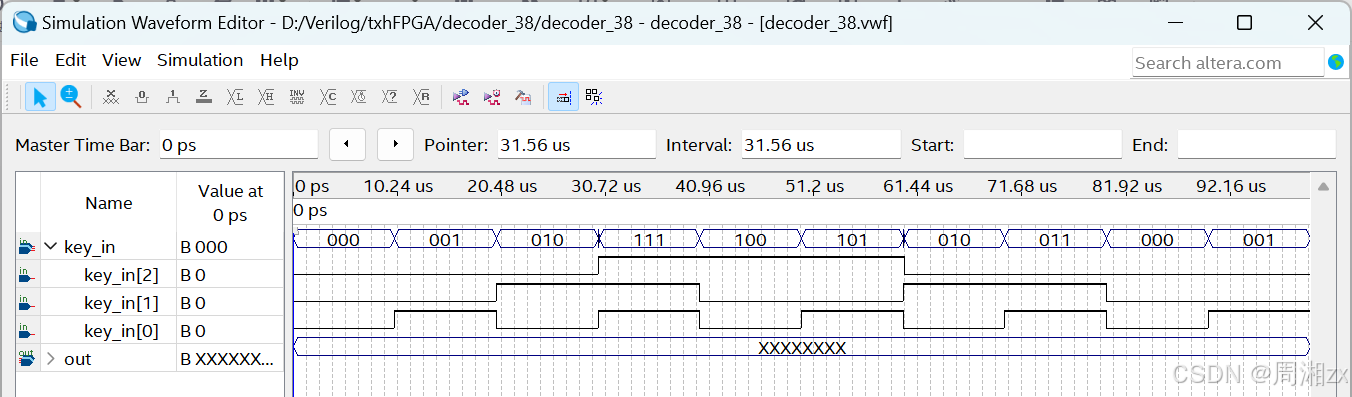
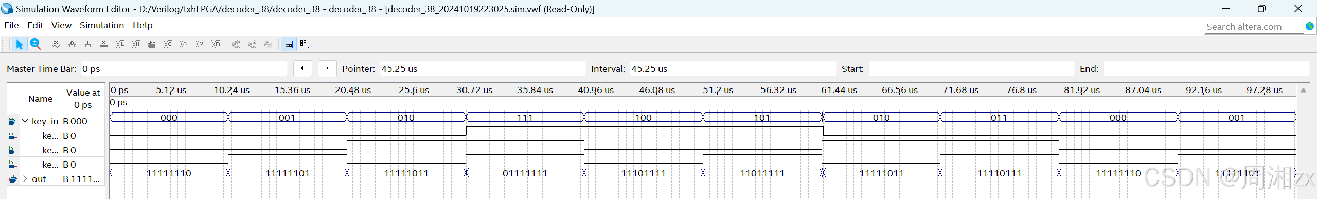
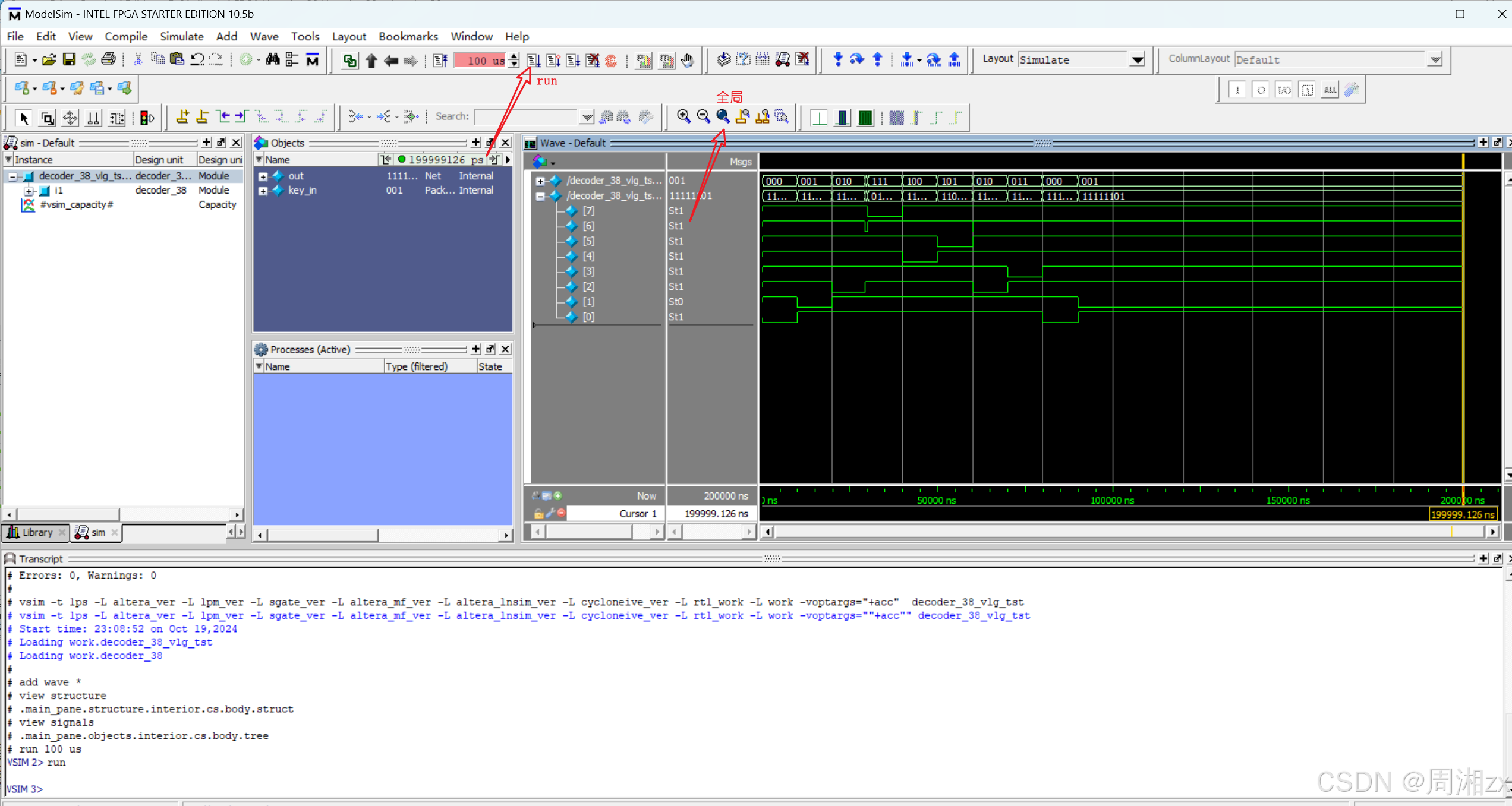
仿真测试:
(2)基于modelsim_altera的仿真
第一步:编写激励文件
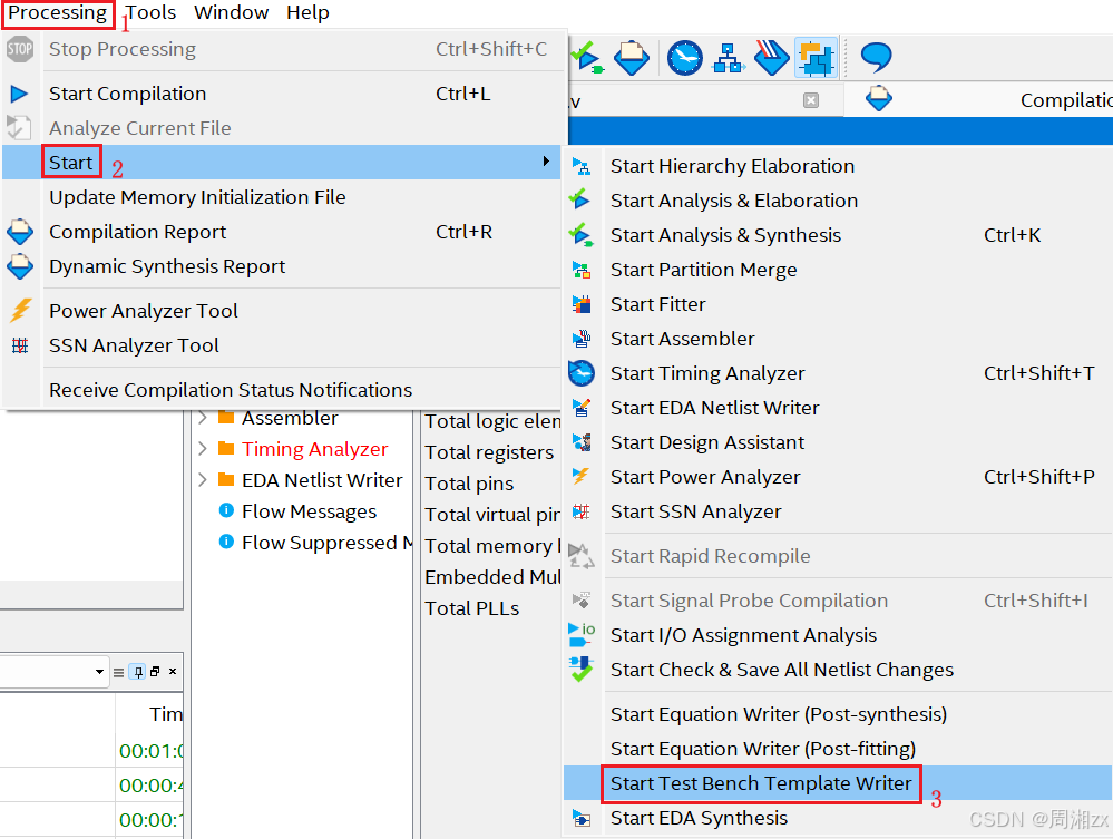
创建testbench激励文件模板。
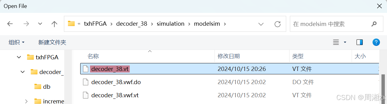
打开模板文件,修改保存,得到激励文件。选择"File"菜单中的"Open"项,打开D:\Verilog\txhFPGA\decoder_38\simulation\modelsim\decoder_38.vt文件(创建的模板默认存放位置,且文件名自动命名)
激励脚本内容:
javascript
`timescale 1 ps/ 1 ps
module decoder_38_vlg_tst();

//reg eachvec;
// test vector input registers
reg [2:0] key_in;
// wires
wire [7:0]  out;

// assign statements (if any)
decoder_38 i1 (
// port map - connection between master ports and signals/registers
	.key_in(key_in),
	.out(out)
);
initial	//key_in[2]
begin
	key_in[2] = 1'b0;
	key_in[2] = #29440000 1'b1;
	key_in[2] = #30720000 1'b0;
end

initial	//key_in[1]
begin
	repeat(2)
	begin
		key_in[1] = 1'b0;
		key_in[1] = #20000000 1'b1;
		# 20000000;
	end
	key_in[1] = 1'b0;
end

initial	//key_in[0]
begin
	repeat(5)
	begin
		key_in[0] = 1'b0;
		key_in[0] = #10000000 1'b1;
		# 10000000;
	end
end
endmodule
第二步:设置仿真环境参量
依据激励文件修改参量,将"Time scale"栏设置为"1ps"(与激励文件一致)
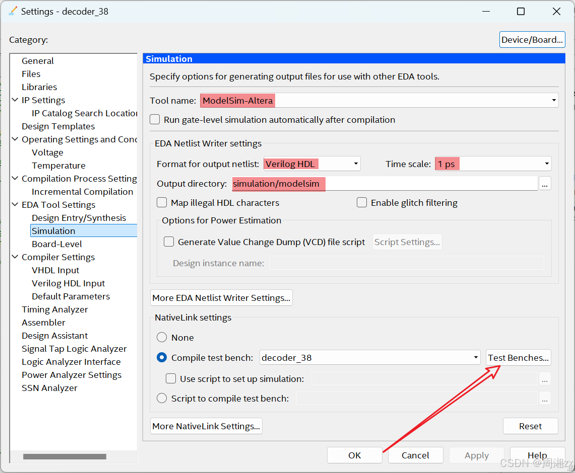
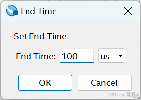
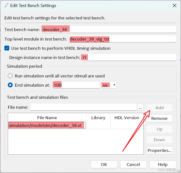
找到并添加激励文件,填写激励文件名、激励文件中的module名、激励文件中的实例名"i1",选中"End simulation at"并填写数字100,单位为"us"(与激励文件一致)。
ModelSim仿真
启动仿真,观察仿真结果(单击后跳转ModelSim,将自动获得仿真结果)
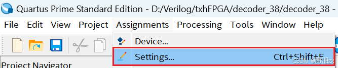
若是第一次使用Modelsim-Altera,需建立Quartus Prime和Modelsim的链接。
设置仿真文件的格式与目录


5、引脚锁定与.sof文件下载
(1)引脚锁定
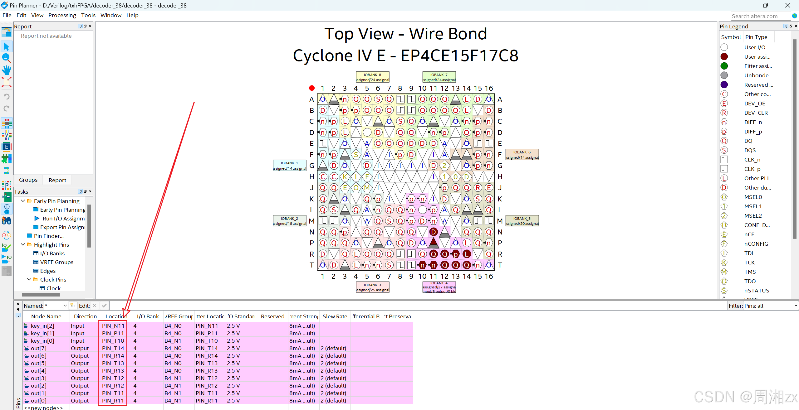
引脚锁定后,必须再编译一次,将引脚信息编译进下载文件中。在编译后产生的文件中,.sof格式的文件可直接下载到FPGA中运行。
引脚的绑定依据:
(1)FPGA与CRD500开发板上5个按键的连接关系:
|----------|---------|----------|----------|----------|----------|
| 信号名称 | rst | key1 | key2 | key3 | key4 |
| FPGA引脚 | P14 | T10 | P11 | N11 | N12 |
| 功能 | 键按下------高电平;不按------低电平 |||||
(2)8个LED灯与FPGA连接关系:
|----------|------------|------------|------------|------------|------------|------------|------------|------------|
| 信号名称 | Led(0) | Led(1) | Led(2) | Led(3) | Led(4) | Led(5) | Led(6) | Led(7) |
| FPGA引脚 | R11 | T11 | R12 | T12 | R13 | T13 | R14 | T14 |
| 功能 | 1------亮;0------灭 ||||||||
(2)选择编程模式和配置
为将编译产生的.sof文件配置进FPGA中进行测试,首先将系统连接好,开发板上电,后在"Tool"菜单中选择"Programmer"。在"Mode"栏选择编程模式为"JTAG",单击选中出现的下载文件右侧的第一个小方框,打勾。若此文件未出现,则点击左侧的"Add File",选择配置文件decoder_38.sof。

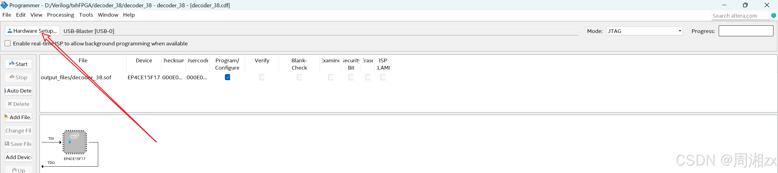
单击"Hardware Setup"后,在弹出的对话框中选择硬件,然后单击"Close"按钮。
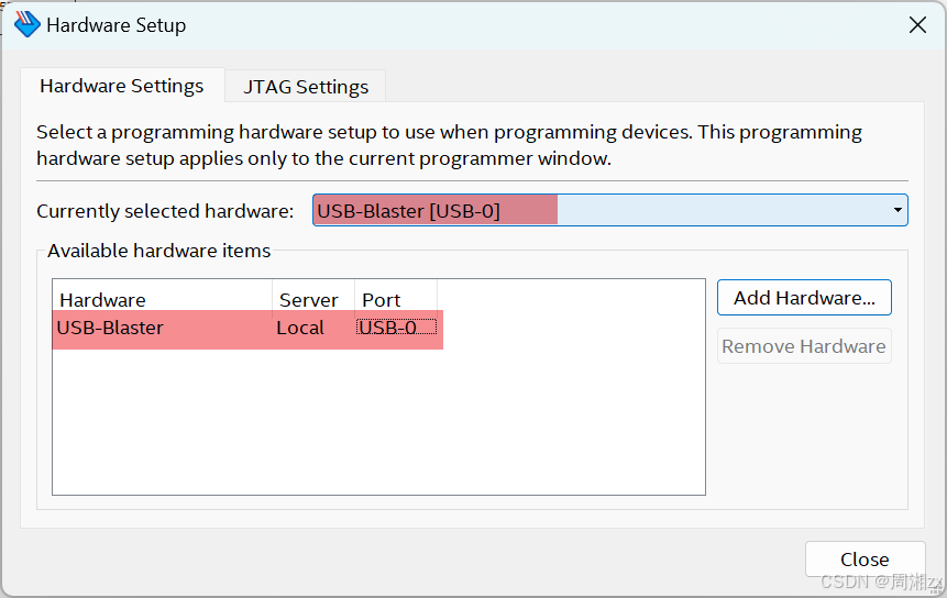
若未出现硬件,则参考:
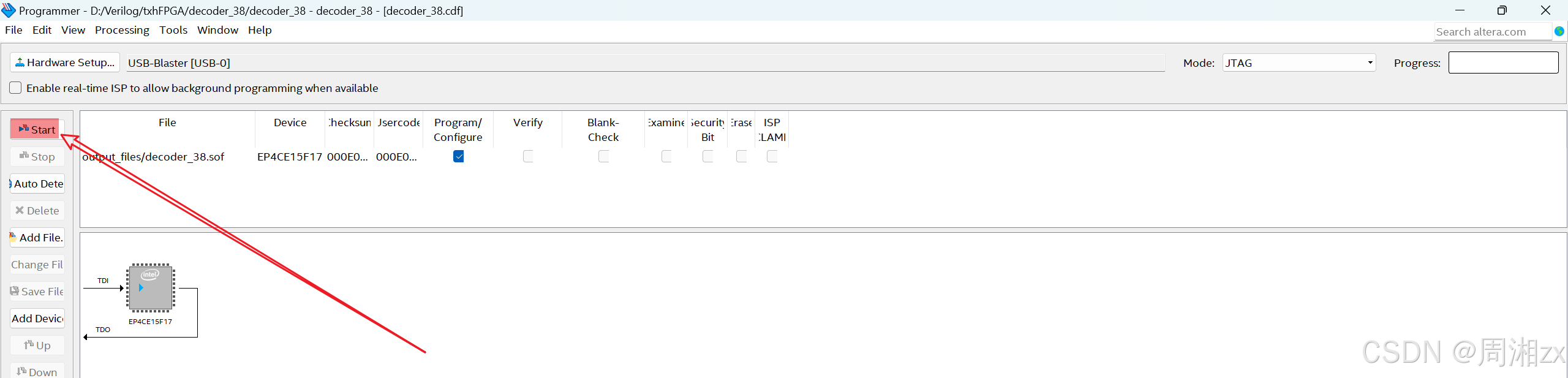
再单击左侧的"Start"项。
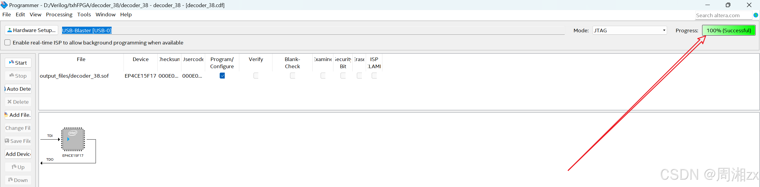
当右侧的"Process"栏显示为100%,则表示编程成功。
三、板载测试
板载测试就是由三个按键产生000~111共8组输入信号,通过指示灯的亮与灭判断3-8译码器输出的准确性。
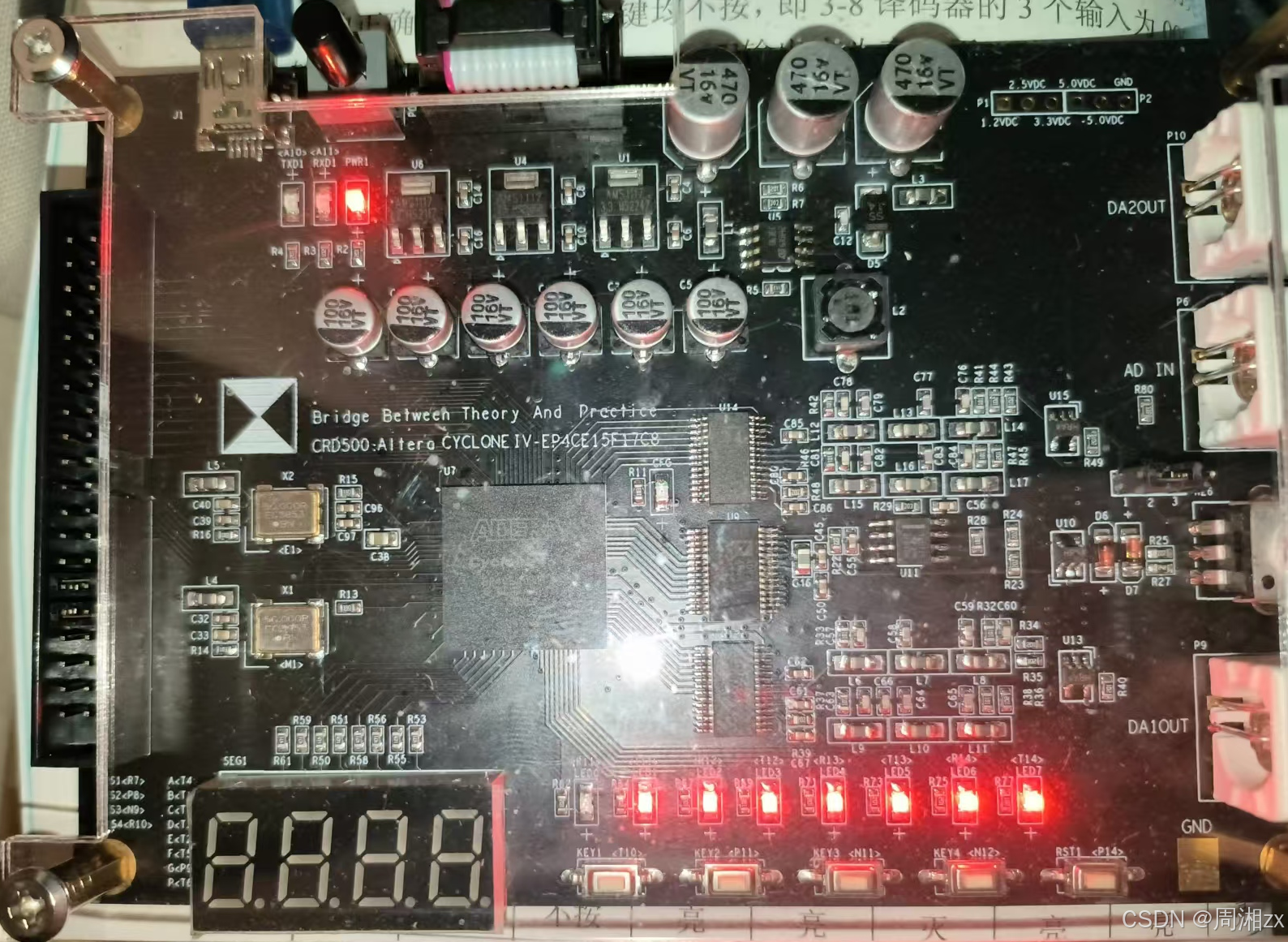
当未按键时,key_in=000,此时译码器输出"11111110",即LED0=0(LED1灭,其余亮)
当按下key1时,key_in=001,此时LED2=0(LED1灭,其余亮)
......
当同时按下key1、 key2、 key3,key_in=111,此时译码器输出"01111111",即LED7灭,其余亮。
板载测试结果如上表结论一致,由此验证了3-8译码器输出的准确性,至此该项目完成!