文章目录
- 前言
- 一、板载资源介绍
- 二、具体步骤
-
- [1. 确定红外接收头引脚编号](#1. 确定红外接收头引脚编号)
- [2. 下载infrared软件包](#2. 下载infrared软件包)
- [3. 配置infrared软件包](#3. 配置infrared软件包)
- [4. 打开STM32CubeMX进行相关配置](#4. 打开STM32CubeMX进行相关配置)
-
- [4.1 使用外部高速时钟,并修改时钟树](#4.1 使用外部高速时钟,并修改时钟树)
- [4.2 打开定时器16(定时器根据自己需求调整)](#4.2 打开定时器16(定时器根据自己需求调整))
- [4.3 打开串口](#4.3 打开串口)
- [4.4 生成工程](#4.4 生成工程)
- [5. 打开HWTIMER设备驱动](#5. 打开HWTIMER设备驱动)
- [6. 配置定时器](#6. 配置定时器)
- [7. 编译,烧录](#7. 编译,烧录)
前言
本文采用开发板为STM32L475VET6(潘多拉开发板),使用RT_Thread Studio基于芯片开发模式,完成红外遥控接收实验
一、板载资源介绍


二、具体步骤
1. 确定红外接收头引脚编号
STM32L475VET6(潘多拉开发板)红外接收头对应的引脚为PB1,17号,可参考工程项目中的drv.gpio.c确定

2. 下载infrared软件包
使用NEC协议

3. 配置infrared软件包
这里的定时器作者试过timer16可以,timer3不可以

4. 打开STM32CubeMX进行相关配置
4.1 使用外部高速时钟,并修改时钟树


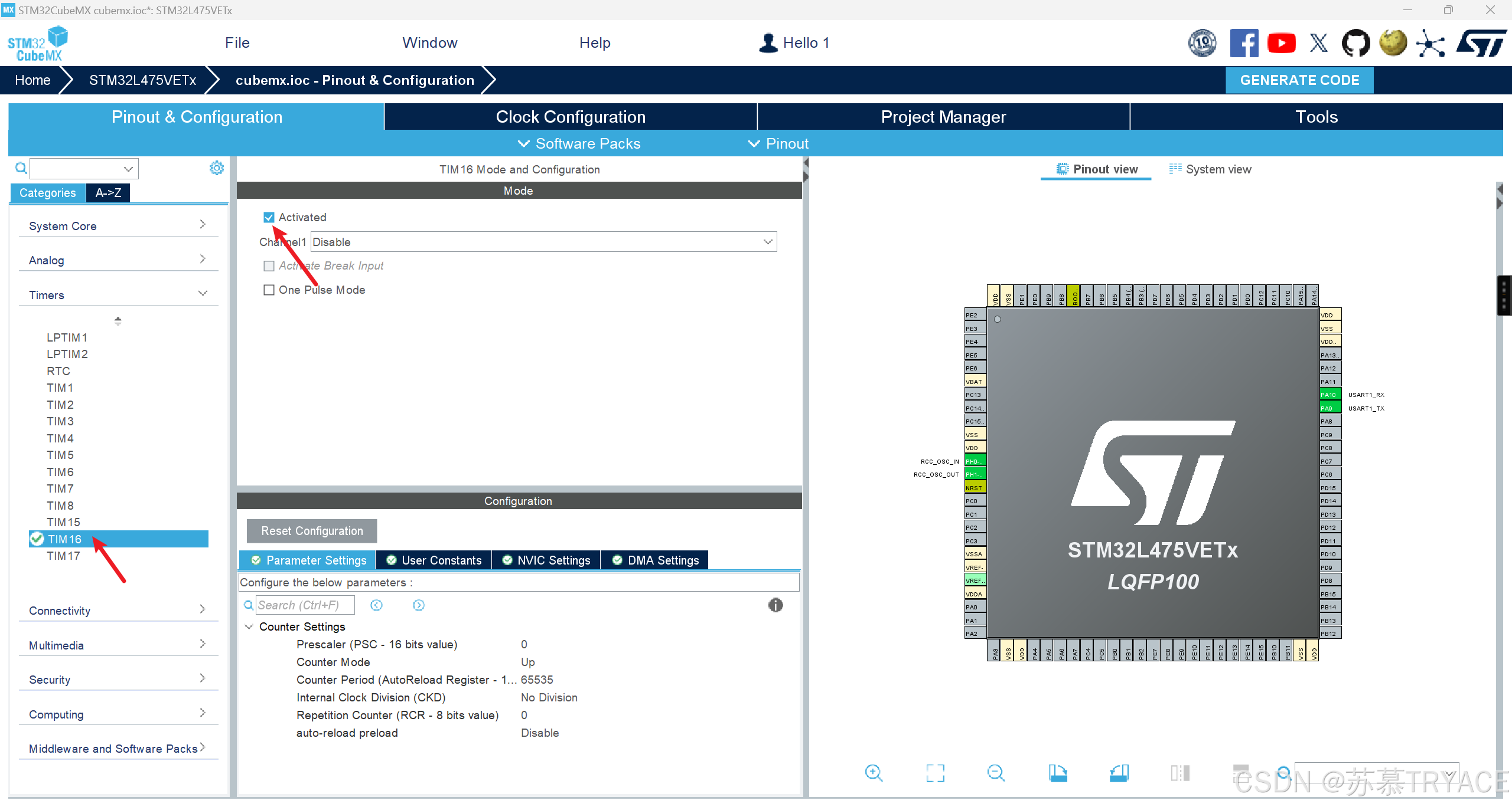
4.2 打开定时器16(定时器根据自己需求调整)
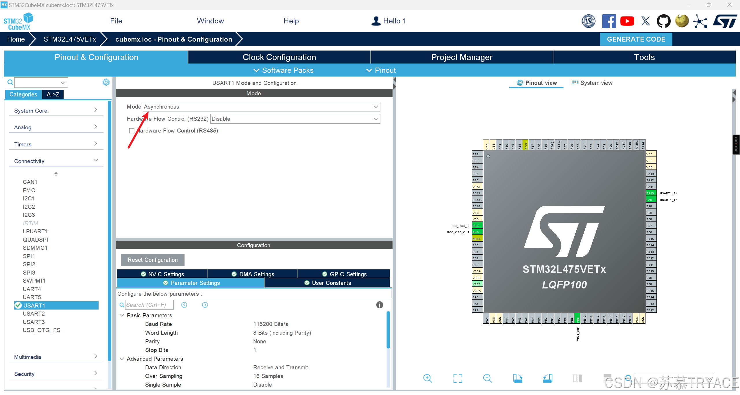
4.3 打开串口
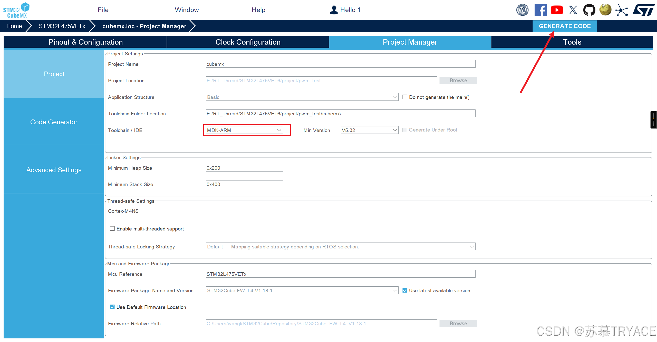
4.4 生成工程
5. 打开HWTIMER设备驱动
在RT-Thread Setting的组件栏中

6. 配置定时器
7. 编译,烧录
测试代码
cpp
#include <rtthread.h>
#include <rtdevice.h>
#include <board.h>
#include "decoder.h"

/* defined the LED0 pin: PE7 */
#define LEDG    GET_PIN(E, 8)

int main(void)
{
    int count = 1;
    /* set LED0 pin mode to output */
    rt_pin_mode(LEDG, PIN_MODE_OUTPUT);

    rt_pin_write(LEDG, PIN_HIGH);
    struct infrared_decoder_data Tdata;
    ir_select_decoder("nec");
    while (count++)
    {
        if(infrared_read("nec", &Tdata)==RT_EOK){
            rt_pin_write(LEDG, PIN_LOW);
            HAL_Delay(200);
            printf("recive:  addr:0x%02X key:0x%02X repeat:%d \n",
                    Tdata.data.nec.addr,Tdata.data.nec.key,Tdata.data.nec.repeat);
        }
        rt_pin_write(LEDG, PIN_HIGH);
    }

    return RT_EOK;
}
按下遥控器,终端会有显示
