一、实验目的
-
完成网络设备(路由器 R1-R5、PC1-PC4)的 IP 地址规划与配置,确保接口通信基础正常。
-
配置链路层协议及认证:R1 与 R5 采用 PPP 的 PAP 认证(R5 为主认证方),R2 与 R5 采用 PPP 的 CHAP 认证(R5 为主认证方),R3 与 R5 采用 HDLC 封装。
-
实现隧道配置:R1、R2、R3 构建 MGRE 环境(R1 为中心站点),R1 与 R4 构建点到点 GRE 隧道。
-
配置 RIP 路由协议,实现私有网络全网可达。
-
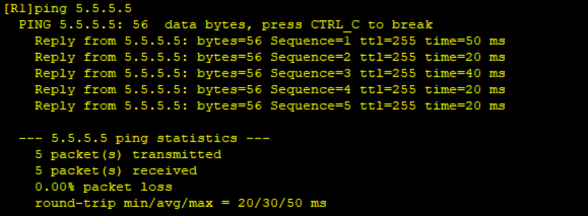
配置 NAT(Easy IP),使所有 PC 以私有 IP 为源 IP 访问 R5 的环回接口(5.5.5.5/24)。
二、实验环境
-
设备:路由器 R1、R2、R3、R4、R5(R5 作为 ISP);PC1、PC2、PC3、PC4。
-
接口类型:GigabitEthernet(GE,千兆以太网接口)、Serial(串行接口,用于广域网连接)、LoopBack(环回接口)。
-
协议:PPP(PAP/CHAP 认证)、HDLC、GRE、MGRE、RIP v2、NAT。
三、实验拓扑与地址规划
1. 拓扑图
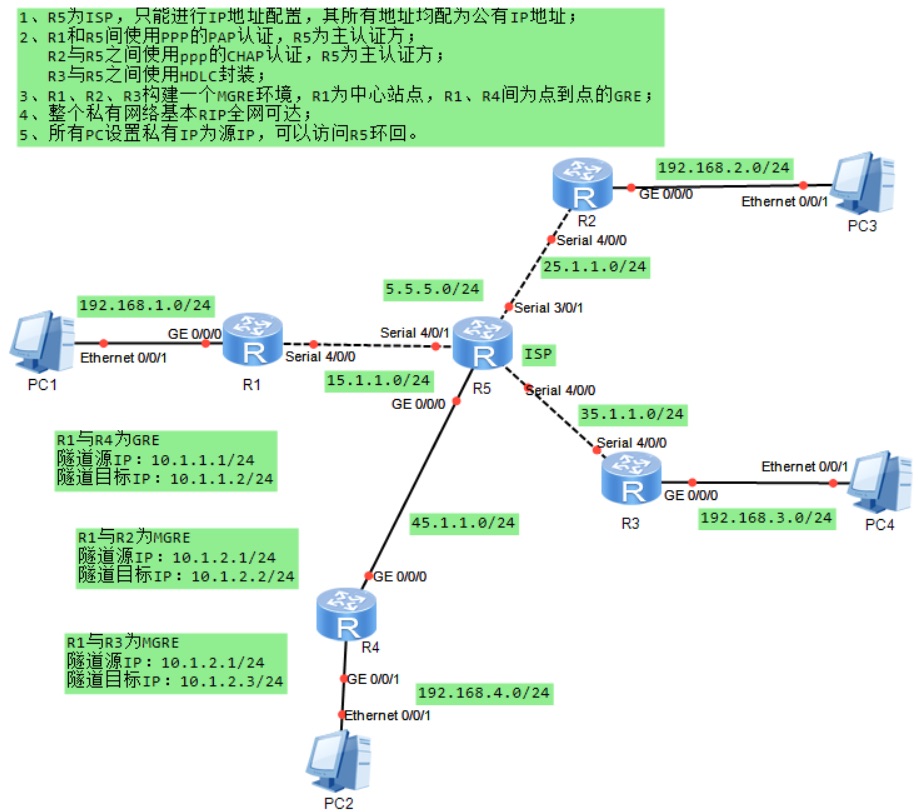
2. 地址规划表
| 设备 | 接口 | IP 地址 / 子网掩码 | 对应网段 |
|---|---|---|---|
| R1 | GE0/0/0 | 192.168.1.254/24 | 192.168.1.0/24(私有) |
| R1 | Serial4/0/0 | 15.1.1.1/24 | 15.1.1.0/24(公有) |
| R1 | Tunnel0/0/0(GRE) | 10.1.1.1/24 | 10.1.1.0/24(隧道私有) |
| R1 | Tunnel0/0/1(MGRE) | 10.1.2.1/24 | 10.1.2.0/24(隧道私有) |
| R2 | GE0/0/0 | 192.168.2.254/24 | 192.168.2.0/24(私有) |
| R2 | Serial4/0/0 | 25.1.1.2/24 | 25.1.1.0/24(公有) |
| R2 | Tunnel0/0/1(MGRE) | 10.1.2.2/24 | 10.1.2.0/24(隧道私有) |
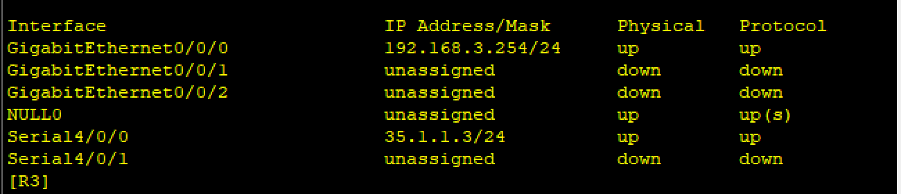
| R3 | GE0/0/0 | 192.168.3.254/24 | 192.168.3.0/24(私有) |
| R3 | Serial4/0/0 | 35.1.1.3/24 | 35.1.1.0/24(公有) |
| R3 | Tunnel0/0/1(MGRE) | 10.1.2.3/24 | 10.1.2.0/24(隧道私有) |
| R4 | GE0/0/0 | 192.168.4.254/24 | 192.168.4.0/24(私有) |
| R4 | GE0/0/1 | 45.1.1.4/24 | 45.1.1.0/24(公有) |
| R4 | Tunnel0/0/0(GRE) | 10.1.1.4/24 | 10.1.1.0/24(隧道私有) |
| R5(ISP) | LoopBack0 | 5.5.5.5/24 | 5.5.5.0/24(公有) |
| R5 | Serial4/0/1 | 15.1.1.5/24 | 15.1.1.0/24(公有) |
| R5 | Serial3/0/1 | 25.1.1.5/24 | 25.1.1.0/24(公有) |
| R5 | Serial4/0/0 | 35.1.1.5/24 | 35.1.1.0/24(公有) |
| R5 | GE0/0/0 | 45.1.1.5/24 | 45.1.1.0/24(公有) |
| PC1 | Ethernet0/0/1 | 192.168.1.1/24 | 192.168.1.0/24(私有) |
| PC2 | Ethernet0/0/1 | 192.168.4.2/24 | 192.168.4.0/24(私有) |
| PC3 | Ethernet0/0/1 | 192.168.2.3/24 | 192.168.2.0/24(私有) |
| PC4 | Ethernet0/0/1 | 192.168.3.4/24 | 192.168.3.0/24(私有) |
四、实验步骤
第一步:IP 地址配置与静态路由
1. R1-R4 的 IP 配置
以 R1 为例,其余设备配置逻辑相同:
bash
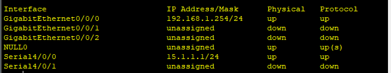
[R1]int g 0/0/0
[R1-GigabitEthernet0/0/0]ip add 192.168.1.254 24
[R1-GigabitEthernet0/0/0]int s 4/0/0
[R1-Serial4/0/0]ip add 15.1.1.1 24
R2-R4 关键配置:
-
R2:GE0/0/0(192.168.2.254/24)、Serial4/0/0(25.1.1.2/24)
-
R3:GE0/0/0(192.168.3.254/24)、Serial4/0/0(35.1.1.3/24)
-
R4:GE0/0/0(192.168.4.254/24)、GE0/0/1(45.1.1.4/24)
2.R5(ISP)的 IP 配置
bash
[ISP]int l 0
[ISP-LoopBack0]ip add 5.5.5.5 24
[ISP-LoopBack0]q
[ISP]int s 4/0/1
[ISP-Serial4/0/1]ip add 15.1.1.5 24

[ISP-Serial4/0/1]int s 3/0/1
[ISP-Serial3/0/1]ip add 25.1.1.5 24

[ISP-Serial3/0/1]int s 4/0/0
[ISP-Serial4/0/0]ip add 35.1.1.5 24

[ISP-Serial4/0/0]int g 0/0/0
[ISP-GigabitEthernet0/0/0]ip add 45.1.1.5 24
3. 静态路由配置(默认路由)
目的:使私有网络通过 R5 访问公网(R5 环回)
bash
[R1]IP route-static 0.0.0.0 0 15.1.1.5
[R2]IP route-static 0.0.0.0 0 25.1.1.5
[R3]IP route-static 0.0.0.0 0 35.1.1.5
[R4]IP route-static 0.0.0.0 0 45.1.1.5 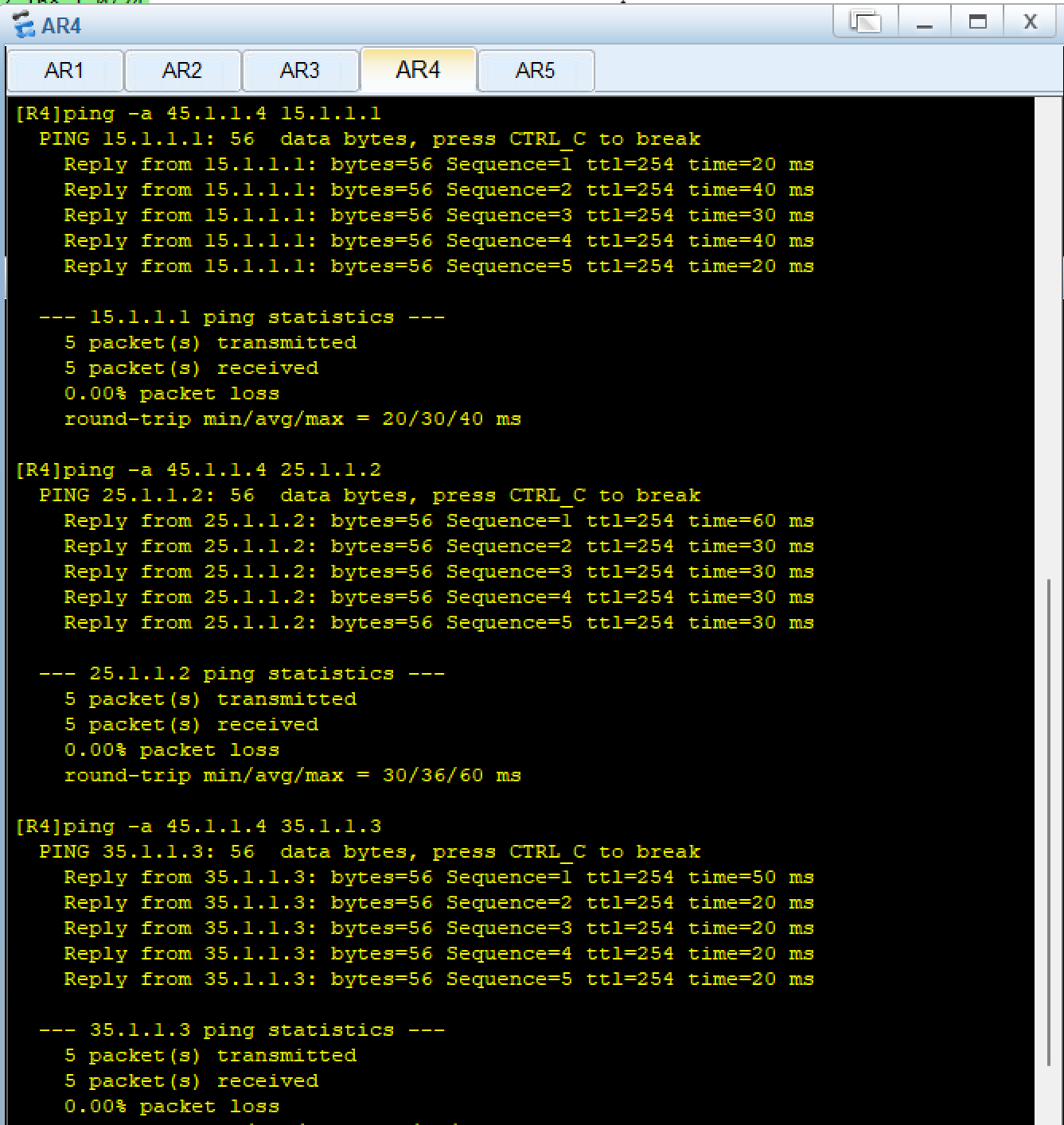
第二步:链路层协议与认证配置
1. R1-R5(PAP 认证,R5 为主认证方)
bash
[ISP]aaa
[ISP-aaa]local-user yu password cipher 12345 privilege level 15
Info: Add a new user.
[ISP-aaa]local-user yu service-type ppp
[ISP-aaa]q
[ISP]int s 4/0/1
[ISP-Serial4/0/1]link-protocol ppp
[ISP-Serial4/0/1]ppp authentication-mode pap
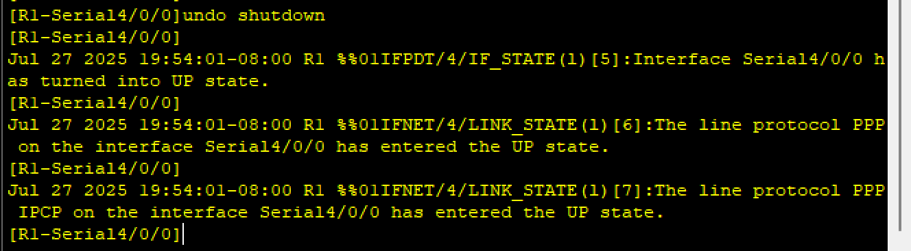
[R1]int s 4/0/0
[R1-Serial4/0/0]link-protocol ppp
[R1-Serial4/0/0]ppp pap local-user yu password cipher 12345- 验证pap认证如下,或者用
dis ppp int s 4/0/0查看认证的状态
2. R2-R5(CHAP 认证,R5 为主认证方)
R5用户已在aaa 中创建,直接启用 CHAP
shell
[ISP]int s 3/0/1
[ISP-Serial3/0/1]ppp authentication-mode chap

[R2]int s 4/0/0
[R2-Serial4/0/0]ppp chap user yu
[R2-Serial4/0/0]ppp chap password cipher 12345- 验证chap(同pap认证)
3. R3-R5(HDLC 封装)
bash
[ISP]int s 4/0/0
[ISP-Serial4/0/0]link-protocol hdlc

[R3]int s 4/0/0
[R3-Serial4/0/0]link-protocol hdlc - 验证
第三步:隧道配置
1. R1-R4(点到点 GRE 隧道)
bash
[R1]int t 0/0/0
[R1-Tunnel0/0/0]ip add 10.1.1.1 24
[R1-Tunnel0/0/0]tunnel-protocol gre
[R1-Tunnel0/0/0]source 15.1.1.1
[R1-Tunnel0/0/0]description 45.1.1.4

[R4]int t 0/0/0
[R4-Tunnel0/0/0]ip add 10.1.1.4 24
[R4-Tunnel0/0/0]tunnel-protocol gre
[R4-Tunnel0/0/0]source 45.1.1.4
[R4-Tunnel0/0/0]description 15.1.1.1
2. R1-R2-R3(MGRE 隧道,R1 为中心)
bash
[R1]int Tunnel 0/0/1
[R1-Tunnel0/0/1]ip add 10.1.2.1 24
[R1-Tunnel0/0/1]tunnel-protocol gre p2mp
[R1-Tunnel0/0/1]source 15.1.1.1
[R1-Tunnel0/0/1]nhrp network-id 100
[R1-Tunnel0/0/1]nhrp entry multicast dynamic
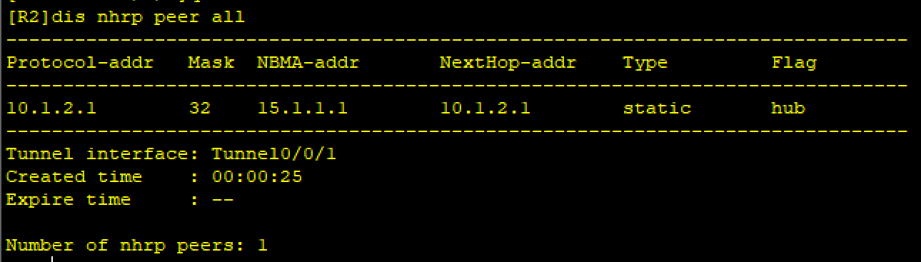
[R2]int Tunnel 0/0/1
[R2-Tunnel0/0/1]ip add 10.1.2.2 24
[R2-Tunnel0/0/1]tunnel-protocol gre p2mp
[R2-Tunnel0/0/1]source serial 4/0/0
[R2-Tunnel0/0/1]nhrp network-id 100
[R2-Tunnel0/0/1]nhrp entry 10.1.2.1 15.1.1.1 register
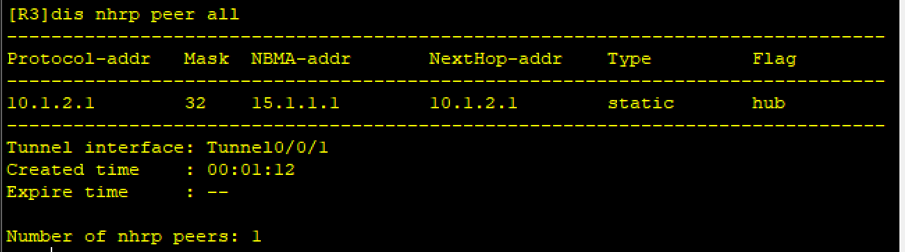
[R3]int Tunnel 0/0/1
[R3-Tunnel0/0/1]ip add 10.1.2.3 24
[R3-Tunnel0/0/1]tunnel-protocol gre p2mp
[R3-Tunnel0/0/1]source serial 4/0/0
[R3-Tunnel0/0/1]nhrp network-id 100
[R3-Tunnel0/0/1]nhrp entry 10.1.2.1 15.1.1.1 register 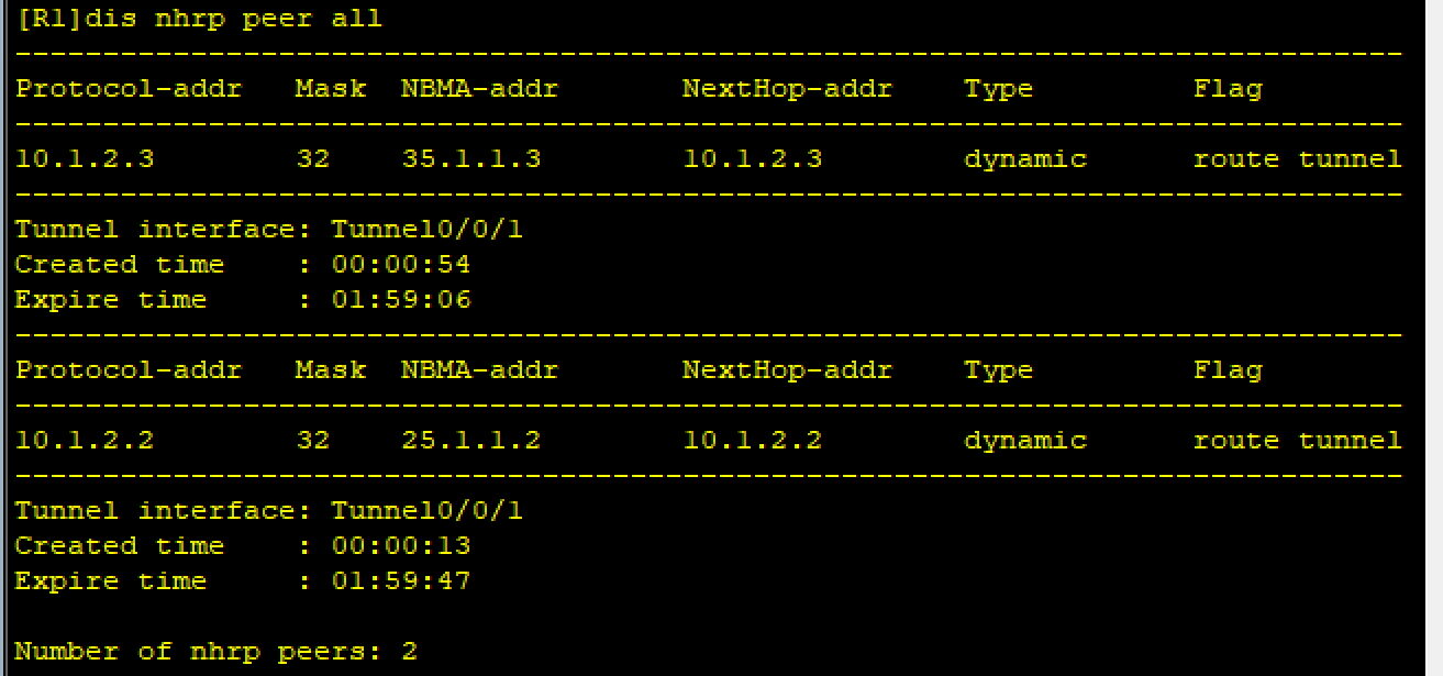
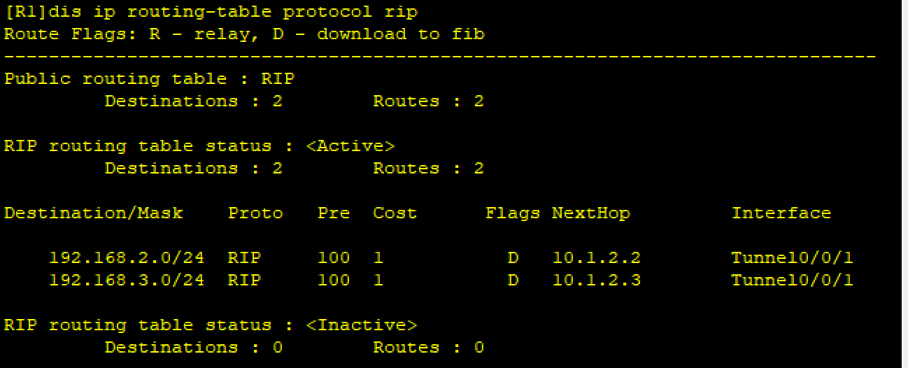
第四步:RIP 路由配置(私有网络全网可达)
1. 启用 RIP v2 并宣告网络
bash
[R1]rip 1
[R1-rip-1]version 2
[R1-rip-1]undo summary
[R1-rip-1]network 192.168.1.0
[R1-rip-1]network 10.0.0.0 #A类地址,只关注前八位
R2、R3、R4步骤同理
- 验证
2. 关闭 MGRE 隧道水平分割
MGRE 为多点接口,水平分割会阻止路由转发,需关闭:
bash
[R1-Tunnel0/0/1]undo rip split-horizon 验证:
第五步:NAT 配置(Easy IP)
目的:将私有 IP 转换为出口公网 IP,实现 PC 访问 R5 环回(5.5.5.5)。
以 R1 为例,其余设备配置逻辑相同:
bash
[R1]acl 2000
[R1-acl-basic-2000]rule permit source 192.168.1.0 0.0.0.255
[R1-acl-basic-2000]int s 4/0/0
[R1-Serial4/0/0]nat outbound 2000
R2、R3、R4同理
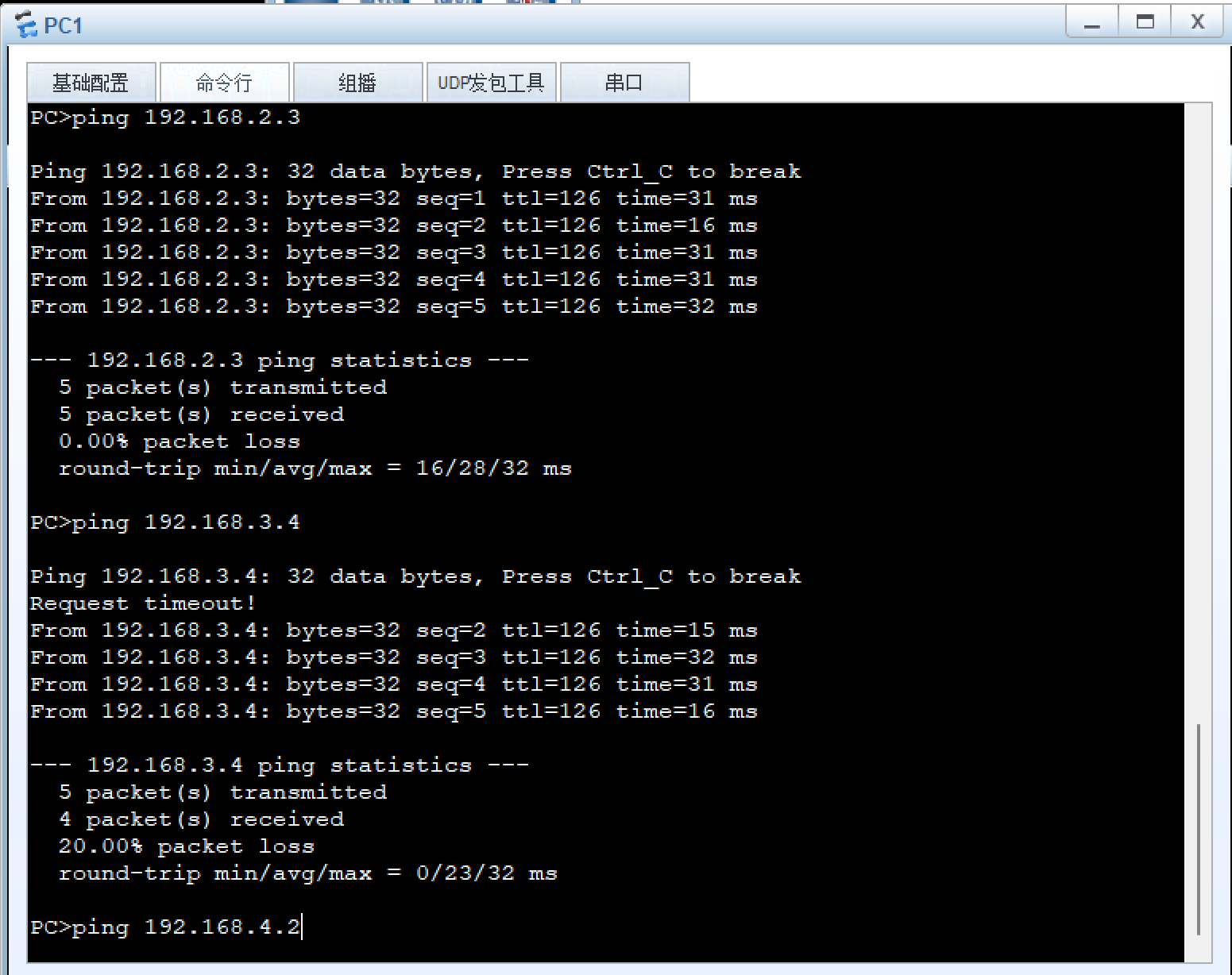
验证:
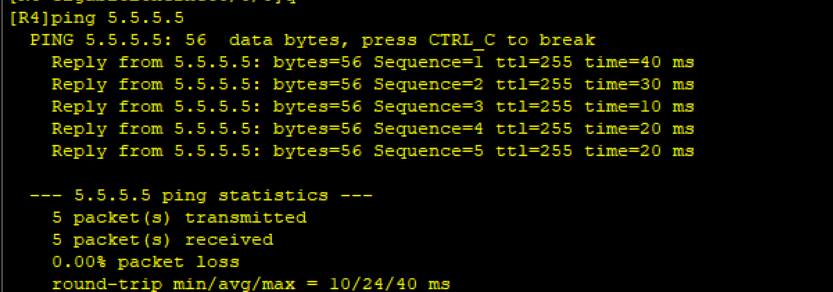
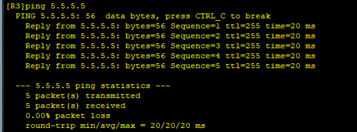
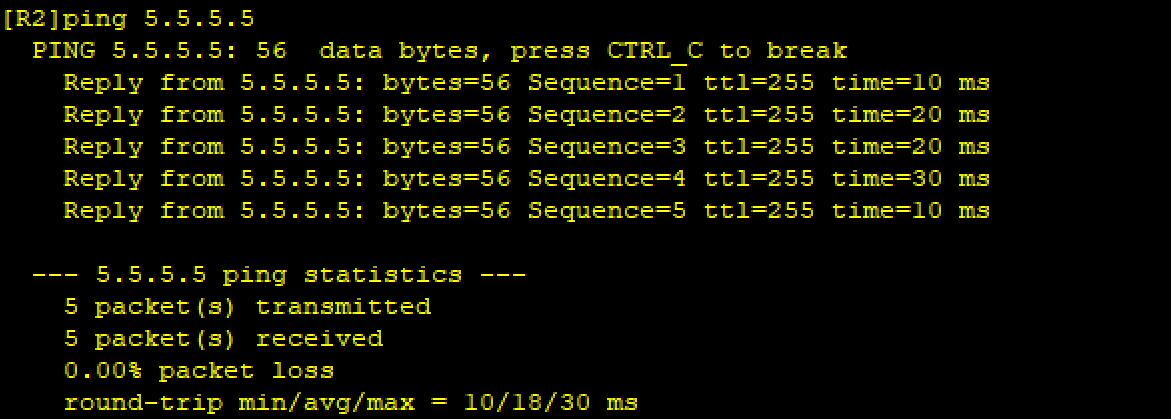
五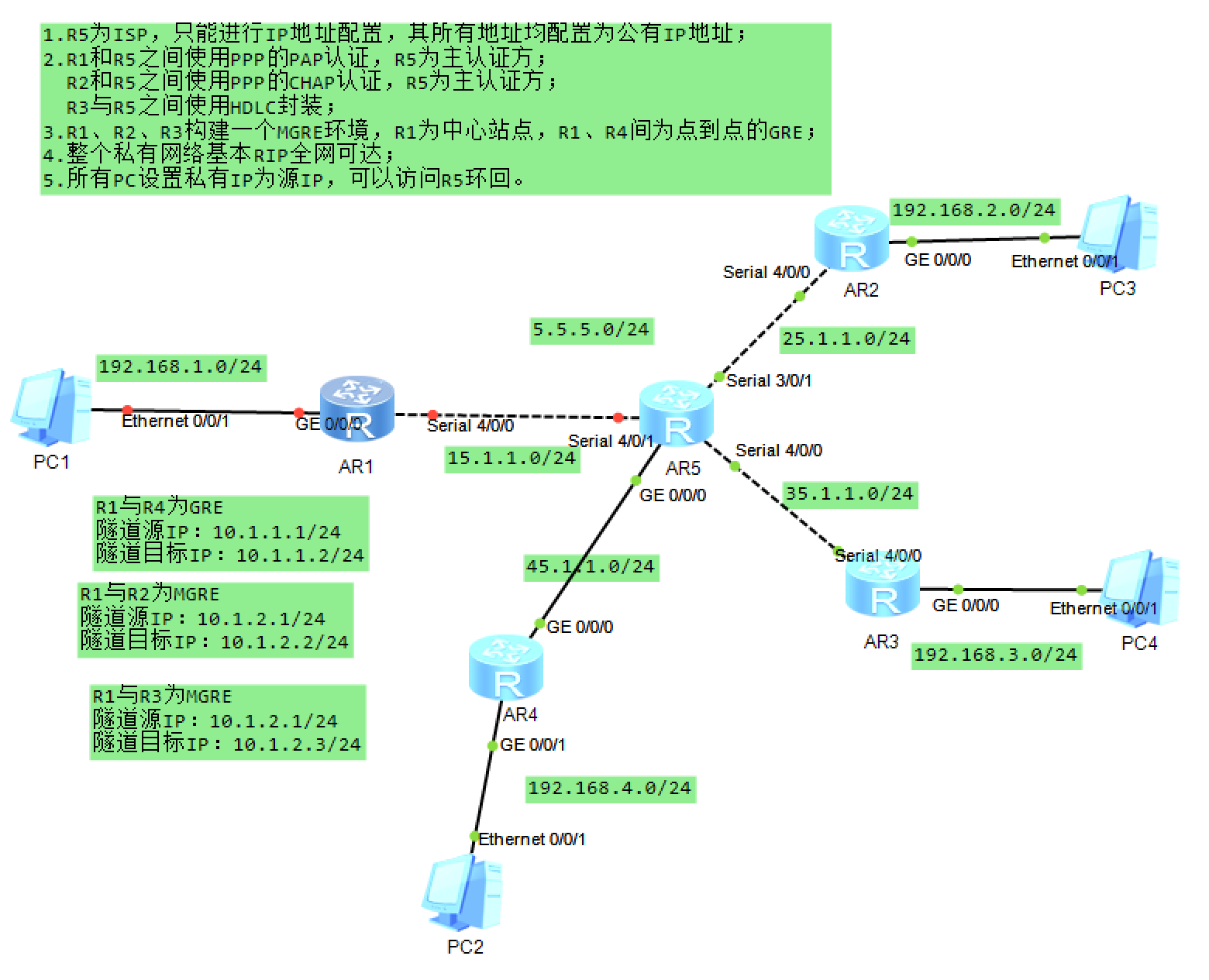
、实验总结
本次实验完成了网络分层配置,包括 IP 规划、链路层认证、隧道搭建、动态路由及 NAT 转换,实现了私有网络内部互通及访问公网服务的目标。关键难点在于 MGRE 隧道的 NHRP 注册和 RIP 水平分割的处理,通过逐步验证每一步配置,确保了整体网络的连通性。