0x00 前言
从上篇博客发出到现在已经过了一年多了,之前挖的坑一直都没有填,做事都要有始有终,所有才有了这一篇博客
本文涉及的内容主要有:
- 描边
- 边缘光
由于涉及到的知识点很多,本文并不会详细的介绍,不清楚的知识点需要各位读者去查阅相关资料补一补,欢迎点赞收藏和评论,有疑问或不同意见可以私信或者在评论讨论,话不多说,我们直接进入正题。
0x01 描边
在描边这块常用的有四种方案分别是 1.BackSide描边 2.后处理描边 3.模板测试描边 4.菲涅尔描边,笔者这里采用的是第一种方式也就是BackSide配合法线外扩的方式,为什么要选择这种方式呢,主要是考虑到以下几个原因,BackSide的这种方式比较简单粗暴,且效果相对于后处理和模板测试的方案来说,比较稳定可控,看起来的效果比较好,但这种方式也有缺点,缺点就是需要clone一遍模型,会有额外的drawcall和三角面,有额外的性能消耗,但我们可以通过一些trick来优化,减少性能消耗
遍历克隆后的模型替换他的材质并设置背面渲染,这里为了节省性能我们可以选择使用MeshBasicMaterial或者是ShaderMaterial,为了避免Z-fighting可以稍微给放大一点点,
tsx
    outlineModel.traverse((child) => {
      if (child instanceof Mesh) {
        const mat = new CustomShaderMaterial({
          baseMaterial: MeshBasicMaterial,
          uniforms: outlineUniforms,
          vertexShader: outlineVertexShader,
          fragmentShader: outlineFragmentShader,
          side: BackSide,
          vertexColors: true,
          silent: true,
          map: child.material.map,
          transparent: false,
          alphaTest: child.material.alphaTest,
        })
        child.material = mat
      }
    })
    outlineModel.scale.setScalar(1.0001)
outlineModel.position.copy(ayakaRef.current!.position)也许有的读者看到这会有这么一个想法,我直接克隆一份模型,并且将他稍微放大一点,设置背面渲染,颜色给黑色不就可以了吗,由于我们希望这个描边是等宽的,且因为受到透视投影的影响,近大远小,就导致当摄像机离backside的模型很近时,描边会显得很宽很大,拉远了又很小,基本上看不到,这样视觉效果就不是很好了,所以会使用到的trick是在裁剪空间沿法线方向进行外扩,之所以选择在裁剪空间外扩的目的就是,我们在顶点着色器中是无法直接访问当ndc空间下的数据,经过mvp变换后在经过透视除法才会转换到ndc空间中,透视除法会自动进行,顶点经过mvp变换后会被变换到裁剪空间,裁剪空间的值域是[-w,w], 只需要除以w就可以得到在ndc空间下的表示了,后续会通过透视除法和视口变换把顶点从裁剪空间变换到屏幕空间,所以我们只需要在ndc空间中固定其描边的宽度,因为会自动进行透视除法(也就是除以w)所以我们需要再ndc空间也保持一个固定的数值就需要乘以w,这里需要注意的是由于ndc空间中宽高比为1:1,旦窗口宽高比可不一定是这个值,为了避免出现宽度不统一的问题,需要根据窗口的宽高比再进行修正,就可以实现等宽的描边了,代码如下
glsl
attribute vec4 tangent;
attribute vec3 _uv7;
uniform float uOutLineWidth;
uniform vec2 uResolution;
varying vec3 vNor;
varying vec2 vUv;
varying float uOpacity;

void main() {
  vec3 trans = position;
  vec4 clipPosition = projectionMatrix * modelViewMatrix * vec4(trans, 1.0);
  vec3 viewNormal = normalize(normalMatrix * normal);
  vec4 clipNormal = projectionMatrix * vec4(viewNormal, 0.0);
  vec3 ndcNormal = clipNormal.xyz;
  float aspect = abs(uResolution.y / uResolution.x);
  clipNormal.x *= aspect;
  /* in Opengl clip space w = -zView  */
  clipPosition.xy += 0.01 * uOutLineWidth * ndcNormal.xy * clipPosition.w;
  csm_PositionRaw = clipPosition;
  vUv = uv;
}
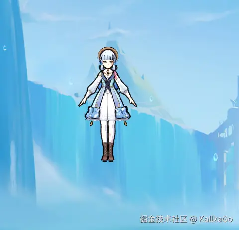
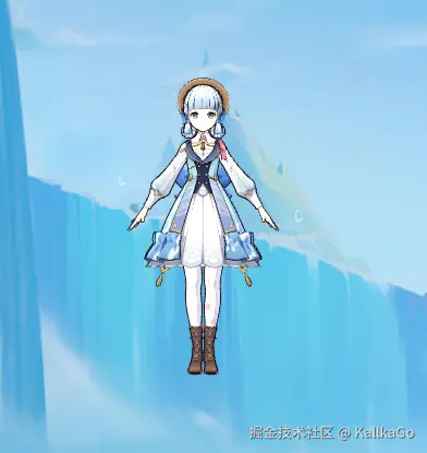
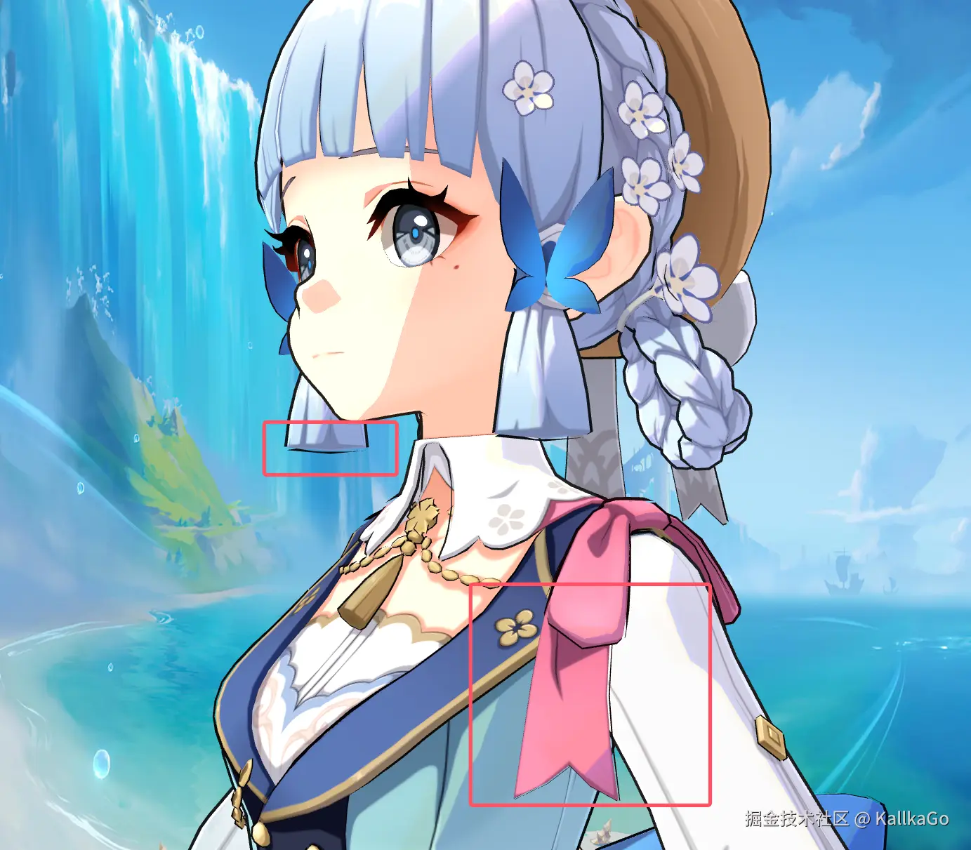
可以看到在
1.脸部出现了多余的描边
2.一些地方描边似乎已经断开了
针对一个问题,我们可以使用模型的顶点色的alpha通道,这个通道存了描边的阈值,也就是那些地方需要描边。哪些地方不需要描边,把视角拉远后发现描边太突出了,由于是固定宽度,模型占的像素越来越少,但是描边一直都是占那么多像素,给人一种描边在放大的错觉,这里可以对裁剪空间的w做一个钳制
钳制前
钳制后
glsl
float ctrlCSw = clamp(clipPosition.w, .5, 3.);
clipPosition.xy += 0.01 * uOutLineWidth * ndcNormal.xy * color.a * ctrlCSw;
对于第二个问题在变换很大的锋利边缘处使用法线外扩的这种方案就会出现描边断裂的问题,其原因是转折处的法线方向不一致
基本的解决思路是将相同索引&相同位置点 的法线(需转换到切线空间下)进行平滑处理,笔者这里是写了一个小工具离线计算了平滑法线并且存入到uv7里,核心代码如下(有很多可以优化的地方)
ts
function writeAverageNormalToAttribute (mesh) {
  return new Promise((resolve, reject) => {
    const averageNormalHash = new Map()
    const position = mesh.geometry.attributes.position
    const tangents = mesh.geometry.attributes.tangent
    const normal = mesh.geometry.attributes.normal
    const uv7 = mesh.geometry.getAttribute('_uv7')

    if (uv7) {
      console.log('_uv7 already exists, deleting it')
      mesh.geometry.deleteAttribute('_uv7')
    }

    if (!tangents) {
      return reject(new Error('No tangents found'))
    }
    if (!normal) {
      return reject(new Error('No normal found'))
    }
    if (!position) {
      return reject(new Error('No position found'))
    }

    for (let j = 0; j < position.count; j++) {
      const vertex = new THREE.Vector3().fromBufferAttribute(position, j)
      const norm = new THREE.Vector3().fromBufferAttribute(normal, j)

      const key = `${vertex.x},${vertex.y},${vertex.z}`
      if (!averageNormalHash.has(key)) {
        averageNormalHash.set(key, norm)
      } else {
        const avgNorm = averageNormalHash.get(key)
        avgNorm.add(norm).normalize()
        averageNormalHash.set(key, avgNorm)
      }
    }

    const averageNormals = []
    for (let j = 0; j < position.count; j++) {
      const vertex = new THREE.Vector3().fromBufferAttribute(position, j)
      const key = `${vertex.x},${vertex.y},${vertex.z}`
      averageNormals.push(averageNormalHash.get(key))
    }

    const avgNormals = new Float32Array(position.count * 3)
    for (let j = 0; j < position.count; j++) {
      const avgNorm = averageNormals[j]
      const nor = new THREE.Vector3().fromBufferAttribute(normal, j)
      const tangent = new THREE.Vector4().fromBufferAttribute(tangents, j)
      const tangentVec3 = new THREE.Vector3(tangent.x, tangent.y, tangent.z)
      tangentVec3.normalize()
      const bitangent = nor.clone().cross(tangentVec3).multiplyScalar(tangent.w)
      bitangent.normalize()

      /*
      in threejs

      https://threejs.org/docs/index.html#api/zh/math/Matrix3

      in glsl

      https://relativity.net.au/gaming/glsl/Variables.html
      */


      const tbnMatrix = new THREE.Matrix3().set(
        tangent.x, bitangent.x, nor.x,
        tangent.y, bitangent.y, nor.y,
        tangent.z, bitangent.z, nor.z
      )

      //wToT = the inverse of tToW = the transpose of tToW as long as tToW is an orthogonal matrix
      tbnMatrix.invert()

      const smoothNormal = avgNorm.clone().applyMatrix3(tbnMatrix).normalize()
      avgNormals[j * 3] = smoothNormal.x
      avgNormals[j * 3 + 1] = smoothNormal.y
      avgNormals[j * 3 + 2] = smoothNormal.z
    }
    /*
    The custom attribute in GLTFExporter will be prefixed with "_", e.g. "_uv7" in the case of "uv7" attribute.

    See:
    https://github.com/mrdoob/three.js/blob/dcb30fd11276a14255155f3cb6eb3345622c9aef/examples/jsm/exporters/GLTFExporter.js#L1727

    */
    mesh.geometry.setAttribute('uv7', new THREE.BufferAttribute(avgNormals, 3))
    return resolve('done')
  })
}
离线计算了平滑法线后,我们需要再顶点着色器中构建tbn矩阵,利用基变换把存储于切线空间中的法线变换到目标空间,后续转换到裁剪空间,在裁剪空间沿法线方向外扩

完整代码如下
glsl
attribute vec4 tangent;
attribute vec3 _uv7;
uniform float uOutLineWidth;
uniform vec2 uResolution;
varying vec3 vNor;
varying vec2 vUv;
varying float uOpacity;

void main() {
  vec3 tansTangent = normalize(tangent.xyz);
  vec3 bitangent = normalize(cross(normal, tansTangent) * tangent.w);
  mat3 tbn = mat3(tansTangent, bitangent, normal);
  vec3 aveNormal = normalize(tbn * _uv7);
  vec3 trans = position;
  vec4 clipPosition = projectionMatrix * modelViewMatrix * vec4(trans, 1.0);
  vec3 viewNormal = normalize(normalMatrix * aveNormal);
  vec4 clipNormal = projectionMatrix * vec4(viewNormal, 0.0);
  vec3 ndcNormal = clipNormal.xyz;
  float aspect = abs(uResolution.y / uResolution.x);
  clipNormal.x *= aspect;
  /* in Opengl clip space w = -zView  */
  float ctrlCSw = clamp(clipPosition.w, .5, 3.);
  clipPosition.xy += 0.01 * uOutLineWidth * ndcNormal.xy * color.a * ctrlCSw;
  // clipPosition.z += 0.0001 * ndcNormal.z;
  csm_PositionRaw = clipPosition;
  vNor = aveNormal;
  vUv = uv;
}
0x02 边缘光
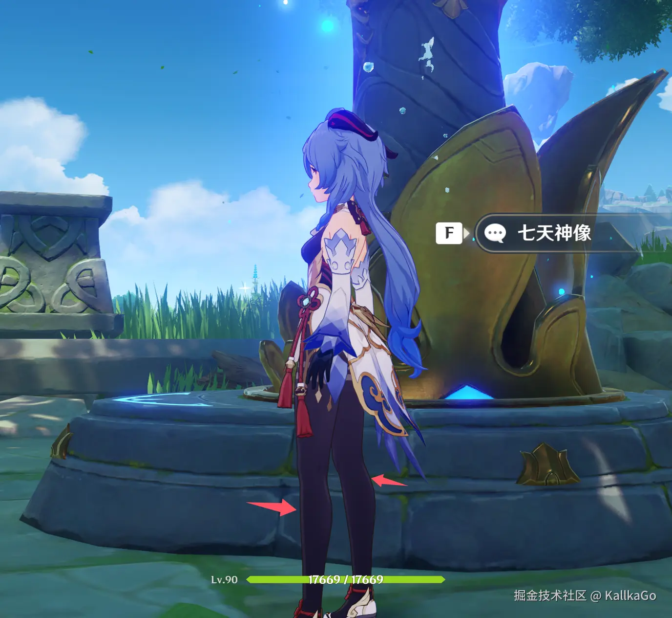
在游戏中不管镜头推近还是拉远,边缘光相对于模型始终是等宽的
边缘光常见的有两种方案
- 菲涅尔边缘光
- 屏幕空间边缘光
对于第一种使用菲涅尔的边缘光,由于菲涅尔的计算需要法线的参与,因此,效果的好坏受到模型的影响,不可控,这种做法不合适
对于屏幕空间边缘光,我们第一步需要做的是检测边缘,边缘检测的算法太多太多了,比如在CV领域最常用的Sobel算子,或是类似的Robert算子都可以实现基于图片的边缘检测。但是这些方法本质是后处理方法,可控性非常不好,就算是拿深度图做检测,也不方便控制宽度等自定义风格化的参数,所以我们这里的思路和法线外扩的描边思路类似
- 获取全局深度图
- 使用屏幕坐标映射到01采样全局深度图
- 沿摄像机空间下的法向量的xy方向偏移采样的uv坐标(使用摄像机空间下的法线是为了确保边缘光可以跟随摄像机镜头的转动)
- 偏移后采样的结果减去未偏移的结果就可以得到边缘信息了
获取全局深度图我们可以借助scene.overrideMaterial把场景中的材质都替换成MeshDepthMaterial(记得打开双面渲染),渲染到一个RT上并传入身体的片元着色器中
const
    const dpr = gl.getPixelRatio()

    rt1.depthTexture.image.width = innerWidth * dpr
    rt1.depthTexture.image.height = innerHeight * dpr
    rt1.setSize(innerWidth * dpr, innerHeight * dpr)

    const originalBg = scene.background
    scene.background ??= bgColor
    scene.overrideMaterial = material

    ignoreList.forEach(obj => {
      obj.visible = false
    })

    gl.setRenderTarget(rt1)
    gl.render(scene, camera)
    gl.setRenderTarget(null)

    scene.overrideMaterial = null
    scene.background = originalBg

    ignoreList.forEach(obj => {
      obj.visible = true
    })
在人物身体的色器中,我们需要采样获取屏幕坐标并且把屏幕坐标映射到0-1之间去采样传入的全局深度图
顶点着色器核心代码
glsl
//...
varying vec4 vScreenPos;

vec4 ComputeScreenPos(vec4 pos) {
  vec4 o = pos * 0.5;
  o.xy = vec2(o.x, o.y) + o.w;
  o.zw = pos.zw;
  return o;
}

void main() {
   //...
  vScreenPos = ComputeScreenPos(clipPos);
}
片元着色器核心代码
glsl
float readDepth(sampler2D depthSampler, vec2 coord) {
  float fragCoordZ = texture2D(depthSampler, coord).x;
  float viewZ = perspectiveDepthToViewZ(fragCoordZ, uNear, uFar);
  return viewZToOrthographicDepth(viewZ, uNear, uFar);
}
glsl
   /* Screen Pos */
  vec2 scrPos = vScreenPos.xy / vScreenPos.w;
  vec2 scrOffsetPos = scrPos + viewNormal.xy * uRimLightWidth * 0.01;

  // rimLight
  float offsetDepth = readDepth(uDepthTexture, scrOffsetPos);
  float currentDepth = readDepth(uDepthTexture, scrPos);
  float depthDiff = clamp(offsetDepth - currentDepth, 0., 1.);
  float rimIntensity = smoothstep(.12, 1., depthDiff);
  vec3 rimLight = diffuse * rimIntensity * uRimLightIntensity * fresnel;
用FOV和acpect可以把透视投影矩阵表示为如下形式
Ppersp= atan(2θ)10000tan(2θ)10000−f−nf+n000−f−n2fn−1
此时我们发现,假如视图空间下的某个点对应的齐次坐标为 (x,y,z,1),那么经过透视投影变换后,其齐次坐标应为:
r−l2n0000t−b2n0000−f−nf+n000−f−n2fn−1 xinyinzin1 = xoutyoutzout−zin
在MeshDepthMaterial源码中输出的深度是这样子定义的
glsl
float fragCoordZ = 0.5 * vHighPrecisionZW[ 0 ] / vHighPrecisionZW[ 1 ] + 0.5;vHighPrecisionZW就是裁剪空间下的Z和W分量,又因为裁剪空间下深度的值域是[-w,w],所以 MeshDepthMaterial是将非线性的深度映射到[0,1]之间并作为颜色输出,
深度图中的每个像素(或纹理坐标)包含一个深度值,表示从观察者(通常是摄像机)到场景中物体的距离。深度值通常以非线性形式表示,通常是归一化的,范围在0.0(最近处)到1.0(最远处)之间。
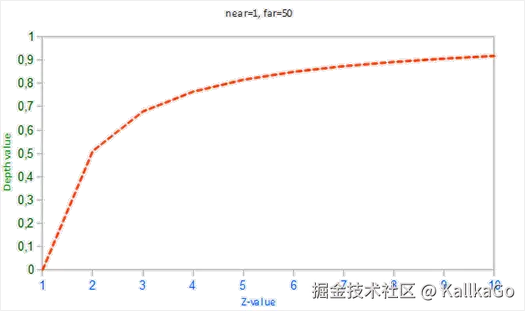
可以看到,深度值很大一部分是由很小的z值所决定的,这给了近处的物体很大的深度精度,这会造成很严重的精度问题,所以我们需要将深度线性表示并映射到[0,1],这也是readDepth这个函数所做的事
这里需要除以w的原因是ComputeScreenPos这个函数返回的值域是[0,w],所以我们需要除以w映射到[0,1]作为uv坐标去采样,这里还可以与菲涅尔相作用(也可以不加),demo效果下


0x03 后记
这篇文章到这里就结束了,目前我们还剩下后处理方面的东西,分别是Bloom和ToneMap,会在下一篇文章讲到,感谢给予我帮助的各位大佬,谢谢!