串口线A-B
1. 官方文档
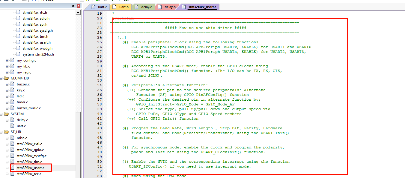
STM32官方文档《stm32f4xx_usart.c》中有具体说明
翻译:
txt
===============================================================================
#####如何使用此驱动程序#####
===============================================================================
[..]
(#)使用以下功能启用外围时钟
适用于USART1和USART6的RCC_APB2 PeriphClockCmd(RCC_APB2Periph_USARTx,启用)
RCC_APB1 PeriphClockCmd(RCC_APB1Periph_USARTx,启用)适用于USART2、USART3、,
UART4或UART5。

(#)根据USART模式,使用以下命令启用GPIO时钟
RCC_AHB1PeriphClockCmd()函数。(I/O可以是TX、RX、CTS,
或/和SCLK)。

(#)外设的备用功能:
(++)将引脚连接到所需外围设备的备用
使用GPIO_PinAFConfig()函数的功能(AF)
(++)通过以下方式在备用功能中配置所需的引脚:
GPIO_nitStruct->GPIO_Mode=GPIO_Mode_AF
(++)通过以下方式选择类型、上拉/下拉和输出速度
GPIO_uPd、GPIO_OType和GPIO_Speed成员
(++)调用GPIO_Init()函数

(#)对波特率、字长、停止位、奇偶校验、硬件进行编程
使用USART_Init()进行流量控制和模式(接收器/发射器)
功能。

(#)对于同步模式,启用时钟并编程极性,
使用USART_ClockInit()函数计算相位和最后一位。

(#)使用函数启用NVIC和相应的中断
如果需要使用中断模式,请使用USART_ITConfig()。

(#)使用DMA模式时
(++)使用DMA_Init()函数配置DMA
(++)使用USART_DMACmd()函数激活所需的通道请求

(#)使用USART_Cmd()函数启用USART。

(#)使用DMA模式时,使用DMA_Cmd()函数启用DMA。

-@-请参阅多处理器、LIN、半双工、智能卡、IrDA小节
详情请见

[..]
为了达到更高的通信波特率,可以
使用函数USART_OverSampling8Cmd()启用8模式的过采样。
启用USART时钟(RCC_APBxPeriphClockCmd())后应调用此函数
在调用函数USART_Init()之前。
整理一下,代码大致是这样的
c
void UART_Init()
{
	// 启动外围时钟
	// RCC_APB2PeriphClockCmd(); 	// 适用于USART1和USART6的
	// RCC_APB1 PeriphClockCmd(); 	// 适用于USART2、USART3、UART4或UART5。

	// 启动GPIO时钟
	// RCC_AHB1PeriphClockCmd();

	// 将引脚连接到所需外围设备的备用
	// GPIO_PinAFConfig()

	// 配置GPIO
	// GPIO_Init()

	// 对波特率、字长、停止位、奇偶校验、硬件进行编程
	// USART_Init()

	// 对于同步模式,启用时钟并编程极性
	// USART_ClockInit()

	// 使用函数启用NVIC和相应的中断
	// USART_ITConfig()

	// 使用DMA模式时
	// 使用DMA_Init()函数配置DMA
	// 使用USART_DMACmd()函数激活所需的通道请求

	// 使用USART_Cmd()函数启用USART。

	// 使用DMA模式时,使用DMA_Cmd()函数启用DMA。

}
2. 串口初始化
我这里以一个小Demo举例子,我的Demo要求是 UART1+A-A口线接收中断通信+控制蜂鸣器的响和不响。
(1) 启动外围时钟
c
RCC_APB2PeriphClockCmd(RCC_APB2Periph_USART1, ENABLE); // 适用于USART1和USART6的(2) 启动GPIO时钟
c
RCC_AHB1PeriphClockCmd(RCC_AHB1Periph_GPIOA, ENABLE);(3) 配置外设所需要的复用引脚
c
void GPIO_PinAFConfig(GPIO_TypeDef* GPIOx, uint16_t GPIO_PinSource, uint8_t GPIO_AF);文档函数介绍:
txt
/**
  * @brief  Changes the mapping of the specified pin.
  * @param  GPIOx: where x can be (A..K) to select the GPIO peripheral for STM32F405xx/407xx and STM32F415xx/417xx devices
  *                      x can be (A..I) to select the GPIO peripheral for STM32F42xxx/43xxx devices.
  *                      x can be (A, B, C, D and H) to select the GPIO peripheral for STM32F401xx devices.
  * @param  GPIO_PinSource: specifies the pin for the Alternate function.
  *         This parameter can be GPIO_PinSourcex where x can be (0..15).
  * @param  GPIO_AFSelection: selects the pin to used as Alternate function.
翻译:
txt
*@brief更改指定引脚的映射。
*@param GPIOx:其中x可以是(A..K),用于选择STM32F405xx/407xx和STM32F415xx/417xx设备的GPIO外围设备
*x可以(A..I)为STM32F42xx/43xxx设备选择GPIO外围设备。
*x可以是(A、B、C、D和H),为STM32F401xx设备选择GPIO外设。
*@param GPIO_PinSource:指定备用功能的引脚。
*此参数可以是GPIO_InSourcex,其中x可以是(0..15)。
*@param GPIO_AFS选择:选择用作备用功能的引脚。
介绍:
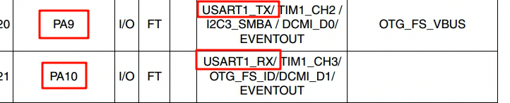
- 第一个参数:选择哪个GPIO?我这里是PA9与PA10,所以是GPIOA。
- 第二个参数:选择哪个引脚?选择引脚9与引脚10
- 第三个参数:选择引脚复用成什么功能?我这里是复用成串口1
c
GPIO_PinAFConfig(GPIOA, GPIO_PinSource9, GPIO_AF_USART1);
GPIO_PinAFConfig(GPIOA, GPIO_PinSource10, GPIO_AF_USART1);
作用:将GPIO引脚PA9,PA10连接到所需外设USART1的复用模式下。
(4) 配置GPIO引脚信息
官方文档:GPIO配置结构体
c
/**
  * @brief   GPIO Init structure definition
  */
typedef struct
{
  uint32_t GPIO_Pin;              /*!< Specifies the GPIO pins to be configured.
                                       This parameter can be any value of @ref GPIO_pins_define */

  GPIOMode_TypeDef GPIO_Mode;     /*!< Specifies the operating mode for the selected pins.
                                       This parameter can be a value of @ref GPIOMode_TypeDef */

  GPIOSpeed_TypeDef GPIO_Speed;   /*!< Specifies the speed for the selected pins.
                                       This parameter can be a value of @ref GPIOSpeed_TypeDef */

  GPIOOType_TypeDef GPIO_OType;   /*!< Specifies the operating output type for the selected pins.
                                       This parameter can be a value of @ref GPIOOType_TypeDef */

  GPIOPuPd_TypeDef GPIO_PuPd;     /*!< Specifies the operating Pull-up/Pull down for the selected pins.
                                       This parameter can be a value of @ref GPIOPuPd_TypeDef */
}GPIO_InitTypeDef;xxxxxxxxxx20 1GPIO_InitTypeDef GPIO_InitStructure;/** 2  * @brief   GPIO Init structure definition  3  */ 4typedef struct5{6  uint32_t GPIO_Pin;              /*!< Specifies the GPIO pins to be configured.7                                       This parameter can be any value of @ref GPIO_pins_define */89  GPIOMode_TypeDef GPIO_Mode;     /*!< Specifies the operating mode for the selected pins.10                                       This parameter can be a value of @ref GPIOMode_TypeDef */1112  GPIOSpeed_TypeDef GPIO_Speed;   /*!< Specifies the speed for the selected pins.13                                       This parameter can be a value of @ref GPIOSpeed_TypeDef */1415  GPIOOType_TypeDef GPIO_OType;   /*!< Specifies the operating output type for the selected pins.16                                       This parameter can be a value of @ref GPIOOType_TypeDef */1718  GPIOPuPd_TypeDef GPIO_PuPd;     /*!< Specifies the operating Pull-up/Pull down for the selected pins.19                                       This parameter can be a value of @ref GPIOPuPd_TypeDef */20}GPIO_InitTypeDef;
配置具体函数我就不做过多介绍,可以看我往期内容。
c
GPIO_InitTypeDef GPIO_InitStructure;

GPIO_InitStructure.GPIO_Pin		= GPIO_Pin_9 | GPIO_Pin_10;		// 引脚:第9、10根引脚
GPIO_InitStructure.GPIO_Mode	= GPIO_Mode_AF;					// 模式:复用模式
GPIO_InitStructure.GPIO_Speed   = GPIO_High_Speed;				// 速度:高速(100MHz)
GPIO_InitStructure.GPIO_PuPd	= GPIO_PuPd_NOPULL;				// 上下拉:不拉
GPIO_InitStructure.GPIO_OType   = GPIO_OType_PP;				// 输出类型:推挽输出

GPIO_Init(GPIOA, &GPIO_InitStructure);
注意:将模式改为复用模式即可,电阻上不上拉取决于你的开发板或芯片有无电阻用于上下拉。
作用:将GPIO引脚PA9 PA10改为复用模式,并将其他基础信息配置完成
(5) 配置USART1的外设信息
官方文档:
c
/**
  * @brief  Initializes the USARTx peripheral according to the specified
  *         parameters in the USART_InitStruct .
  * @param  USARTx: where x can be 1, 2, 3, 4, 5, 6, 7 or 8 to select the USART or
  *         UART peripheral.
  * @param  USART_InitStruct: pointer to a USART_InitTypeDef structure that contains
  *         the configuration information for the specified USART peripheral.
  * @retval None
  */
void USART_Init(USART_TypeDef* USARTx, USART_InitTypeDef* USART_InitStruct)
翻译:
txt
/**
  * @brief  根据 USART_InitStruct 中指定的参数,初始化 USARTx 外设。
  * @param  USARTx: x 可以是 1、2、3、4、5、6、7 或 8,用于选择具体的 USART 或 UART 外设。
  * @param  USART_InitStruct: 指向 USART_InitTypeDef 结构体的指针,
  *         该结构体包含指定 USART 外设的配置信息。
  * @retval 无返回值
  */
介绍:
- USART_TypeDef* USARTx:需要配置的串口号,USART1 串口1
- USART_InitTypeDef* USART_InitStruct:用该结构体进行具体配置
USART_InitTypeDef 结构体官方文档:
c
/**
  * @brief  USART Init Structure definition
  */

typedef struct
{
  uint32_t USART_BaudRate;            /*!< This member configures the USART communication baud rate.
                                           The baud rate is computed using the following formula:
                                            - IntegerDivider = ((PCLKx) / (8 * (OVR8+1) * (USART_InitStruct->USART_BaudRate)))
                                            - FractionalDivider = ((IntegerDivider - ((u32) IntegerDivider)) * 8 * (OVR8+1)) + 0.5
                                           Where OVR8 is the "oversampling by 8 mode" configuration bit in the CR1 register. */

  uint16_t USART_WordLength;          /*!< Specifies the number of data bits transmitted or received in a frame.
                                           This parameter can be a value of @ref USART_Word_Length */

  uint16_t USART_StopBits;            /*!< Specifies the number of stop bits transmitted.
                                           This parameter can be a value of @ref USART_Stop_Bits */

  uint16_t USART_Parity;              /*!< Specifies the parity mode.
                                           This parameter can be a value of @ref USART_Parity
                                           @note When parity is enabled, the computed parity is inserted
                                                 at the MSB position of the transmitted data (9th bit when
                                                 the word length is set to 9 data bits; 8th bit when the
                                                 word length is set to 8 data bits). */

  uint16_t USART_Mode;                /*!< Specifies wether the Receive or Transmit mode is enabled or disabled.
                                           This parameter can be a value of @ref USART_Mode */

  uint16_t USART_HardwareFlowControl; /*!< Specifies wether the hardware flow control mode is enabled
                                           or disabled.
                                           This parameter can be a value of @ref USART_Hardware_Flow_Control */
} USART_InitTypeDef;
翻译:
c
/**
  * @brief  USART 初始化结构体定义
  */

typedef struct
{
  uint32_t USART_BaudRate;            /*!< 此成员用于配置 USART 通信的波特率。
                                           波特率通过以下公式计算:
                                            - IntegerDivider = ((PCLKx) / (8 * (OVR8+1) * (USART_InitStruct->USART_BaudRate)))
                                            - FractionalDivider = ((IntegerDivider - ((u32) IntegerDivider)) * 8 * (OVR8+1)) + 0.5
                                           其中,OVR8 是寄存器 CR1 中的 "8倍过采样模式" 配置位。 */

  uint16_t USART_WordLength;          /*!< 指定一帧中传输或接收的数据位数。
                                           该参数可取 @ref USART_Word_Length 中的值。 */

  uint16_t USART_StopBits;            /*!< 指定传输的停止位数。
                                           该参数可取 @ref USART_Stop_Bits 中的值。 */

  uint16_t USART_Parity;              /*!< 指定奇偶校验模式。
                                           该参数可取 @ref USART_Parity 中的值。
                                           @note 当启用奇偶校验时,计算得到的校验位将插入到数据的最高位:
                                                 当字长为 9 位数据时插入第 9 位;
                                                 当字长为 8 位数据时插入第 8 位。 */

  uint16_t USART_Mode;                /*!< 指定接收模式或发送模式是否启用。
                                           该参数可取 @ref USART_Mode 中的值。 */

  uint16_t USART_HardwareFlowControl; /*!< 指定是否启用硬件流控制模式。
                                           该参数可取 @ref USART_Hardware_Flow_Control 中的值。 */
} USART_InitTypeDef;
这里就是配置UART协议的基础信息
- USART_BaudRate:波特率
- USART_WordLength:传输的数据位数
- USART_StopBits:停止位数
- USART_Parity:校验位模式
- USART_Mode:是否启动发送或接受模式
- USART_HardwareFlowControl:是否启动硬件流控制模式
如下是针对我开发的具体需求配置的:
c
USART_InitTypeDef USART_InitStructure;
// 对波特率、字长、停止位、奇偶校验、硬件进行编程
USART_InitStructure.USART_BaudRate = baud_rate; // 波特率:我这里通过函数输入参数定义
USART_InitStructure.USART_WordLength = USART_WordLength_8b; // 字长:8位(根据校验位选择)
USART_InitStructure.USART_StopBits = USART_StopBits_1; // 停止位:1位
USART_InitStructure.USART_Parity = USART_Parity_No; // 校验位:不需要
USART_InitStructure.USART_Mode = USART_Mode_Rx| USART_Mode_Tx; // 模式:输出与输入
USART_InitStructure.USART_HardwareFlowControl = USART_HardwareFlowControl_None; // 硬件流控制
注意:
- 校验位会影响传输的数据位数,如果选择了奇偶校验,那么数据位数应该是9位,具体可以参考文档。
最后再写到初始化中
c
USART_Init(USART1, &USART_InitStructure);(6) 配置同步模式
由于我使用的串口A-B是UART协议的,不需要同步模式,我这里就不配置了。
c
// 对于同步模式,启用时钟并编程极性
// USART_ClockInit()
官方文档:
c
/**
  * @brief  Initializes the USARTx peripheral Clock according to the
  *         specified parameters in the USART_ClockInitStruct .
  * @param  USARTx: where x can be 1, 2, 3 or 6 to select the USART peripheral.
  * @param  USART_ClockInitStruct: pointer to a USART_ClockInitTypeDef structure that
  *         contains the configuration information for the specified  USART peripheral.
  * @note   The Smart Card and Synchronous modes are not available for UART4 and UART5.
  * @retval None
  */
void USART_ClockInit(USART_TypeDef* USARTx, USART_ClockInitTypeDef* USART_ClockInitStruct)
翻译:
c
/**
  * @brief  根据 USART_ClockInitStruct 中指定的参数,
  *         初始化 USARTx 外设的时钟设置。
  * @param  USARTx: x 可以为 1、2、3 或 6,用于选择具体的 USART 外设。
  * @param  USART_ClockInitStruct: 指向 USART_ClockInitTypeDef 结构体的指针,
  *         该结构体包含指定 USART 外设的时钟配置信息。
  * @note   UART4 和 UART5 不支持智能卡模式与同步模式。
  * @retval 无返回值
  */
void USART_ClockInit(USART_TypeDef* USARTx, USART_ClockInitTypeDef* USART_ClockInitStruct)
(7) 启用NVIC和配置相应的中断
官方文档:
c
/**
  * @brief  Enables or disables the specified USART interrupts.
  * @param  USARTx: where x can be 1, 2, 3, 4, 5, 6, 7 or 8 to select the USART or
  *         UART peripheral.
  * @param  USART_IT: specifies the USART interrupt sources to be enabled or disabled.
  *          This parameter can be one of the following values:
  *            @arg USART_IT_CTS:  CTS change interrupt
  *            @arg USART_IT_LBD:  LIN Break detection interrupt
  *            @arg USART_IT_TXE:  Transmit Data Register empty interrupt
  *            @arg USART_IT_TC:   Transmission complete interrupt
  *            @arg USART_IT_RXNE: Receive Data register not empty interrupt
  *            @arg USART_IT_IDLE: Idle line detection interrupt
  *            @arg USART_IT_PE:   Parity Error interrupt
  *            @arg USART_IT_ERR:  Error interrupt(Frame error, noise error, overrun error)
  * @param  NewState: new state of the specified USARTx interrupts.
  *          This parameter can be: ENABLE or DISABLE.
  * @retval None
  */
void USART_ITConfig(USART_TypeDef* USARTx, uint16_t USART_IT, FunctionalState NewState)
翻译:
c
/**
  * @brief  使能或失能指定的 USART 中断。
  * @param  USARTx: x 可以为 1、2、3、4、5、6、7 或 8,用于选择具体的 USART 或 UART 外设。
  * @param  USART_IT: 指定要使能或失能的 USART 中断源。
  *          该参数可以是以下取值之一:
  *            @arg USART_IT_CTS:  CTS(清除发送)变化中断
  *            @arg USART_IT_LBD:  LIN 断点检测中断
  *            @arg USART_IT_TXE:  发送数据寄存器为空中断
  *            @arg USART_IT_TC:   发送完成中断
  *            @arg USART_IT_RXNE: 接收数据寄存器非空中断
  *            @arg USART_IT_IDLE: 空闲线路检测中断
  *            @arg USART_IT_PE:   奇偶校验错误中断
  *            @arg USART_IT_ERR:  错误中断(帧错误、噪声错误、溢出错误)
  * @param  NewState: 指定 USARTx 中断的新状态。
  *          该参数可取值:ENABLE(使能)或 DISABLE(失能)。
  * @retval 无返回值
  */
void USART_ITConfig(USART_TypeDef* USARTx, uint16_t USART_IT, FunctionalState NewState)
既然需要中断,那就先要配置中断信息
c
NVIC_InitTypeDef NVIC_InitStructure;

NVIC_InitStructure.NVIC_IRQChannel 						= USART1_IRQn;
NVIC_InitStructure.NVIC_IRQChannelPreemptionPriority 	= 0;
NVIC_InitStructure.NVIC_IRQChannelSubPriority 			= 0;
NVIC_InitStructure.NVIC_IRQChannelCmd 					= ENABLE;

NVIC_Init(&NVIC_InitStructure);
再将中断绑定到触发事件中,选择的触发方式是接受数据中断。对于串口来说,一般是发送或者接受中断,而我的需求是收到信号后控制蜂鸣器的变化,所以选择接受数据中断。
c
USART_ITConfig(USART1,USART_IT_RXNE, ENABLE);(8) 配置DMA模式
**DMA(Direct Memory Access,直接存储器访问)**是一种 不经过CPU、直接在外设与内存之间传输数据 的机制。
一般用于发送或者接受大量数据时使用,我这里没有这样的需求,就不配置了。
c
// 使用DMA模式时
// 使用DMA_Init()函数配置DMA
// 使用USART_DMACmd()函数激活所需的通道请求

// 使用DMA模式时,使用DMA_Cmd()函数启用DMA。
(9) 使能USART
官方文档:
c
/**
  * @brief  Enables or disables the specified USART peripheral.
  * @param  USARTx: where x can be 1, 2, 3, 4, 5, 6, 7 or 8 to select the USART or
  *         UART peripheral.
  * @param  NewState: new state of the USARTx peripheral.
  *          This parameter can be: ENABLE or DISABLE.
  * @retval None
  */
void USART_Cmd(USART_TypeDef* USARTx, FunctionalState NewState)
翻译:
c
/**
  * @brief  使能或失能指定的 USART 外设。
  * @param  USARTx: x 可以为 1、2、3、4、5、6、7 或 8,用于选择具体的 USART 或 UART 外设。
  * @param  NewState: 指定 USARTx 外设的新状态。
  *          该参数可取值:ENABLE(使能)或 DISABLE(失能)。
  * @retval 无返回值
  */
void USART_Cmd(USART_TypeDef* USARTx, FunctionalState NewState)
将串口1使能
c
USART_Cmd(USART1, ENABLE);至此初始化就配置完成了。
3. 串口发送接受数据
官方文档
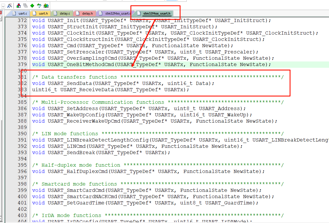
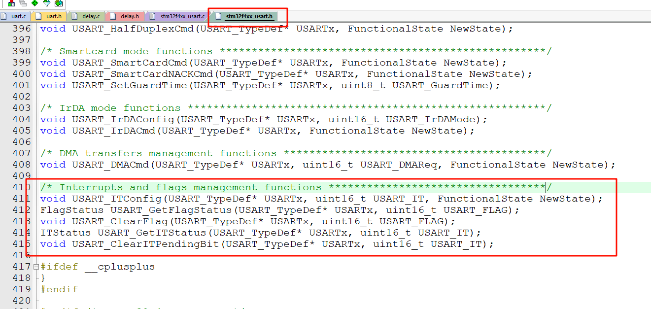
直接从,h文件能很快定位到函数,这两个就是发送与接受数据的函数。
除了这两个以外,还需要一些获取串口状态的函数,这些用于避免发送或接受数据混乱(当串口正在发送数据,而第二批需要使用串口发送数据时,不应该打断它,而是判断串口是否发送完毕后,再进行自己的发送,接受数据亦是如此)。
(1) 串口发送数据
UART1的发送数据,发送数据方向是 下位机(单片机) ->上位机(电脑)
整理得下面函数
c
void USART_SendData(USART_TypeDef* USARTx, uint16_t Data);
FlagStatus USART_GetFlagStatus(USART_TypeDef* USARTx, uint16_t USART_FLAG);
官方文档:
c
/**
  * @brief  Transmits single data through the USARTx peripheral.
  * @param  USARTx: where x can be 1, 2, 3, 4, 5, 6, 7 or 8 to select the USART or
  *         UART peripheral.
  * @param  Data: the data to transmit.
  * @retval None
  */
void USART_SendData(USART_TypeDef* USARTx, uint16_t Data)
翻译:
c
/**
  * @brief  通过指定的 USARTx 外设发送单个数据。
  * @param  USARTx: x 可以为 1、2、3、4、5、6、7 或 8,用于选择具体的 USART 或 UART 外设。
  * @param  Data: 要发送的数据。
  * @retval 无返回值
  */
作用:用于指定USART发送数据的
注意:发送数据的类型是uint16_t,是16位的,小心发生截断。
官方文档:
c
/**
  * @brief  Checks whether the specified USART flag is set or not.
  * @param  USARTx: where x can be 1, 2, 3, 4, 5, 6, 7 or 8 to select the USART or
  *         UART peripheral.
  * @param  USART_FLAG: specifies the flag to check.
  *          This parameter can be one of the following values:
  *            @arg USART_FLAG_CTS:  CTS Change flag (not available for UART4 and UART5)
  *            @arg USART_FLAG_LBD:  LIN Break detection flag
  *            @arg USART_FLAG_TXE:  Transmit data register empty flag
  *            @arg USART_FLAG_TC:   Transmission Complete flag
  *            @arg USART_FLAG_RXNE: Receive data register not empty flag
  *            @arg USART_FLAG_IDLE: Idle Line detection flag
  *            @arg USART_FLAG_ORE:  OverRun Error flag
  *            @arg USART_FLAG_NE:   Noise Error flag
  *            @arg USART_FLAG_FE:   Framing Error flag
  *            @arg USART_FLAG_PE:   Parity Error flag
  * @retval The new state of USART_FLAG (SET or RESET).
  */
FlagStatus USART_GetFlagStatus(USART_TypeDef* USARTx, uint16_t USART_FLAG)
翻译:
c
/**
  * @brief  检查指定的 USART 标志位是否被置位。
  * @param  USARTx: x 可以为 1、2、3、4、5、6、7 或 8,用于选择具体的 USART 或 UART 外设。
  * @param  USART_FLAG: 指定要检查的标志位。
  *          该参数可以是以下取值之一:
  *            @arg USART_FLAG_CTS:  CTS 变化标志(UART4 和 UART5 不支持)
  *            @arg USART_FLAG_LBD:  LIN 断点检测标志
  *            @arg USART_FLAG_TXE:  发送数据寄存器为空标志
  *            @arg USART_FLAG_TC:   发送完成标志
  *            @arg USART_FLAG_RXNE: 接收数据寄存器非空标志
  *            @arg USART_FLAG_IDLE: 空闲线路检测标志
  *            @arg USART_FLAG_ORE:  溢出错误标志
  *            @arg USART_FLAG_NE:   噪声错误标志
  *            @arg USART_FLAG_FE:   帧错误标志
  *            @arg USART_FLAG_PE:   奇偶校验错误标志
  * @retval 返回 USART_FLAG 的当前状态(SET:已置位 或 RESET:未置位)。
  */
FlagStatus USART_GetFlagStatus(USART_TypeDef* USARTx, uint16_t USART_FLAG)
作用:检查指定的 USART 标志位是否被置位。而这里需要选择USART_FLAG_TXE,表示发送数据完毕。
代码如下:
c
void USART1_SendStr(const char *str)
{
	while(*str != '\0')
	{
		USART_SendData(USART1,*str++);
		while(USART_GetFlagStatus(USART1, USART_FLAG_TXE) == RESET);
	}
}
解释:函数参数是需要发送的数据,数据按一个字节一个字节发送(str++),后面while如果是未完成USART_GetFlagStatus函数会返回RESET ,RESET == RESET为真就一直卡主,意味着USART_FLAG_TC 未完成置位,即数据没有发送完毕,当数据发送完毕函数返回SET为假跳出循环,继续发下一个字节,直到发送完毕*str 等于字符串结束标志符\0。
(2) 串口接收数据
UART1的接收数据中断服务函数,接受数据方向是 上位机(电脑) - > 下位机(单片机)
整理得下面函数
c
ITStatus USART_GetITStatus(USART_TypeDef* USARTx, uint16_t USART_IT)
uint16_t USART_ReceiveData(USART_TypeDef* USARTx)
void USART_ClearITPendingBit(USART_TypeDef* USARTx, uint16_t USART_IT)
官方文档:
c
/**
  * @brief  Checks whether the specified USART interrupt has occurred or not.
  * @param  USARTx: where x can be 1, 2, 3, 4, 5, 6, 7 or 8 to select the USART or
  *         UART peripheral.
  * @param  USART_IT: specifies the USART interrupt source to check.
  *          This parameter can be one of the following values:
  *            @arg USART_IT_CTS:  CTS change interrupt (not available for UART4 and UART5)
  *            @arg USART_IT_LBD:  LIN Break detection interrupt
  *            @arg USART_IT_TXE:  Transmit Data Register empty interrupt
  *            @arg USART_IT_TC:   Transmission complete interrupt
  *            @arg USART_IT_RXNE: Receive Data register not empty interrupt
  *            @arg USART_IT_IDLE: Idle line detection interrupt
  *            @arg USART_IT_ORE_RX : OverRun Error interrupt if the RXNEIE bit is set
  *            @arg USART_IT_ORE_ER : OverRun Error interrupt if the EIE bit is set
  *            @arg USART_IT_NE:   Noise Error interrupt
  *            @arg USART_IT_FE:   Framing Error interrupt
  *            @arg USART_IT_PE:   Parity Error interrupt
  * @retval The new state of USART_IT (SET or RESET).
  */
ITStatus USART_GetITStatus(USART_TypeDef* USARTx, uint16_t USART_IT)
翻译:
c
/**
  * @brief  检查指定的 USART 中断是否发生。
  * @param  USARTx: x 可以为 1、2、3、4、5、6、7 或 8,用于选择具体的 USART 或 UART 外设。
  * @param  USART_IT: 指定要检查的 USART 中断源。
  *          该参数可以是以下取值之一:
  *            @arg USART_IT_CTS:  CTS 变化中断(UART4 和 UART5 不支持)
  *            @arg USART_IT_LBD:  LIN 断点检测中断
  *            @arg USART_IT_TXE:  发送数据寄存器为空中断
  *            @arg USART_IT_TC:   发送完成中断
  *            @arg USART_IT_RXNE: 接收数据寄存器非空中断
  *            @arg USART_IT_IDLE: 空闲线路检测中断
  *            @arg USART_IT_ORE_RX : 当 RXNEIE 位置位时的溢出错误中断
  *            @arg USART_IT_ORE_ER : 当 EIE 位置位时的溢出错误中断
  *            @arg USART_IT_NE:   噪声错误中断
  *            @arg USART_IT_FE:   帧错误中断
  *            @arg USART_IT_PE:   奇偶校验错误中断
  * @retval 返回 USART_IT 的当前状态(SET:已发生 或 RESET:未发生)。
  */
ITStatus USART_GetITStatus(USART_TypeDef* USARTx, uint16_t USART_IT)
作用:检查是否有消息接受USART_IT_RXNE
官方文档:
c
/**
  * @brief  Returns the most recent received data by the USARTx peripheral.
  * @param  USARTx: where x can be 1, 2, 3, 4, 5, 6, 7 or 8 to select the USART or
  *         UART peripheral.
  * @retval The received data.
  */
uint16_t USART_ReceiveData(USART_TypeDef* USARTx)
翻译:
c
/**
  * @brief  返回指定 USARTx 外设最近接收到的数据。
  * @param  USARTx: x 可以为 1、2、3、4、5、6、7 或 8,用于选择具体的 USART 或 UART 外设。
  * @retval 返回接收到的数据。
  */
uint16_t USART_ReceiveData(USART_TypeDef* USARTx)
作用:接收数据
官方文档:
c
/**
  * @brief  Clears the USARTx's interrupt pending bits.
  * @param  USARTx: where x can be 1, 2, 3, 4, 5, 6, 7 or 8 to select the USART or
  *         UART peripheral.
  * @param  USART_IT: specifies the interrupt pending bit to clear.
  *          This parameter can be one of the following values:
  *            @arg USART_IT_CTS:  CTS change interrupt (not available for UART4 and UART5)
  *            @arg USART_IT_LBD:  LIN Break detection interrupt
  *            @arg USART_IT_TC:   Transmission complete interrupt.
  *            @arg USART_IT_RXNE: Receive Data register not empty interrupt.
  *
  * @note   PE (Parity error), FE (Framing error), NE (Noise error), ORE (OverRun
  *          error) and IDLE (Idle line detected) pending bits are cleared by
  *          software sequence: a read operation to USART_SR register
  *          (USART_GetITStatus()) followed by a read operation to USART_DR register
  *          (USART_ReceiveData()).
  * @note   RXNE pending bit can be also cleared by a read to the USART_DR register
  *          (USART_ReceiveData()).
  * @note   TC pending bit can be also cleared by software sequence: a read
  *          operation to USART_SR register (USART_GetITStatus()) followed by a write
  *          operation to USART_DR register (USART_SendData()).
  * @note   TXE pending bit is cleared only by a write to the USART_DR register
  *          (USART_SendData()).
  *
  * @retval None
  */
void USART_ClearITPendingBit(USART_TypeDef* USARTx, uint16_t USART_IT)
翻译:
c
/**
  * @brief  清除指定 USARTx 的中断挂起位。
  * @param  USARTx: x 可以为 1、2、3、4、5、6、7 或 8,用于选择具体的 USART 或 UART 外设。
  * @param  USART_IT: 指定要清除的中断挂起位。
  *          该参数可以是以下取值之一:
  *            @arg USART_IT_CTS:  CTS 变化中断(UART4 和 UART5 不支持)
  *            @arg USART_IT_LBD:  LIN 断点检测中断
  *            @arg USART_IT_TC:   发送完成中断
  *            @arg USART_IT_RXNE: 接收数据寄存器非空中断
  *
  * @note   PE(奇偶校验错误)、FE(帧错误)、NE(噪声错误)、
  *          ORE(溢出错误)和 IDLE(空闲线检测)挂起位的清除方式为:
  *          先读取 USART_SR 寄存器(通过 USART_GetITStatus()),
  *          再读取 USART_DR 寄存器(通过 USART_ReceiveData())。
  * @note   RXNE 挂起位也可以通过读取 USART_DR 寄存器(USART_ReceiveData())来清除。
  * @note   TC 挂起位也可以通过以下软件顺序清除:
  *          先读取 USART_SR 寄存器(USART_GetITStatus()),
  *          再写入 USART_DR 寄存器(USART_SendData())。
  * @note   TXE 挂起位只能通过向 USART_DR 寄存器写入数据(USART_SendData())来清除。
  *
  * @retval 无返回值
  */
void USART_ClearITPendingBit(USART_TypeDef* USARTx, uint16_t USART_IT)
作用:清除接受完毕后的接受中断标志位USART_IT_RXNE
解释:串口发送数据时候,我们并没有主动清除标志位,其实是硬件自动清除、自动置位的,它也是有发送结束标志位。那为什么接受数据要手动清除呢?很简答,从实际出发,我在接受数据的时候肯定是需要手动处理数据的,硬件并不知道你是否处理完成,不可能主动清除这个标志,所以就需要程序员自己规定在处理完数据后,手动清除。
代码如下:
c
volatile int8_t u1_count = 0;
volatile int8_t u1_recvbuf[128];
volatile int8_t u1_flag = 0;

void USART1_IRQHandler(void)
{
	int8_t return_data;

	if (USART_GetITStatus(USART1, USART_IT_RXNE) == SET)
	{
		return_data = USART_ReceiveData(USART1);
		u1_recvbuf[u1_count] = return_data;

		if (return_data  == '#')
		{
			u1_count = 0;
			u1_flag = 1;
		}
		else
		{
			u1_count++;
		}

		USART_ClearITPendingBit(USART1, USART_IT_RXNE); // 清除接受数据中断标志位
	}
}
注意:
- 这个接受中断服务函数是每接收一个字符都会触发一次
- 数据接收结束标志:我这里定为'#',那为什么不定为\0呢,首先我们在发送\0(' \ ' , ' 0 ')其实是两个字符,只有在C语言中才有'\0'这样的说法,所以需要一个特定字符去作为结束标志,当然你用\0当做结束标志也可以,只是你需要存储上一次的输入记录,然后再加判断,这样就过于麻烦了。
可选:
我们在接受完数据后,并不知道数据是否真的存储起来,调试起来十分麻烦,所以可以采取回发的形式(将接受到的数据再次发送到串口显示到电脑串口助手上),让接受的数据更直观的看到。
c
void USART1_IRQHandler(void)
{
	int8_t return_data;

	if (USART_GetITStatus(USART1, USART_IT_RXNE) == SET)
	{
		return_data = USART_ReceiveData(USART1);
		u1_recvbuf[u1_count] = return_data;

		if (return_data  == '#')
		{
			u1_count = 0;
			u1_flag = 1;
		}
		else
		{
			u1_count++;
		}

		// 回发
		USART_SendData(USART1,return_data);
		while(USART_GetFlagStatus(USART1, USART_FLAG_TXE) == RESET);

		USART_ClearITPendingBit(USART1, USART_IT_RXNE); // 清除接受数据中断标志位
	}
}
只需要将串口发送数据代码复用即可。
注:以上均是学习笔记。