准备软件:
stm32cubemx
keil
vscode(可选)
一,使用软件配置阶段
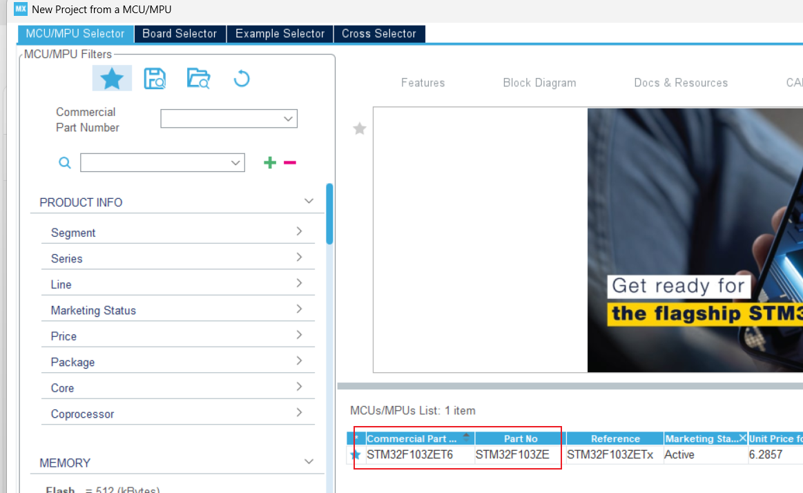
1.打开stm32cubuMx 并选择芯片 搜索对应自己mcu的芯片
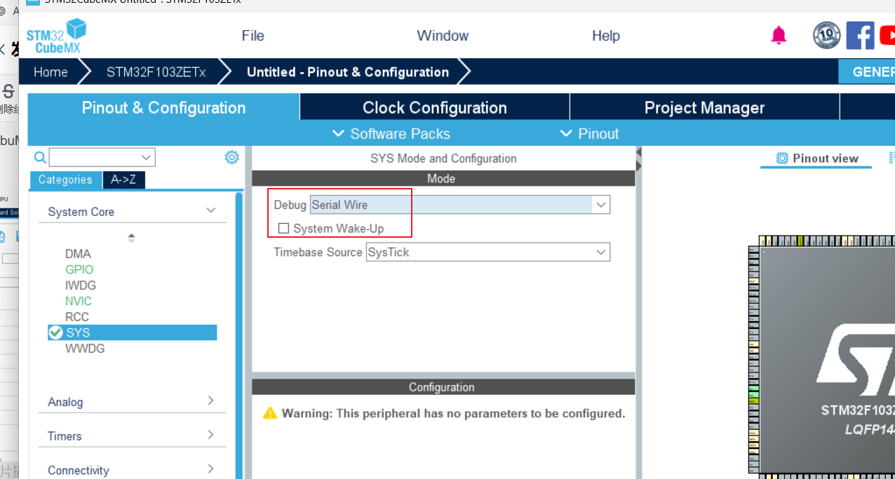
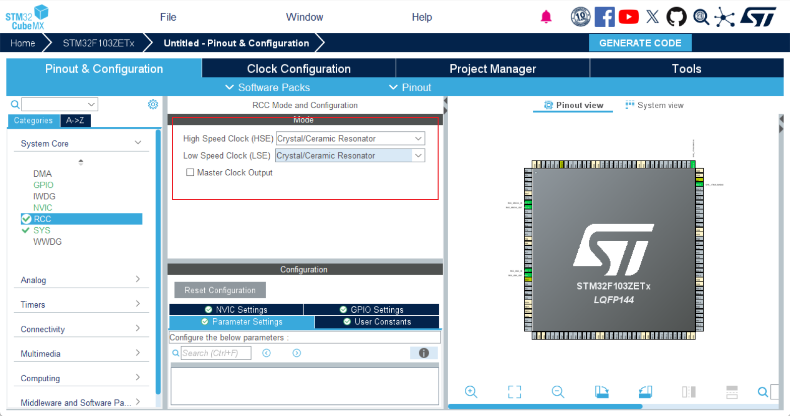
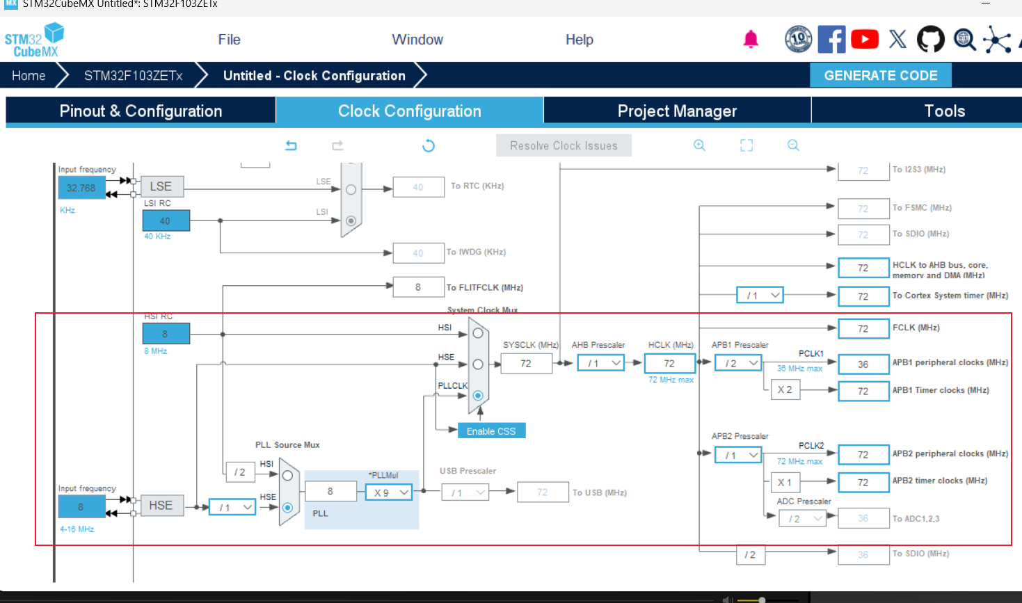
2.配置时钟 调试方式
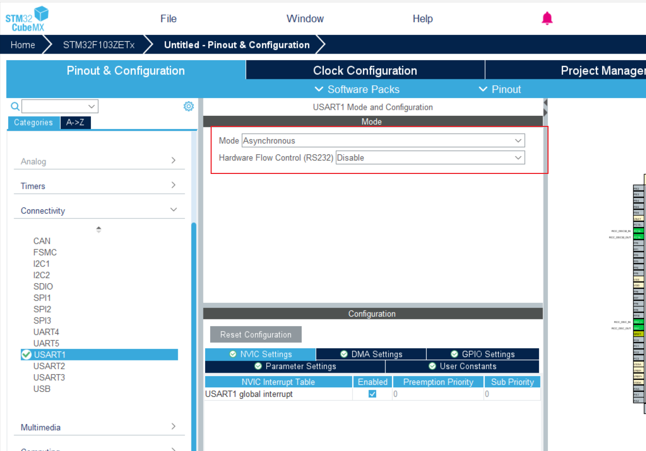
3.配置串口输出 usart1
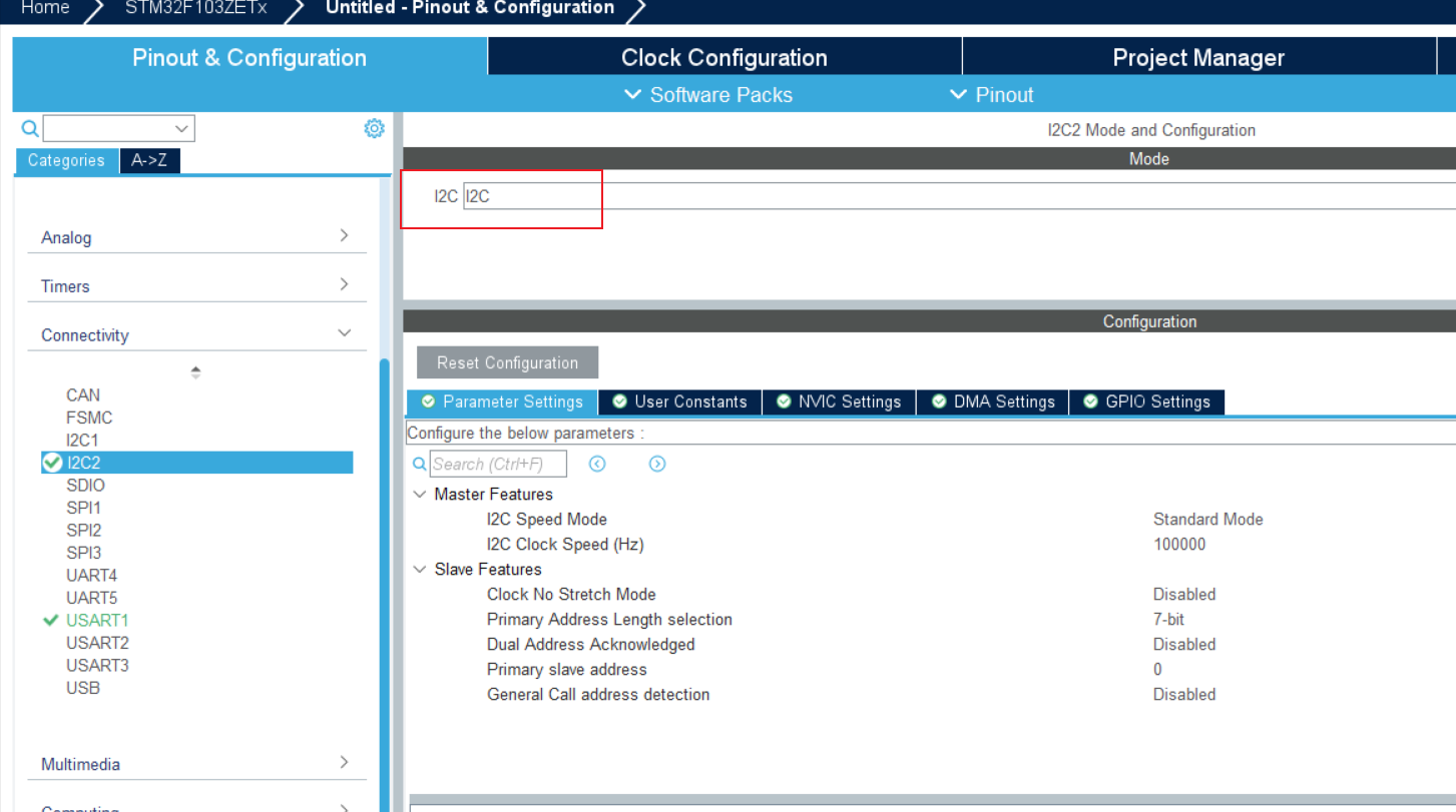
4.i2c配置
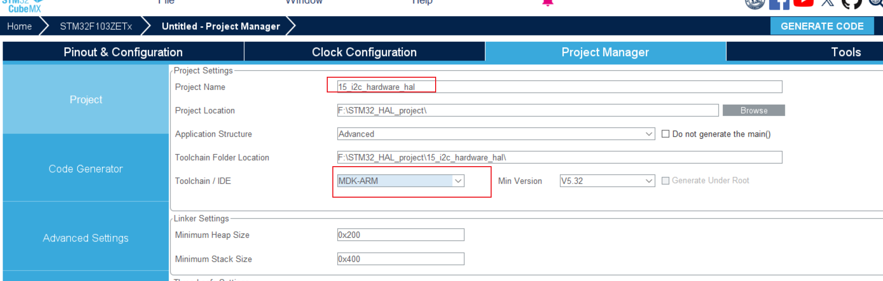
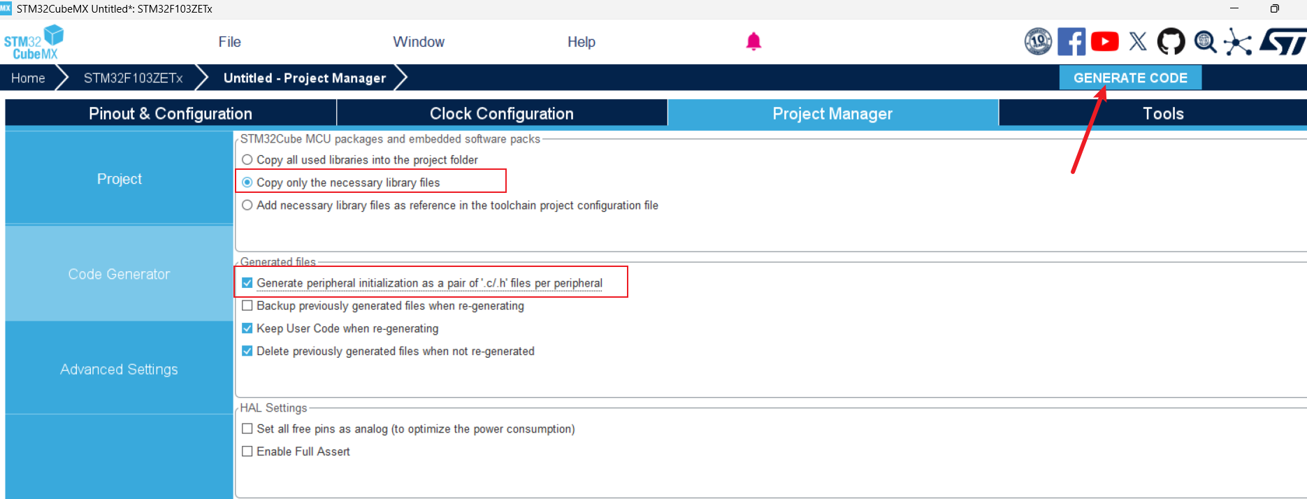
5.创建工程
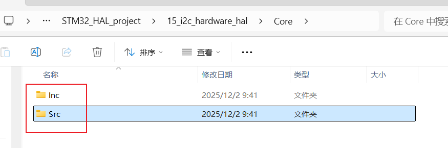
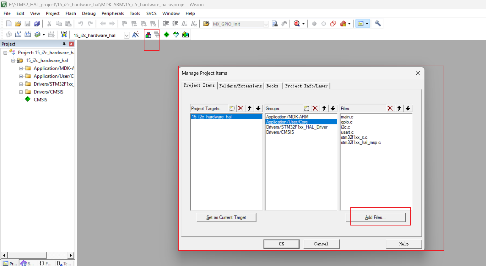
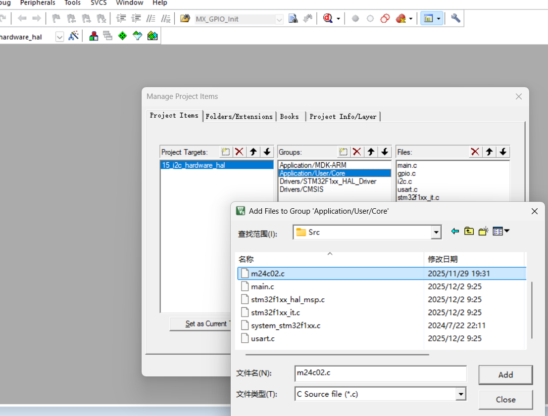
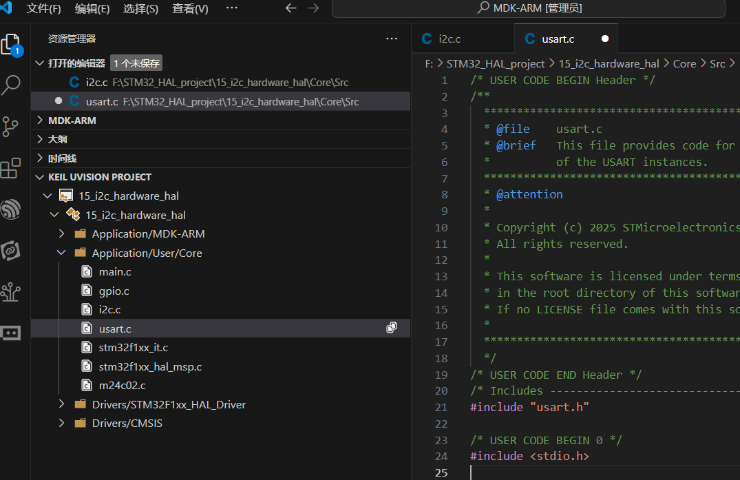
6.在新建的工程里面添加M24c.c 和.h 分别在src和inc文件夹里面
- keil打开后在添加文件
8.引入库文件
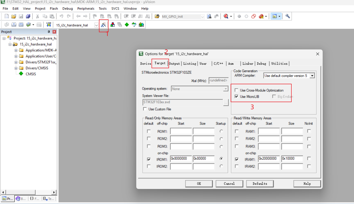
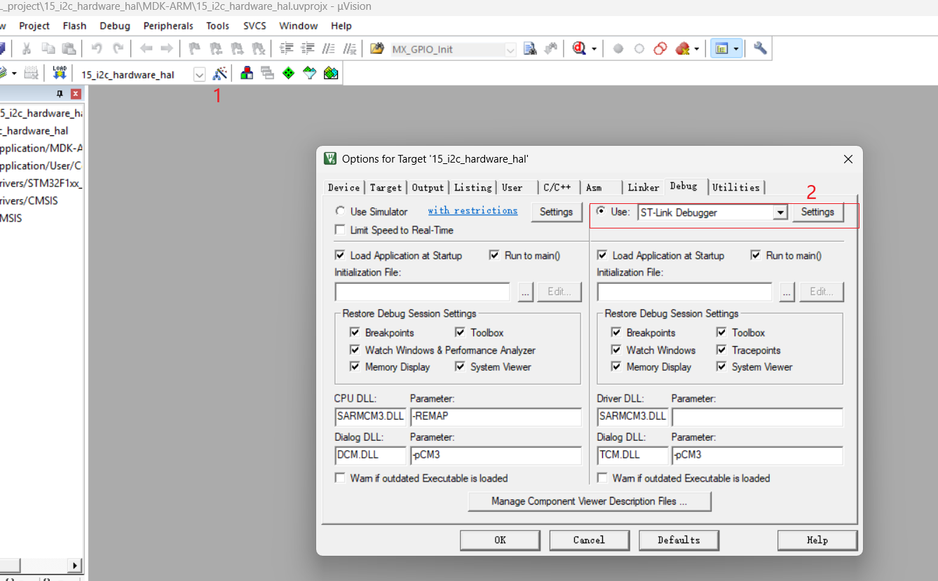
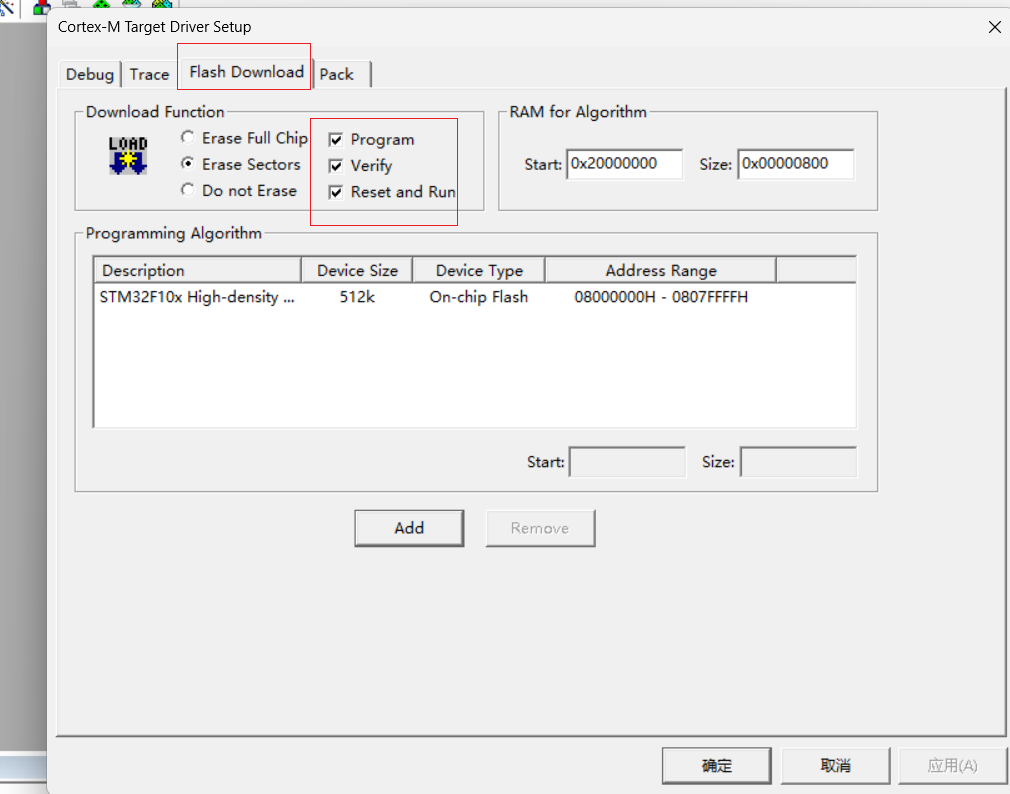
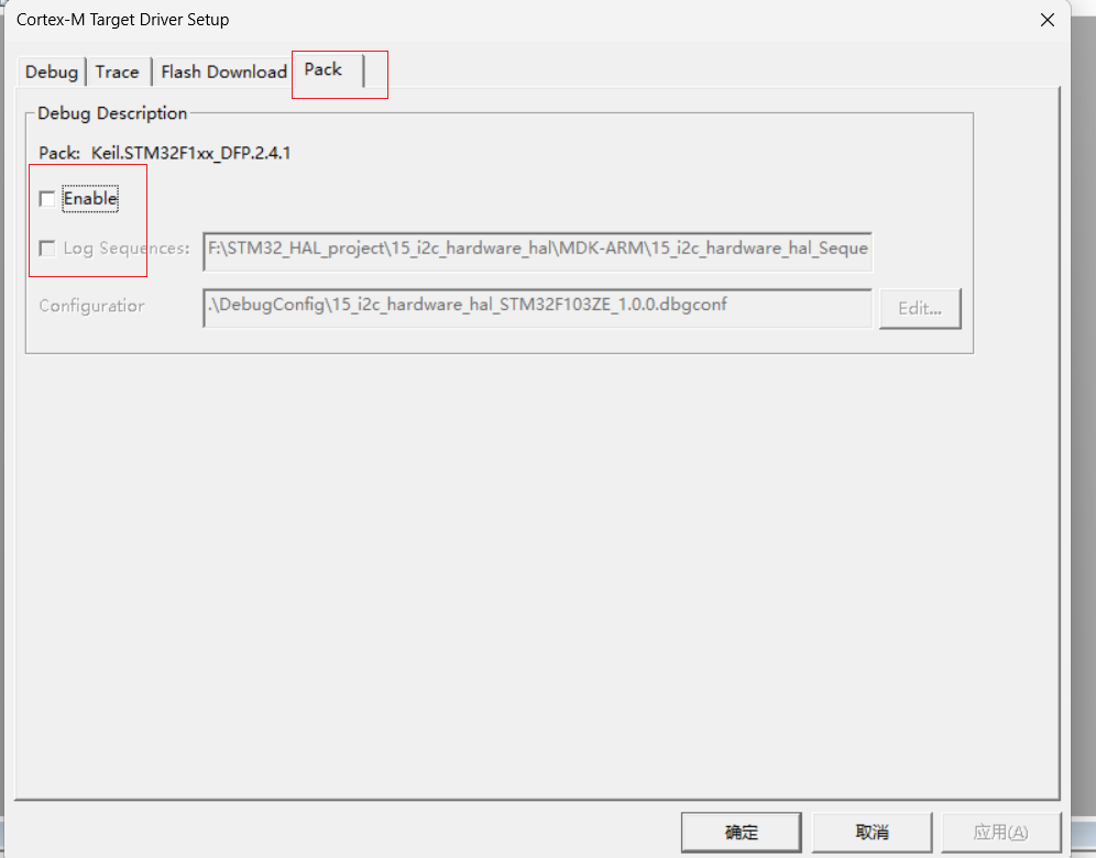
- 修改烧录后自动重启
二,代码编写阶段
使用vscode 打开编写 不喜欢的也可以使用keil编写
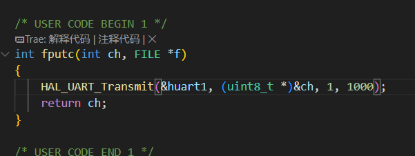
1.编写usart 重写串口输出
导入stdio.h
写fputc 来输出printf
- 编写m24c02.c 和.h
m24c02.h
c
/*
 * @Author: wushengran
 * @Date: 2024-04-29 14:44:02
 * @Description:
 *
 * Copyright (c) 2024 by atguigu, All Rights Reserved.
 */
#ifndef __M24C02_H
#define __M24C02_H

#include "i2c.h"

//宏定义读写地址
#define W_ADDR 0xA0
#define R_ADDR 0xA1

// 初始化
void M24C02_Init(void);

// 写入一个字节
void M24C02_WriteByte(uint8_t innerAddr, uint8_t byte);

// 读一个字节
uint8_t M24C02_ReadByte(uint8_t innerAddr);

// 连续写入多个字节(页写)
void M24C02_WriteBytes(uint8_t innerAddr, uint8_t * bytes, uint8_t size);

// 连续读取多个字节
void M24C02_ReadBytes(uint8_t innerAddr, uint8_t * bytes, uint8_t size);

#endif
m24c02.c
c
#include "m24c02.h"
void M24C02_Init(void)
{
MX_I2C2_Init();
}
void M24C02_WriteByte(uint8_t innerAddr, uint8_t byte)
{
HAL_I2C_Mem_Write(&hi2c2, W_ADDR, innerAddr, I2C_MEMADD_SIZE_8BIT, &byte, 1, HAL_MAX_DELAY);
HAL_Delay(5);
}
uint8_t M24C02_ReadByte(uint8_t innerAddr)
{
uint8_t data;
HAL_I2C_Mem_Read(&hi2c2, R_ADDR, innerAddr, I2C_MEMADD_SIZE_8BIT, &data, 1, HAL_MAX_DELAY);
return data;
}
void M24C02_WriteBytes(uint8_t innerAddr, uint8_t *bytes, uint8_t size)
{
HAL_I2C_Mem_Write(&hi2c2, W_ADDR, innerAddr, I2C_MEMADD_SIZE_8BIT, bytes, size, HAL_MAX_DELAY);
HAL_Delay(5);
}
void M24C02_ReadBytes(uint8_t innerAddr, uint8_t *bytes, uint8_t size)
{
HAL_I2C_Mem_Read(&hi2c2, R_ADDR, innerAddr, I2C_MEMADD_SIZE_8BIT, bytes, size, HAL_MAX_DELAY);
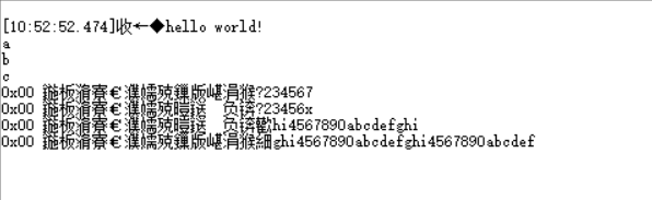
}代码验证输出
main.c
c
/* USER CODE BEGIN Header */
/**
  ******************************************************************************
  * @file           : main.c
  * @brief          : Main program body
  ******************************************************************************
  * @attention
  *
  * Copyright (c) 2025 STMicroelectronics.
  * All rights reserved.
  *
  * This software is licensed under terms that can be found in the LICENSE file
  * in the root directory of this software component.
  * If no LICENSE file comes with this software, it is provided AS-IS.
  *
  ******************************************************************************
  */
/* USER CODE END Header */
/* Includes ------------------------------------------------------------------*/
#include "main.h"
#include "i2c.h"
#include "usart.h"
#include "gpio.h"

/* Private includes ----------------------------------------------------------*/
/* USER CODE BEGIN Includes */
#include <stdio.h>
#include <string.h>
#include "m24c02.h"

/* USER CODE END Includes */

/* Private typedef -----------------------------------------------------------*/
/* USER CODE BEGIN PTD */

/* USER CODE END PTD */

/* Private define ------------------------------------------------------------*/
/* USER CODE BEGIN PD */

/* USER CODE END PD */

/* Private macro -------------------------------------------------------------*/
/* USER CODE BEGIN PM */

/* USER CODE END PM */

/* Private variables ---------------------------------------------------------*/

/* USER CODE BEGIN PV */

/* USER CODE END PV */

/* Private function prototypes -----------------------------------------------*/
void SystemClock_Config(void);
/* USER CODE BEGIN PFP */

/* USER CODE END PFP */

/* Private user code ---------------------------------------------------------*/
/* USER CODE BEGIN 0 */

/* USER CODE END 0 */

/**
  * @brief  The application entry point.
  * @retval int
  */
int main(void)
{

  /* USER CODE BEGIN 1 */


  /* USER CODE END 1 */

  /* MCU Configuration--------------------------------------------------------*/

  /* Reset of all peripherals, Initializes the Flash interface and the Systick. */
  HAL_Init();

  /* USER CODE BEGIN Init */

  /* USER CODE END Init */

  /* Configure the system clock */
  SystemClock_Config();

  /* USER CODE BEGIN SysInit */

  /* USER CODE END SysInit */

  /* Initialize all configured peripherals */
  MX_GPIO_Init();
  MX_I2C2_Init();
  MX_USART1_UART_Init();
  /* USER CODE BEGIN 2 */

  printf("hello world!\n");

  // 2. 从0地址开始,依次写入单个字符
	M24C02_WriteByte(0x00, 'a');
	M24C02_WriteByte(0x01, 'b');
	M24C02_WriteByte(0x02, 'c');

	// 3. 读取EEPROM中的数据
	printf("%c\n", M24C02_ReadByte(0x00));
	printf("%c\n", M24C02_ReadByte(0x01));
	printf("%c\n", M24C02_ReadByte(0x02));

	// 4. 连续写入多个字符(页写)
	M24C02_WriteBytes(0x00, "123456", 6);

	// printf("%c\n", M24C02_ReadByte(0x00));
	// printf("%c\n", M24C02_ReadByte(0x01));
	// printf("%c\n", M24C02_ReadByte(0x02));

	// 5. 连续读取多个字符
	uint8_t buffer[100] = {0};
	M24C02_ReadBytes(0x00, buffer, 7);
	printf("0x00 地址开始的数据为:%s\n", buffer);

	memset(buffer, 0, sizeof(buffer));

	M24C02_WriteByte(0x06, 'x');
	M24C02_ReadBytes(0x00, buffer, 7);
	printf("0x00 地址开始的数据为:%s\n", buffer);

	memset(buffer, 0, sizeof(buffer));

	// 6. 超出一页范围的连续写入
	M24C02_WriteBytes(0x00, "1234567890abcdefghi", 19);
	M24C02_ReadBytes(0x00, buffer, 19);
	printf("0x00 地址开始的数据为:%s\n", buffer);

	M24C02_WriteBytes(0x10, "1234567890abcdefghi", 19);
	M24C02_ReadBytes(0x00, buffer, 32);
	printf("0x00 地址开始的数据为:%s\n", buffer);

  /* USER CODE END 2 */

  /* Infinite loop */
  /* USER CODE BEGIN WHILE */
  while (1)
  {
    /* USER CODE END WHILE */

    /* USER CODE BEGIN 3 */
  }
  /* USER CODE END 3 */
}

/**
  * @brief System Clock Configuration
  * @retval None
  */
void SystemClock_Config(void)
{
  RCC_OscInitTypeDef RCC_OscInitStruct = {0};
  RCC_ClkInitTypeDef RCC_ClkInitStruct = {0};

  /** Initializes the RCC Oscillators according to the specified parameters
  * in the RCC_OscInitTypeDef structure.
  */
  RCC_OscInitStruct.OscillatorType = RCC_OSCILLATORTYPE_HSE;
  RCC_OscInitStruct.HSEState = RCC_HSE_ON;
  RCC_OscInitStruct.HSEPredivValue = RCC_HSE_PREDIV_DIV1;
  RCC_OscInitStruct.HSIState = RCC_HSI_ON;
  RCC_OscInitStruct.PLL.PLLState = RCC_PLL_ON;
  RCC_OscInitStruct.PLL.PLLSource = RCC_PLLSOURCE_HSE;
  RCC_OscInitStruct.PLL.PLLMUL = RCC_PLL_MUL9;
  if (HAL_RCC_OscConfig(&RCC_OscInitStruct) != HAL_OK)
  {
    Error_Handler();
  }

  /** Initializes the CPU, AHB and APB buses clocks
  */
  RCC_ClkInitStruct.ClockType = RCC_CLOCKTYPE_HCLK|RCC_CLOCKTYPE_SYSCLK
                              |RCC_CLOCKTYPE_PCLK1|RCC_CLOCKTYPE_PCLK2;
  RCC_ClkInitStruct.SYSCLKSource = RCC_SYSCLKSOURCE_PLLCLK;
  RCC_ClkInitStruct.AHBCLKDivider = RCC_SYSCLK_DIV1;
  RCC_ClkInitStruct.APB1CLKDivider = RCC_HCLK_DIV2;
  RCC_ClkInitStruct.APB2CLKDivider = RCC_HCLK_DIV1;

  if (HAL_RCC_ClockConfig(&RCC_ClkInitStruct, FLASH_LATENCY_2) != HAL_OK)
  {
    Error_Handler();
  }
}

/* USER CODE BEGIN 4 */

/* USER CODE END 4 */

/**
  * @brief  This function is executed in case of error occurrence.
  * @retval None
  */
void Error_Handler(void)
{
  /* USER CODE BEGIN Error_Handler_Debug */
  /* User can add his own implementation to report the HAL error return state */
  __disable_irq();
  while (1)
  {
  }
  /* USER CODE END Error_Handler_Debug */
}

#ifdef  USE_FULL_ASSERT
/**
  * @brief  Reports the name of the source file and the source line number
  *         where the assert_param error has occurred.
  * @param  file: pointer to the source file name
  * @param  line: assert_param error line source number
  * @retval None
  */
void assert_failed(uint8_t *file, uint32_t line)
{
  /* USER CODE BEGIN 6 */
  /* User can add his own implementation to report the file name and line number,
     ex: printf("Wrong parameters value: file %s on line %d\r\n", file, line) */
  /* USER CODE END 6 */
}
#endif /* USE_FULL_ASSERT */
验证结果 :串口不能正常输出中午 需要额外调试串口 这里就不做修改串口助手 有兴趣小伙伴 可以自己调节一下(效果正常)