江科大的课程详细丰富,所以这里开始记录课程的内容知识点还有补充,可以更好用来复习和学习
LED闪烁1.0
我们这里想要实现的是GPIOA,pin_0实现点亮
cs
#include "stm32f10x.h"                  // Device header

int main(void)
{
    RCC_APB2PeriphClockCmd(RCC_APB2Periph_GPIOA, ENABLE); //配置RCC中的APB2开启GPIO的时钟

    GPIO_InitTypeDef GPIO_InitStructure;  //定义一个结构体
    GPIO_InitStructure.GPIO_Mode = GPIO_Mode_Out_PP; //选择模式,现在是推挽输出
    GPIO_InitStructure.GPIO_Pin = GPIO_Pin_0;        //选择端口引脚
    GPIO_InitStructure.GPIO_Speed = GPIO_Speed_50MHz;//选择速度
    GPIO_Init(GPIOA, &GPIO_InitStructure); //初始化GPIO的端口,其中第二个是一个结构体

    GPIO_ResetBits(GPIOA, GPIO_Pin_0); //GPIO的输出函数,作用是使PA0输出低电平

    while (1)
    {

    }
}
LED熄灭1.1
cs
#include "stm32f10x.h"                  // Device header

int main(void)
{
    RCC_APB2PeriphClockCmd(RCC_APB2Periph_GPIOA, ENABLE); //配置RCC中的APB2开启GPIO的时钟

    GPIO_InitTypeDef GPIO_InitStructure;  //定义一个结构体
    GPIO_InitStructure.GPIO_Mode = GPIO_Mode_Out_PP; //选择模式,现在是推挽输出
    GPIO_InitStructure.GPIO_Pin = GPIO_Pin_0;        //选择端口引脚
    GPIO_InitStructure.GPIO_Speed = GPIO_Speed_50MHz;//选择速度
    GPIO_Init(GPIOA, &GPIO_InitStructure); //初始化GPIO的端口,其中第二个是一个结构体

    GPIO_SetBits(GPIOA, GPIO_Pin_0); //GPIO的输出函数,作用是使PA0输出高电平

    while (1)
    {

    }
LED闪烁2.0
cs
#include "stm32f10x.h"                  // Device header

int main(void)
{
    RCC_APB2PeriphClockCmd(RCC_APB2Periph_GPIOA, ENABLE); //配置RCC中的APB2开启GPIO的时钟

    GPIO_InitTypeDef GPIO_InitStructure;  //定义一个结构体
    GPIO_InitStructure.GPIO_Mode = GPIO_Mode_Out_PP; //选择模式,现在是推挽输出
    GPIO_InitStructure.GPIO_Pin = GPIO_Pin_0;        //选择端口引脚
    GPIO_InitStructure.GPIO_Speed = GPIO_Speed_50MHz;//选择速度
    GPIO_Init(GPIOA, &GPIO_InitStructure); //初始化GPIO的端口,其中第二个是一个结构体

    GPIO_WriteBit(GPIOA, GPIO_Pin_0,Bit_RESET); //GPIO的输出函数,作用是使PA0引脚置为低电平

    while (1)
    {

    }
}
LED熄灭2.1
cs
#include "stm32f10x.h"                  // Device header

int main(void)
{
    RCC_APB2PeriphClockCmd(RCC_APB2Periph_GPIOA, ENABLE); //配置RCC中的APB2开启GPIO的时钟

    GPIO_InitTypeDef GPIO_InitStructure;  //定义一个结构体
    GPIO_InitStructure.GPIO_Mode = GPIO_Mode_Out_PP; //选择模式,现在是推挽输出
    GPIO_InitStructure.GPIO_Pin = GPIO_Pin_0;        //选择端口引脚
    GPIO_InitStructure.GPIO_Speed = GPIO_Speed_50MHz;//选择速度
    GPIO_Init(GPIOA, &GPIO_InitStructure); //初始化GPIO的端口,其中第二个是一个结构体

    GPIO_WriteBit(GPIOA, GPIO_Pin_0,Bit_SET); //GPIO的输出函数,作用是使PA0引脚置为高电平

    while (1)
    {

    }
}
演示一下真正LED闪烁的代码
cs
#include "stm32f10x.    // Device header
#inxclude"Delay.h"
int main(void)
{
    RCC_APB2PeriphClockCmd(RCC_APB2Periph_GPIOA, ENABLE); //配置RCC中的APB2开启GPIO的时钟

    GPIO_InitTypeDef GPIO_InitStructure;  //定义一个结构体
    GPIO_InitStructure.GPIO_Mode = GPIO_Mode_Out_PP; //选择模式,现在是推挽输出
    GPIO_InitStructure.GPIO_Pin = GPIO_Pin_0;        //选择端口引脚
    GPIO_InitStructure.GPIO_Speed = GPIO_Speed_50MHz;//选择速度
    GPIO_Init(GPIOA, &GPIO_InitStructure); //初始化GPIO的端口,其中第二个是一个结构体

    while (1)
    {

    GPIO_ResetBits(GPIOA, GPIO_Pin_0); //LED闪烁
    Delay_ms(500);       //延迟500毫秒
    GPIO_SetBits(GPIOA, GPIO_Pin_0);   //LED熄灭
    Delay_ms(500);       //延时500毫秒

    GPIO_WriteBit(GPIOA, GPIO_Pin_0, Bit_RESET); //同理
    Delay_ms(500);
    GPIO_WriteBit(GPIOA, GPIO_Pin_0, Bit_SET);
    Delay_ms(500);

    GPIO_WriteBit(GPIOA, GPIO_Pin_0, (BitAction)0);// 这个就是如果要加上0和1来当作高和低电平,就需要用BitAction来强转换类型
    Delay_ms(500);
    GPIO_WriteBit(GPIOA, GPIO_Pin_0, (BitAction)1);
    Delay_ms(500);
}
}
LED流水灯
硬件连接图
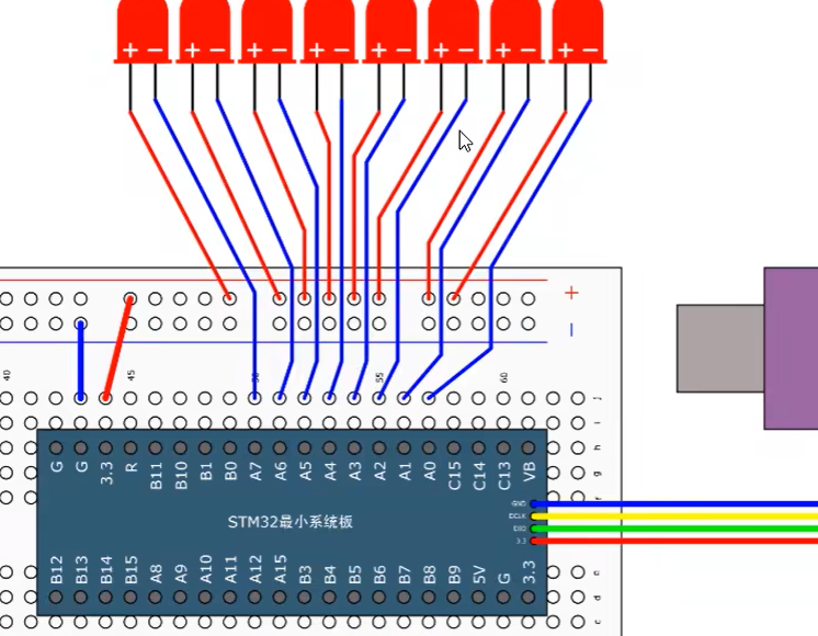
这里我们用的是GPIOA。引脚是pin_0到pin_7,一共8个引脚,我们也可以用按位或一个一个或上去但是比较麻烦,所以我们就可以用pin_All设置所以引脚为推挽输出模式,因为我们只连接了8个引脚所以高8位的引脚是闲置的没有关系
cs
#include "stm32f10x.    // Device header
#inxclude"Delay.h"
int main(void)
{
    RCC_APB2PeriphClockCmd(RCC_APB2Periph_GPIOA, ENABLE); //配置RCC中的APB2开启GPIO的时钟

    GPIO_InitTypeDef GPIO_InitStructure;  //定义一个结构体
    GPIO_InitStructure.GPIO_Mode = GPIO_Mode_Out_PP; //选择模式,现在是推挽输出
    GPIO_InitStructure.GPIO_Pin = GPIO_Pin_All;        //选择端口引脚
    GPIO_InitStructure.GPIO_Speed = GPIO_Speed_50MHz;//选择速度
    GPIO_Init(GPIOA, &GPIO_InitStructure); //初始化GPIO的端口,其中第二个是一个结构体

    while (1)
    {

GPIO_Write(GPIOA, ~0x0001); //0000 0000 0000 0001
Delay_ms(500);
GPIO_Write(GPIOA, ~0x0002); //0000 0000 0000 0010
Delay_ms(500);
GPIO_Write(GPIOA, ~0x0004); //0000 0000 0000 0100
Delay_ms(500);
GPIO_Write(GPIOA, ~0x0008); //0000 0000 0000 1000
Delay_ms(500);
GPIO_Write(GPIOA, ~0x0010); //0000 0000 0001 0000
Delay_ms(500);
GPIO_Write(GPIOA, ~0x0020); //0000 0000 0010 0000
Delay_ms(500);
GPIO_Write(GPIOA, ~0x0040); //0000 0000 0100 0000
Delay_ms(500);
GPIO_Write(GPIOA, ~0x0080); //0000 0000 1000 0000 //高8位是没有端口的,所以不用操作么而且低位才可以点亮所以要取反
Delay_ms(500);
}
}
蜂鸣器
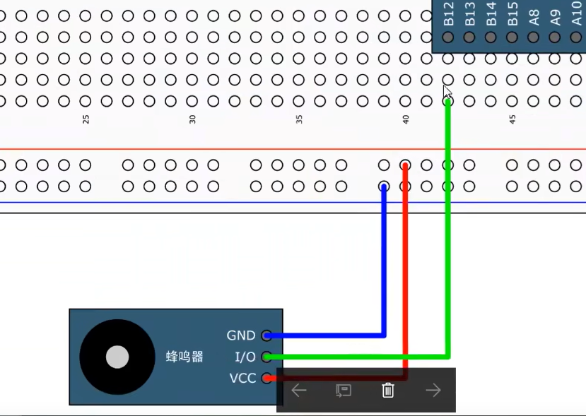
注意IO口是不能接入PA15,PB,PB4的端口的,这三个是默认的调试窗口要想变成普通端口还要进行一些配置
这里是接入到GPIOB上面,并且是pin_12上面的
cs
#include "stm32f10x.    // Device header
#inxclude"Delay.h"
int main(void)
{
    RCC_APB2PeriphClockCmd(RCC_APB2Periph_GPIOB, ENABLE); //配置RCC中的APB2开启GPIO的时钟

    GPIO_InitTypeDef GPIO_InitStructure;  //定义一个结构体
    GPIO_InitStructure.GPIO_Mode = GPIO_Mode_Out_PP; //选择模式,现在是推挽输出
    GPIO_InitStructure.GPIO_Pin = GPIO_Pin_Pin_12;        //选择端口引脚
    GPIO_InitStructure.GPIO_Speed = GPIO_Speed_50MHz;//选择速度
    GPIO_Init(GPIOB, &GPIO_InitStructure); //初始化GPIO的端口,其中第二个是一个结构体

    while (1)
    {
GPIO_ResetBits(GPIOB, GPIO_Pin_12); //蜂鸣器响
Delay_ms(500);
GPIO_SetBits(GPIOB, GPIO_Pin_12);   //不响
Delay_ms(500);

}
}