Renesas RH850-U2A中断系统介绍
- [1 RH850-U2A中断/异常/复位向量表](#1 RH850-U2A中断/异常/复位向量表)
-
- [1.1 RH850-U2A中断/异常/复位向量表寄存器](#1.1 RH850-U2A中断/异常/复位向量表寄存器)
-
- [1.1.1 复位/异常/中断系统寄存器列表](#1.1.1 复位/异常/中断系统寄存器列表)
- [1.1.2 复位/异常/中断系统寄存器介绍](#1.1.2 复位/异常/中断系统寄存器介绍)
-
- [1.1.2.1 RBASE --- Reset Vector Base Address](#1.1.2.1 RBASE — Reset Vector Base Address)
- [1.1.2.2 EBASE --- Exception Handler Vector Address](#1.1.2.2 EBASE — Exception Handler Vector Address)
- [1.1.2.3 INTBP --- Base Address of the Interrupt Handler Address Table](#1.1.2.3 INTBP — Base Address of the Interrupt Handler Address Table)
- [1.1.3 复位/异常/中断系统寄存器访问方式](#1.1.3 复位/异常/中断系统寄存器访问方式)
- [1.2 Exception Handler Address](#1.2 Exception Handler Address)
-
- [1.2.1 Direct Vector Method](#1.2.1 Direct Vector Method)
- [1.2.2 Table Reference Method](#1.2.2 Table Reference Method)
1 RH850-U2A中断/异常/复位向量表
1.1 RH850-U2A中断/异常/复位向量表寄存器
1.1.1 复位/异常/中断系统寄存器列表
| Register No. (regID, selID) | Symbol | Function |
|---|---|---|
| SR2, 1 | RBASE | Reset vector base address |
| SR3, 1 | EBASE | Exception handler vector address |
| SR4, 1 | INTBP | Base address of the interrupt handler "address" table |
1.1.2 复位/异常/中断系统寄存器介绍
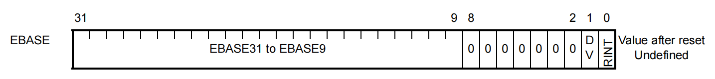
1.1.2.1 RBASE --- Reset Vector Base Address
This register indicates the reset vector address when there is a reset. If the PSW.EBV bit is 0, this register indicates the exception handler vector address and the selection method of exception handler address.

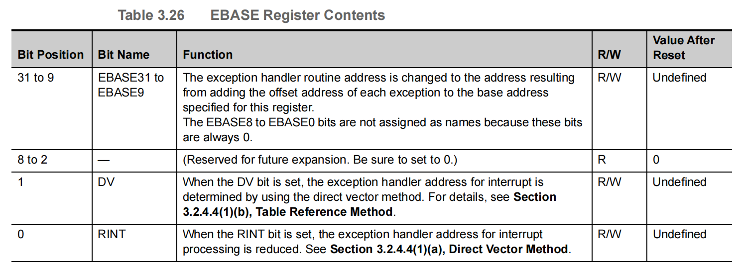
1.1.2.2 EBASE --- Exception Handler Vector Address
This register indicates the exception handler vector address and the selection method of exception handler address. This register is valid when the PSW.EBV bit is 1.
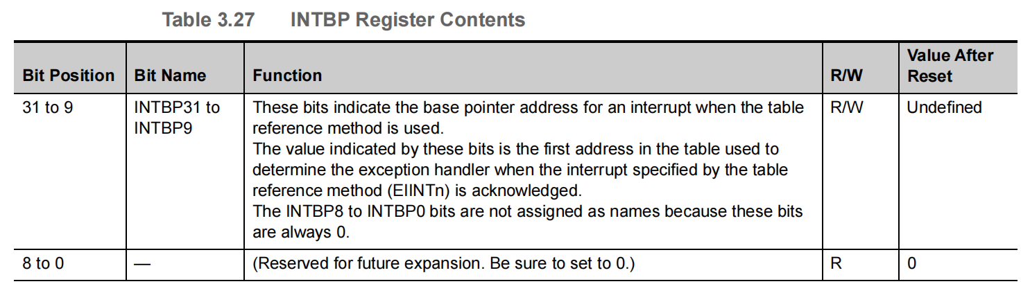
1.1.2.3 INTBP --- Base Address of the Interrupt Handler Address Table
This register indicates the base address of the table when the table reference method is selected as the interrupt handler address selection method.

1.1.3 复位/异常/中断系统寄存器访问方式
Renesas RH850-U2A的RBASE,EBASE,INTBP寄存器均为系统寄存器,其访问方式为LDSR和STSR
LDSR是在写系统寄存器的配置时使用;
STSR则是在读取当前系统寄存器的配置时使用;
1.2 Exception Handler Address
For this CPU, the exception handler address used for execution during reset input, exception acknowledgment, or interrupt acknowledgment can be changed according to the settings.
The exception handler address for resets, exceptions and interrupts is determined by using the direct vector method, in which the reference point of the exception handler address can be changed by using the PSW.EBV bit, RBASE register, and EBASE register. For user interrupts, table reference method can be also specified. If the table reference method is selected, execution can branch to the address indicated by the exception handler table allocated in the memory.
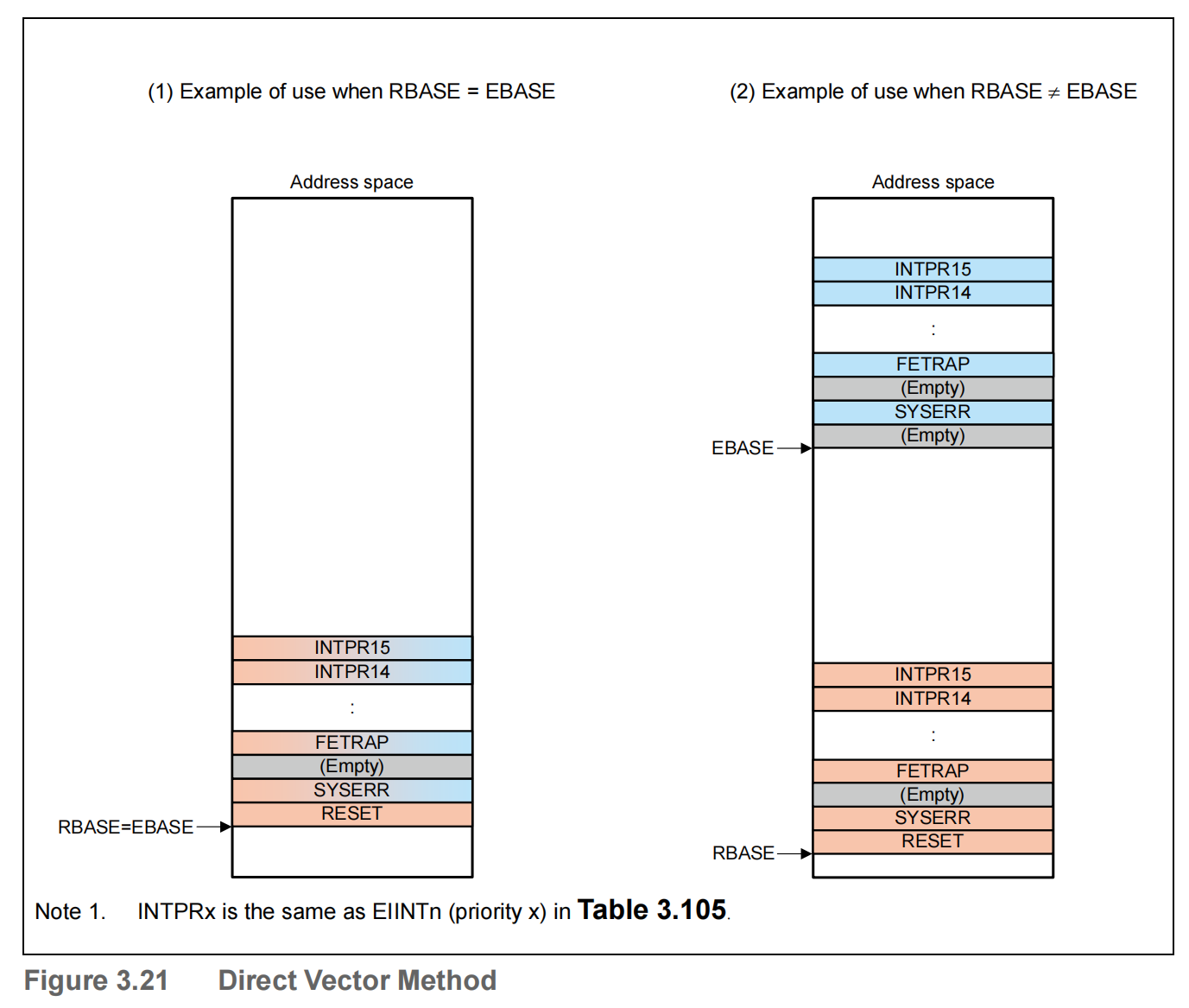
1.2.1 Direct Vector Method
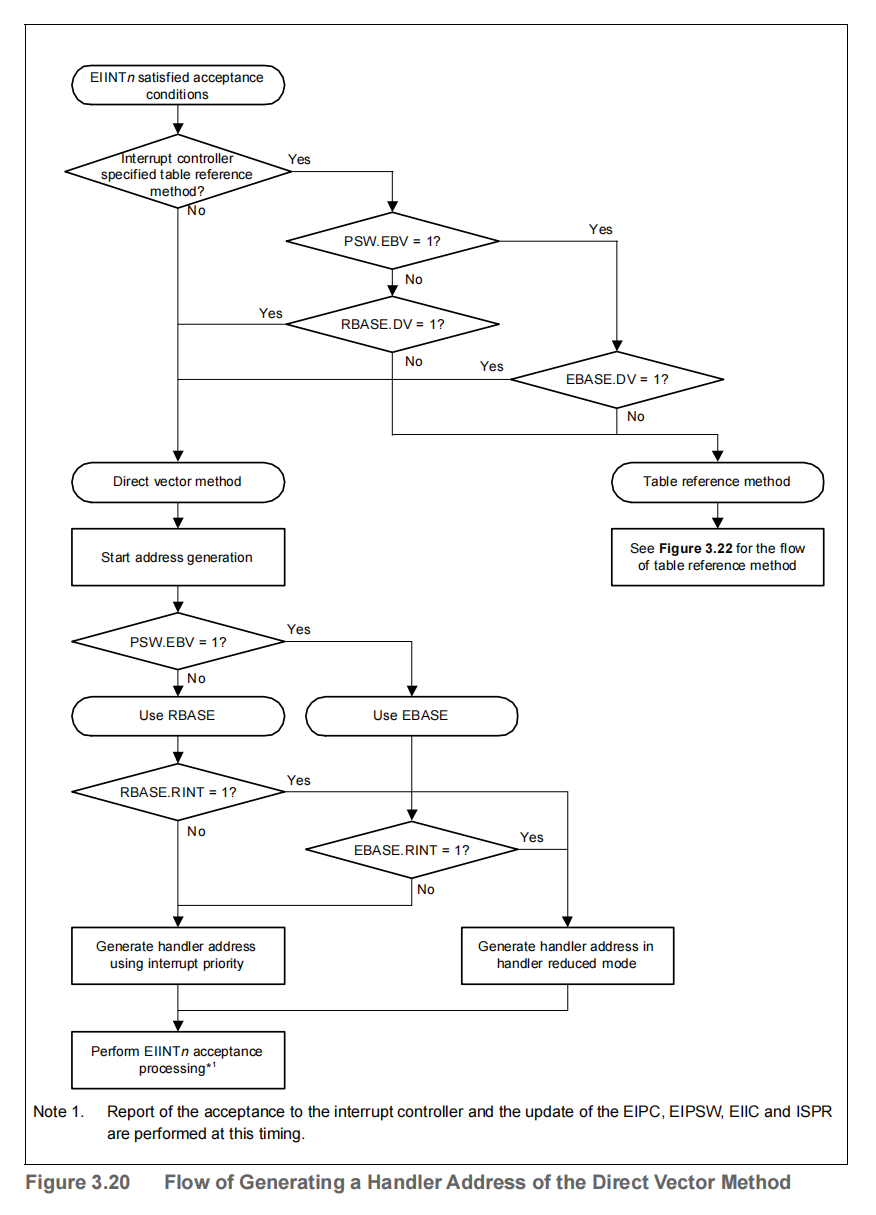
This CPU uses the result of adding the offset address shown in Table 3.105 to the base address indicated by the RBASE or EBASE register as the exception handler address.
Whether to use the RBASE or EBASE register as the base address is selected according to the PSW.EBV bit. If the PSW.EBV bit is set to 1, the EBASE register value is used as the base address. If the bit is cleared to 0, the RBASE register value is used as the base address.
However, reset input always refers to the RBASE register.
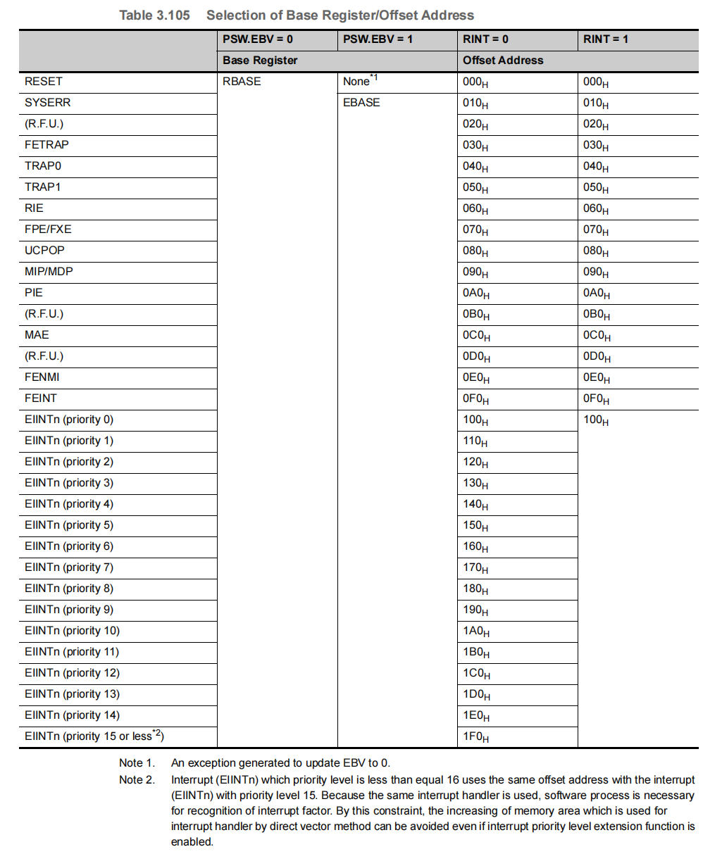
In addition, user interrupts (EIINTn) refer to the RINT bit of the selected base register, and reduce the offset address according to the value of the bit. If the RBASE.RINT bit or EBASE.RINT bit is set to 1, all user interrupts are handled using an offset address of 100H. If the bit is cleared to 0, the offset address is determined according to Table 3.105.
Figure 3.20 shows the flow of generating a handler address for the direct vector method.
The table below shows how base register is selected and offset address for each exception. The value of the PSW register used to determine the exception handler address is the value after being updated due to the acknowledgment of an exception.
The user interrupt offset address reduction function is used to reduce the memory size required by the exception handler for specific operating modes of the system. The main purpose of this is to minimize the amount of memory consumed in operating modes that use only the minimum functionality, for example, during system maintenance and diagnosis.
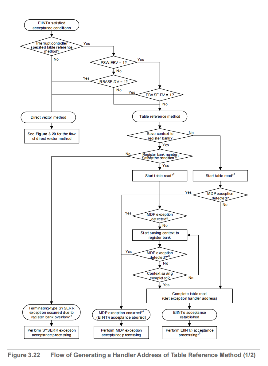
1.2.2 Table Reference Method
In the direct vector method, there is one user-interrupt exception handler for each interrupt priority, and user-interrupts with the same priority branch to the same interrupt handler, but some users might want to use code areas that differ from the start time for each interrupt handler.
This CPU defines a table reference method to accommodate to such uses.
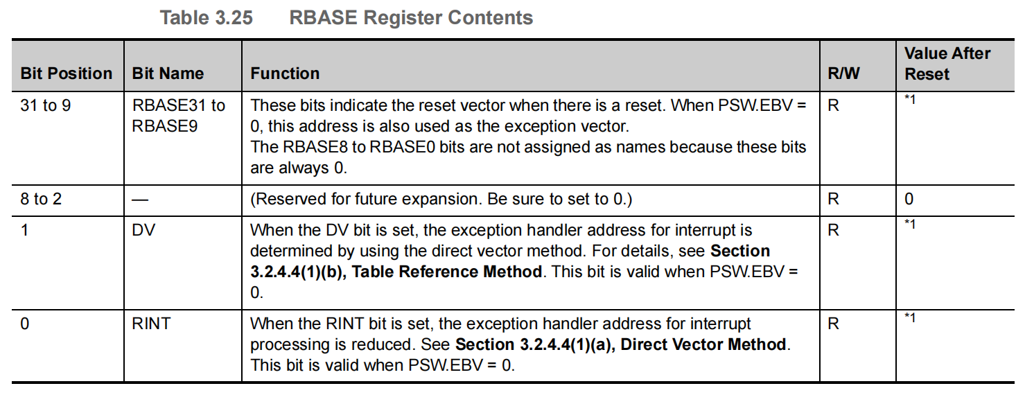
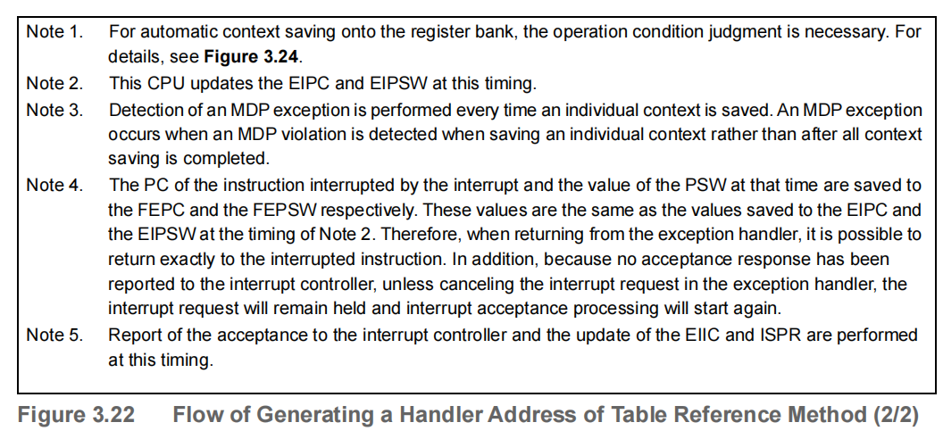
Figure 3.22 shows the flow of generating a handler address for the table reference method.
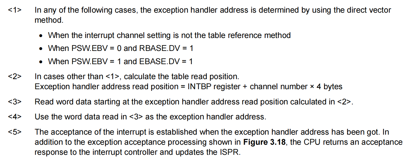
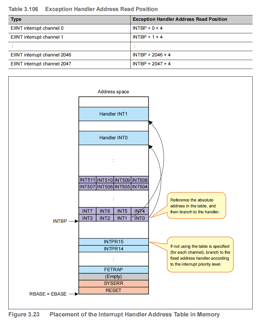
Exception handler address read positions corresponding to interrupt channels and the placement of the interrupt handler address table in memory are shown below.