降低分辨率下的校准
概述
许多高速相机可通过降低(裁剪)图像分辨率来提高采集速度。然而,在降低的分辨率下进行校准可能很困难甚至无法实现;在大多数情况下,以传感器全分辨率进行校准更为简便,且能得到更精确的结果。
降低分辨率下校准的问题
典型的高速相机可能具有1024 x 1024的分辨率。在此分辨率下,选择填满视场的标准14x10校准网格可以很好地完成校准------所有编码点和目标点都应被识别。
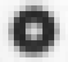
当分辨率远低于1024 x 1024时,网格上最小的点------两个编码点------将不再呈现为可识别的椭圆,而更像是这样(极度放大效果):

在这种情况下,您仍可手动选择正确的网格并继续校准。然而,当分辨率进一步降低至接近512 x 512*时,与三个定向点同心的那些小圆环也将难以被清晰解析:
此时校准将无法进行。为避免此问题,您可以在全分辨率下进行校准,然后通过简单的调整来校正裁剪造成的影响。
即使在降低的分辨率下勉强可能进行校准,使用全视场数据通常也能获得更好的结果,因为通过使用传感器边角的数据,我们可以更准确地估计畸变等参数。因此,始终建议在全分辨率下进行校准,尤其对于关键测试。
注意:对于最大分辨率有限的相机(如红外相机、超高速相机),我们也可以使用点阵更稀疏但点尺寸更大的特殊网格------例如具有超大点的8 x 6网格。这些网格可通过靶标生成器制作,或联系Correlated Solutions咨询购买成品网格。
全分辨率校准步骤
进行全分辨率校准时,请将相机设置为最大分辨率。可根据需要设置帧速和曝光时间------这些不会改变校准参数------但切勿调整光圈。如有必要,对相机进行黑电平校正;选择一个能填满传感器全视场的网格,并采集一组优质的校准图像。
之后您可以返回降低的分辨率进行测试设置------切勿移动相机或改变光圈,但允许调整照明、帧率和曝光时间。
软件操作流程与原理
我们校准的参数中有两个是"中心(X)"和"中心(Y)"。它们代表传感器针孔中心的坐标;由于实际制造差异,这些坐标通常大致位于传感器的几何中心,但绝不会完全重合。这种差异不影响精度,但必须通过校准来确定。
Vic-3D 将其表示为相对于传感器左上角的像素坐标:
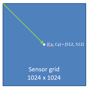
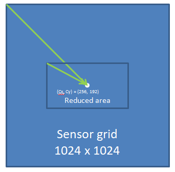
当我们降低分辨率时------以降至512 x 384为例------相机会将图像裁剪至传感器中心。(512, 512) 不再是裁剪后图像的中心------我们必须对其进行偏移补偿:
要自动计算此偏移,请在Vic-3D项目中同时添加校准图像和至少一张(降低分辨率下的)散斑图像。照常校准后,点击"文件...调整裁剪补偿"。
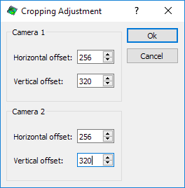
假设图像是向中心裁剪的,系统将自动填入正确的补偿值。点击"确定","中心(X)"和"中心(Y)"值将按需偏移。此操作应仅执行一次------如果重复点击,数值将被重复偏移。检查项目中的"校准"选项卡------"中心(X)"和"中心(Y)"值应大致位于您降低分辨率后图像的中心位置。
如果图像未向光学中心裁剪,则需手动输入必要的偏移值。
此校正不会以任何方式影响精度------传感器的数字特性意味着偏移量是精确可知的整数值。
注意:如果未能校正裁剪,或数值不正确,您在分析中很可能会看到极高的投影误差。此时请检查上述步骤并重试。
在此阶段保存项目,即可照常运行分析。
以下为英文原文:
Calibrating for Reduced Resolution
Overview
Many high-speed cameras allow speed increases by reducing (cropping) image resolution. However, calibration can be difficult or impossible at the reduced resolution; in most cases calibrating at the full sensor resolution is easier and will also give a more accurate result.
Problems with calibrating at reduced resolution
A typical high speed camera may have a resolution of 1024 x 1024 and at this resolution a standard 14x10 calibration grid, chosen to fill the field of view, will calibrate well - all coding and target dots should be recognized.
As the resolution decreases much below 1024 x 1024, the smallest dots on the grid - the two coding dots - will no longer be rendered as recognizable ellipses, instead looking more like this (greatly zoomed in):
In this case, you can still manually select the correct grid and proceed to calibrate. However, once the resolution starts to decrease more, towards 512 x 512*, the small circles concentric with the three orientation dots will also become poorly resolved.
In this case, calibration will be impossible. To avoid this, you can calibrate at full resolution, and then perform a simple adjustment to correct for cropping.
Even if calibration is slightly possible at reduced resolution, we can often get a better result with the full field, because we can get better estimates of parameters like distortion by using data from the corners of the sensor. Because of this, it is always recommended to calibrate at full resolution, especially for critical tests.
Note: For cameras with a limited maximum resolution (IR cameras, ultra high speed cameras) we can also use special grids with sparser but larger dots - i.e., an 8 x 6 grid with very large dots. These can be generated with the target generator or you can contact Correlated Solutions to inquire about purchasing a finished grid.
Calibrating at full resolution
For full resolution calibration, set your camera for its max resolution. Speed and exposure time can be set as necessary - these will not change the calibration parameters - but aperture must not be adjusted. Black reference the cameras, if necessary; choose a grid which fills the full field of view of the sensor, and take a good calibration set.
You can then return to the reduced resolution and set up for your test - do not move the cameras or change the aperture, but lighting, FPS, and exposure time adjustment are all allowable.
Software procedure and theory
Two of the parameters we calibrate for are Center (X) and Center (Y). These are the coordinates of the pinhole center of the sensor; they tend to be roughly in the geometric center of the sensor, but never exactly, because of real-world manufacturing variation. This variation does not harm accuracy but must be calibrated for.
Vic-3D represents this as a pixel coordinate referenced to the top left of the sensor.
When we reduce the resolution - for our example, to 512 x 384 - the camera crops the image to the center of the sensor. (512, 512) is no longer the center of this reduced image - we must offset it.
To calculate this offset automatically, add both the calibration images as well as at least one speckle image (at reduced resolution) to the project in Vic-3D. Calibrate as usual, and then click File... Adjust for cropping.
Assuming the image was cropped to the center, the correct values will be filled in. Click Ok and the Center (X) and Center (Y) values will be offset as necessary. You should do this once and only once - if you click through again, the values will be offset again. Check the Calibration tab in your project - the Center (X) and Center (Y) values should be roughly in the center of your reduced resolution image.
If the image was not cropped to the optical center, you must manually enter the necessary offset values.
This correction does not affect accuracy in any way - the digital nature of sensors means that the offset is an exact, knowable integer value.
Note *:*If you fail to correct for cropping, or the values are incorrect, you will most likely see a very high Projection Error in your analysis. In this case, check through the steps above and try again.
Save the project at this point, and run as usual.
*All numerical values in this application note are examples and will not apply to every case.