文章目录
一、简介
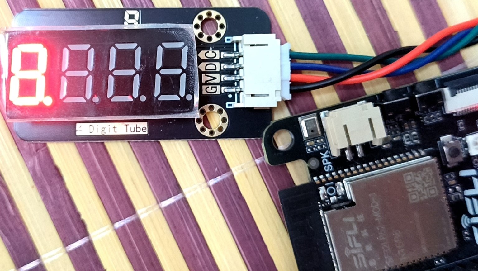
如何使用SF32LB52驱动 TM1650 I2C 数码管设备
二、SF32LB52-I2C介绍
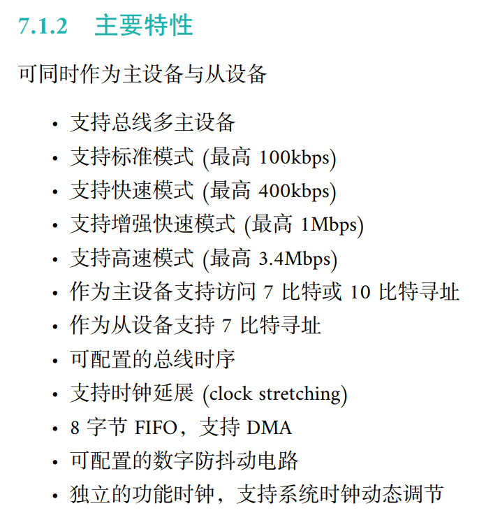
1.主要特性
SF32LB52的HPSYS有4个I2C设备,分别为I2C1~4
这里需要注意的是 硬件i2c作为主设备/从设备地址寻址为7bit寻址
7bit寻址:设备会将地址左移1位并在最后位拼接上读写标志位
如:写TM1650控制需要在0x48地址写入控制数据 7bit寻址时写入地址需要是0x24,设备左移一位后就是0x48
2.I2C结构
从下面结构图可以看出,I2C设备共有 4输入 4 输出
其中:
fclk:时钟输入信号
dma_req:DMA请求信号
dma_ack:DMA响应信号
int trigger:中断请求信号
scl_i/scl_o:i2c 时钟输入输出
sda_i/sda_o:数据输入输出
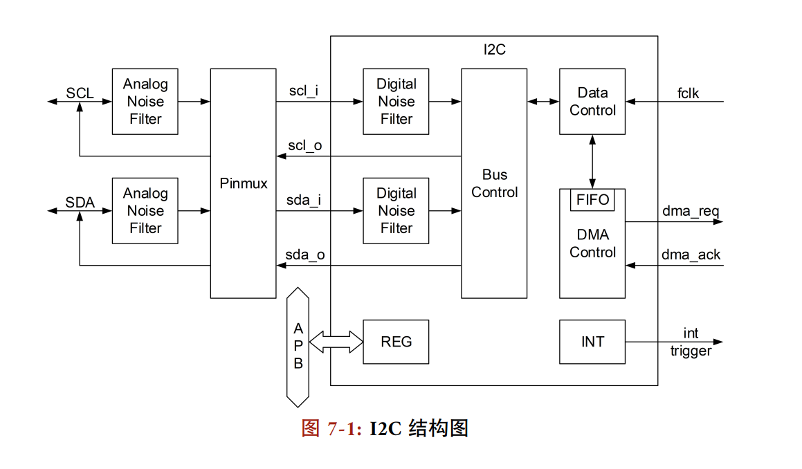
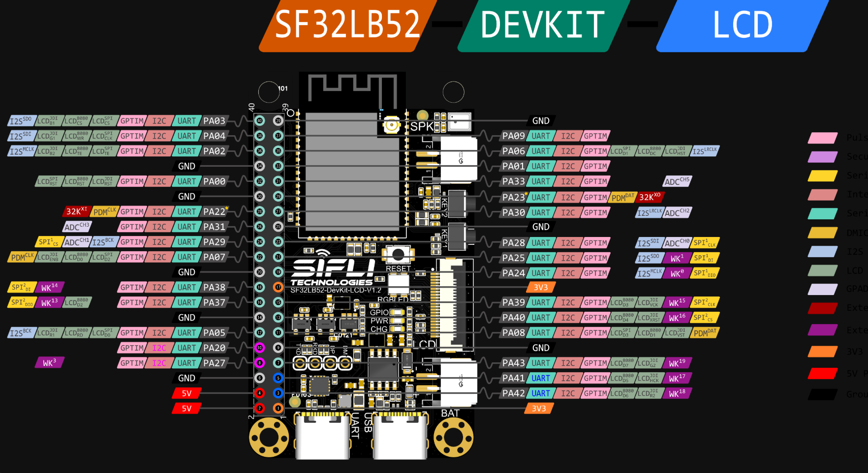
结合上面的结构图和下面的图可以发现,所有的IO口都可以配置成I2C功能
三、I2C配置流程
1.GPIO配置
需要将选择的IO口配置为I2C功能,且配置上拉模式
这里选择配置IO口为PAD_PA39和PAD_PA40,选择I2C1设备
c
	HAL_PIN_Set(PAD_PA39, I2C2_SCL, PIN_PULLUP, 1); // i2c io select
    HAL_PIN_Set(PAD_PA40, I2C2_SDA, PIN_PULLUP, 1);
2.I2C配置
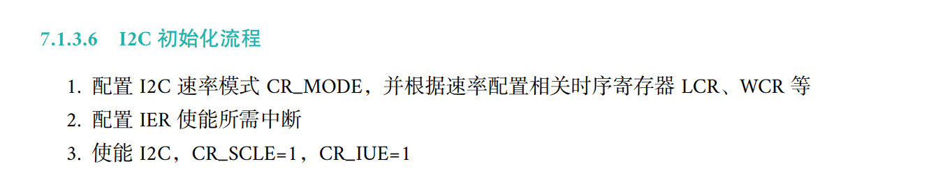
用户手册中提供了相应的初始化流程
这里i2c选择了标准模式,需要注意每个模式的最大速率值
c
/* I2C 模式选择 */
hwp_i2c1->CR &= ~0x03; hwp_i2c1->CR |= 0x00; //I2C standard mode
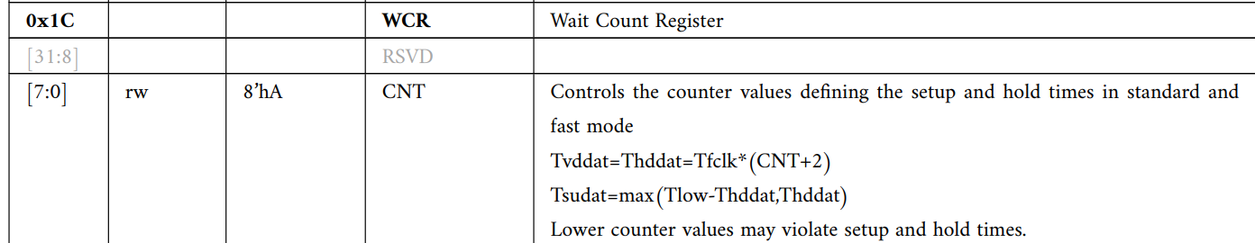
/* I2C 速率配置 */
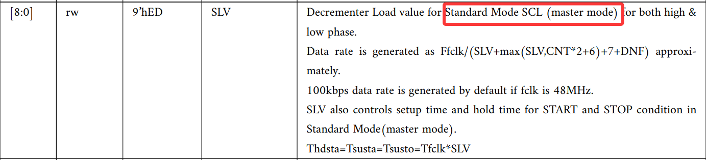
hwp_i2c1->LCR = 0xA0; //fclk = 48MHz时,默认max100KHz
hwp_i2c1->WCR = 0xA0;
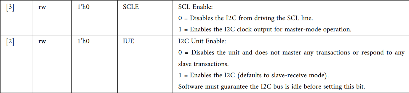
/* 配置I2C中断 */
hwp_i2c1->IER = 0x00; //关闭中断
/* 使能I2C */
hwp_i2c1->CR &= ~0x06; hwp_i2c1->CR |= 0x06; //使能I2C模式选择位
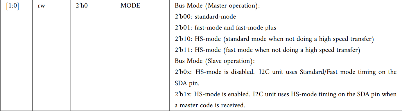
标志模式,标准模式max速率为100khz
因此根据计算公式,当fclk为48Mhz时,SLV+max(SLV,CNT*2+6)+7+DNF) 需要大于480,其中DNF为滤波数字滤波器延迟,这里没有开启数字滤波器
使能I2C使能,至此I2C初始化已经完成,后续是I2C数据发送接收流程
3.I2C收发
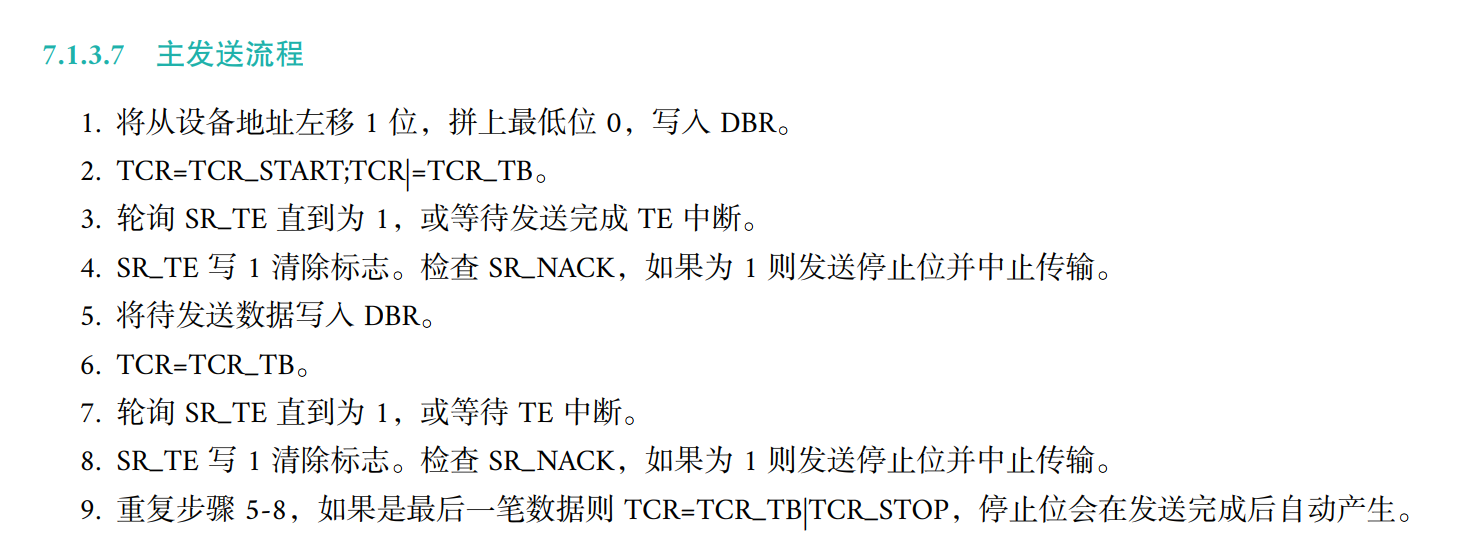
用户手册中也给出了发送接收等流程配置。
当然SF32LB52在SDK中也有相应函数的封装,使用rt_i2c_transfer函数进行数据传输
c
rt_i2c_transfer(i2c_bus, &msg1, 1);四、TM1650
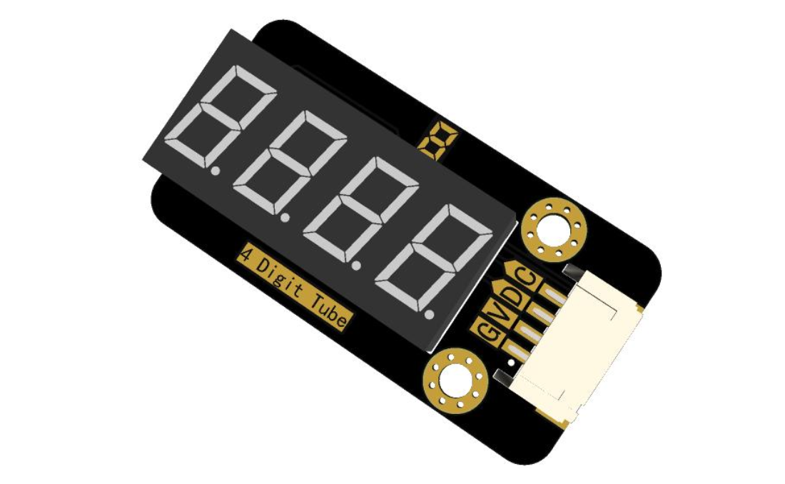
接下来说明如何i2c驱动TM1650显示数码管
对于硬件i2c驱动设备,完成配置硬件驱动后只需要给相应地址写入对应数据即可。
1.地址与数据
TM1650控制数码管显示共两个配置
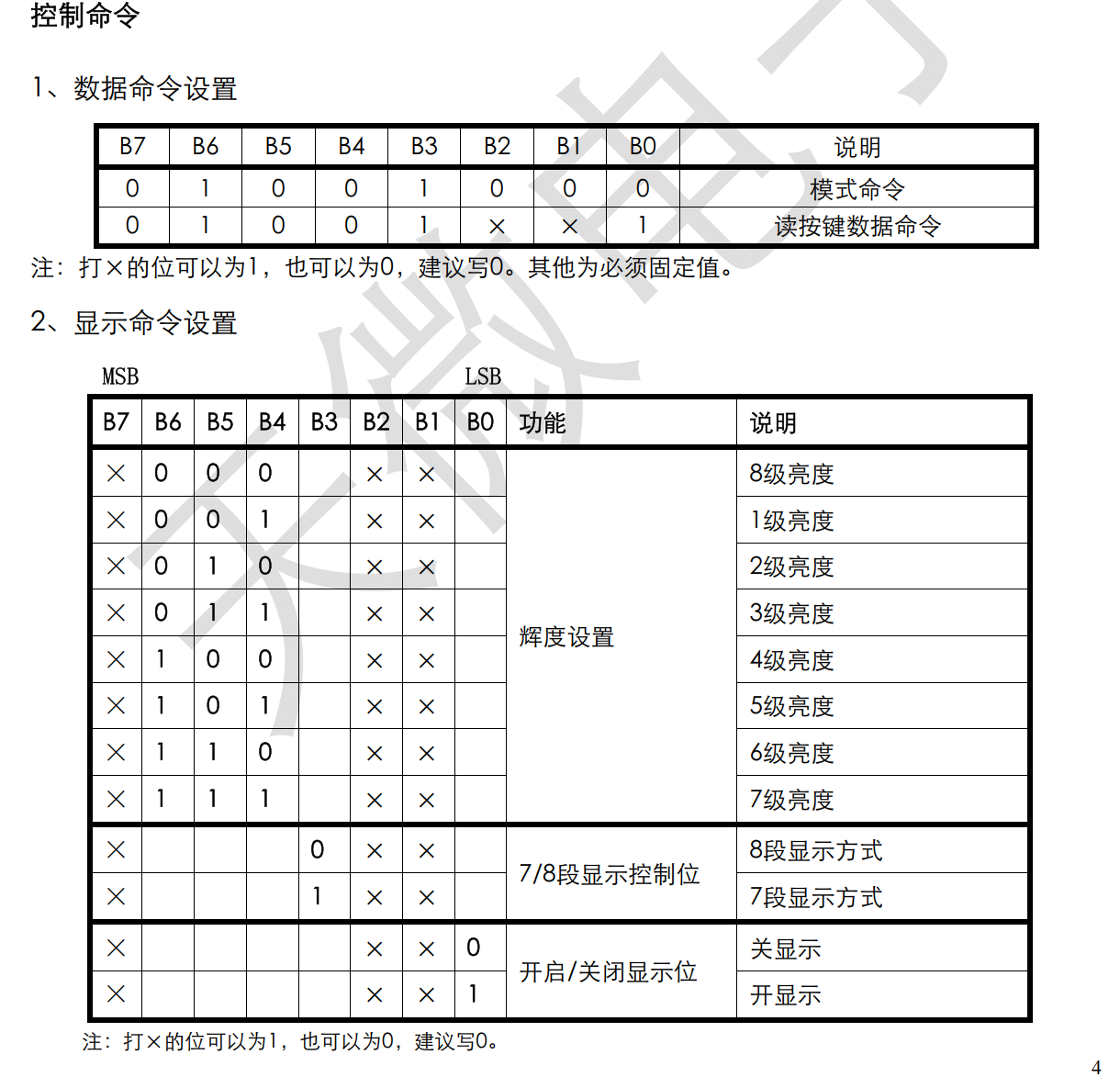
1.模式命令:地址0x48 数据:显示命令,如下图(控制显示亮度、7/8段显示、开关)
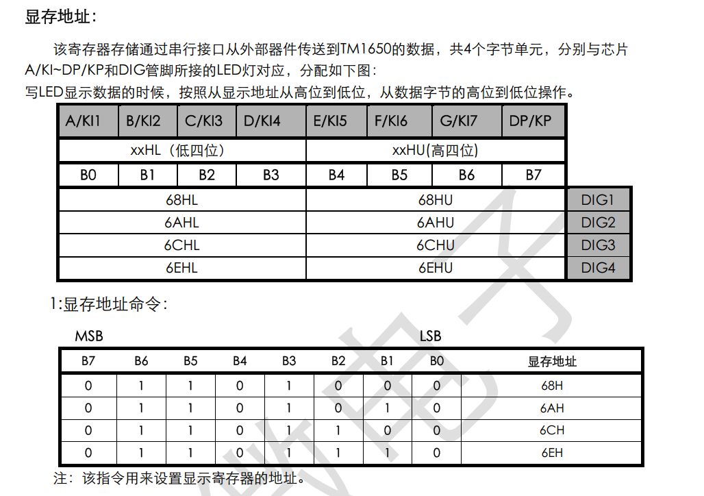
2.现存命令:地址0x68、0x6A、0x6C、0x6E 一一对应四个数码管的显示 数据:共阴极数码管显示
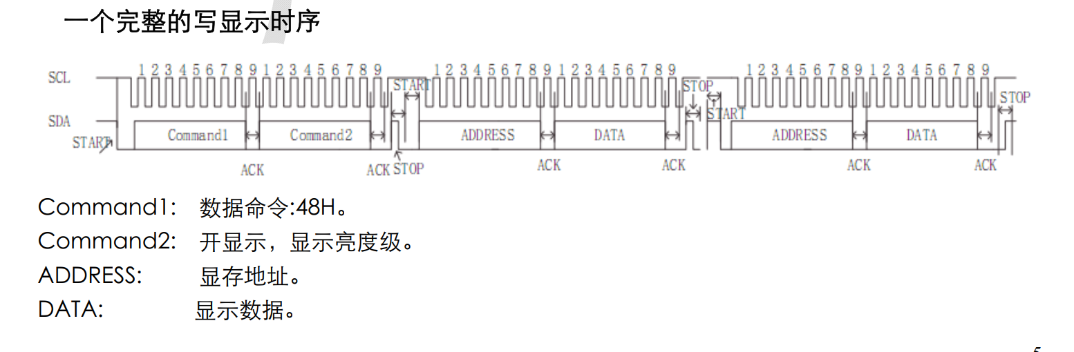
2.指令格式
指令格式如下:需要先配置亮度等控制指令,然后再配置对应数码管的显示
-> 0x48地址 ->0x414级亮度、8段显示、开启 -> 0x68第一个数码管 ->0x33显示数据 ->0x6A第二个数码管 ->0x44显示数据 ...
c
void set_brightness(uint8_t brightness)
{
    msg1.addr   = 0x24;
    msg1.flags  = RT_I2C_WR;
    msg1.len    = 1;
    msg1.buf = &brightness;
    rt_i2c_transfer(i2c_bus, &msg1, 1);
}

void set_data(uint8_t data)
{
    msg2.addr   = 0x34;
    msg2.flags  = RT_I2C_WR;
    msg2.len    = 1;
    msg2.buf = &data;
    rt_i2c_transfer(i2c_bus, &msg2, 1);
}
void main(void)
{
		...
    set_brightness(0x01);
    set_data(0x34);
    ...
}
五、示例代码
1.硬件iic
c
#include "rtthread.h"
#include "bf0_hal.h"
#include "drv_io.h"
#include "stdio.h"
#include "string.h"
#include "board.h"

#define DBG_TAG "eeprom_i2c"
#define DBG_LVL DBG_LOG
#include <rtdbg.h>

/* i2c  */

static struct rt_i2c_bus_device *i2c_bus = NULL;

/* i2c */
//Version 5.0

#define EEPROM_I2C_ADDRESS         0x50  // 7bit device address of EEPROM

/***************************************************
EEPROM interfaces
****************************************************/

uint8_t RECEIVED = 0;
uint8_t TEST_ADDR[] =
{
    0x01,
    0x02,
    0x03,
    0x04
};
uint8_t TEST_DATA[] =
{
    0x11,
    0x22,
    0x33,
    0x44
};

/**
 * @brief Initialization work before power on EEPROM and
 * @author RDA Ri'an Zeng
 * @date 2008-11-05
 * @param void
 * @return bool:if true,the operation is successful;otherwise is failed
 * @retval
 */
unsigned char EEPROM_init(void)
{

    //uint8_t slaveAddr = EEPROM_I2C_ADDRESS; // 7bit address of device
    HAL_StatusTypeDef ret;

    //1. pin mux
#ifdef SF32LB52X
    HAL_PIN_Set(PAD_PA39, I2C1_SCL, PIN_PULLUP, 1); // i2c io select
    HAL_PIN_Set(PAD_PA40, I2C1_SDA, PIN_PULLUP, 1);
#elif defined(SF32LB58X)
    HAL_PIN_Set(PAD_PB28, I2C6_SCL, PIN_PULLUP, 0); // i2c io select
    HAL_PIN_Set(PAD_PB29, I2C6_SDA, PIN_PULLUP, 0);
#endif

    // 2. i2c init
    // find i2c1
#ifdef SF32LB52X
    i2c_bus = rt_i2c_bus_device_find("i2c1");
#elif defined(SF32LB58X)
    i2c_bus = rt_i2c_bus_device_find("i2c6");
#endif

    rt_kprintf("i2c_bus:0x%x\n", i2c_bus);
    if (i2c_bus)
    {
#ifdef SF32LB52X
        rt_kprintf("Find i2c bus device I2C1\n");
#elif defined(SF32LB58X)
        rt_kprintf("Find i2c bus device I2C6\n");
#endif
        // open rt_device i2c2
        // rt_device_open((rt_device_t)i2c_bus, RT_DEVICE_FLAG_RDWR);
        // //rt_i2c_open(i2c_bus, RT_DEVICE_FLAG_RDWR);
        // struct rt_i2c_configuration configuration =
        // {
        //     .mode = 0,
        //     .addr = 0,
        //     .timeout = 500, //Waiting for timeout period (ms)
        //     .max_hz = 100000, //I2C rate (hz)
        // };
        // // config I2C parameter
        // rt_i2c_configure(i2c_bus, &configuration);
        /* I2C 模式选择 */
        hwp_i2c1->CR &= ~0x03; hwp_i2c1->CR |= 0x00;  //I2C standard mode
        /* I2C 速率配置 */
        hwp_i2c1->LCR = 0xA0;  //fclk = 48MHz时,默认100KHz
        hwp_i2c1->WCR = 0xA0;
        /* 配置I2C中断 */
        hwp_i2c1->IER = 0x00;  //关闭中断
        /* 使能I2C */
        hwp_i2c1->CR &= ~0x06; hwp_i2c1->CR |= 0x06;  //使能I2C


    }
    else
    {
#ifdef SF32LB52X
        LOG_E("Can not found i2c bus I2C2, init fail\n");
#elif defined(SF32LB58X)
        LOG_E("Can not found i2c bus I2C6, init fail\n");
#endif
        return -1;
    }
    return 0;
}

void EEPROM_write_data(uint8_t addr, uint8_t data)
{
    HAL_StatusTypeDef ret;
    ret = rt_i2c_mem_write(i2c_bus, EEPROM_I2C_ADDRESS, addr, 8, &data, 1);
    LOG_D("i2c write reg:0x%x,data:0x%x,ret:%d\n", addr, data, ret);
}

void EEPROM_read_data(uint8_t addr, uint8_t *pdata)
{
    HAL_StatusTypeDef ret;
    uint8_t buf[2];

    ret = rt_i2c_mem_read(i2c_bus, EEPROM_I2C_ADDRESS, addr, 8, pdata, 1);  // ret: return data size
    LOG_D("i2c read reg:0x%x,pdata:0x%x,ret:%d\n", addr, *pdata, ret);
}

void delayms(unsigned short int ms)
{
    HAL_Delay(ms);
}

/// @brief read and write eeprom to test
/// @param
void EEPROM_test(void)
{
    unsigned char i = 0;

    for (i = 0; i < 4; i++)
    {
        EEPROM_write_data(TEST_ADDR[i], TEST_DATA[i]);
        delayms(5); //5ms delay for AT240C8SC write time cycle
    }

    for (i = 0; i < 4; i++)
    {
        EEPROM_read_data(TEST_ADDR[i], &RECEIVED);
    }
}
#include "i2c.h"
struct rt_i2c_msg msg1;
struct rt_i2c_msg msg2;

void set_brightness(uint8_t brightness)
{
    msg1.addr   = 0x24;
    msg1.flags  = RT_I2C_WR;
    msg1.len    = 1;
    msg1.buf = &brightness;
    rt_i2c_transfer(i2c_bus, &msg1, 1);
}

void set_data(uint8_t data)
{
    msg2.addr   = 0x34;
    msg2.flags  = RT_I2C_WR;
    msg2.len    = 1;
    msg2.buf = &data;
    rt_i2c_transfer(i2c_bus, &msg2, 1);
}

void  EEPROM_example(void)
{
    EEPROM_init();
    set_brightness(0x01);
    set_data(0x34);

    //EEPROM_test();
}

uint8_t g_main_flag = 0;
/**
  * @brief  Main program
  * @param  None
  * @retval 0 if success, otherwise failure number
  */
int main(void)
{
    rt_kprintf("main!!\n");
    LOG_D("Start i2c eeprom rtt demo!\n"); // Output a start message on console using printf function
    EEPROM_example();
    LOG_D("i2c end!\n"); // Output a end message on console using printf function


    //hwp_i2c1.


    while (1)
    {
        rt_thread_mdelay(5000);
        //rt_kprintf("__main loop__\r\n");
    }

    return RT_EOK;
}
2.软件iic
c
#include "rtthread.h"
#include "bf0_hal.h"
#include "drv_io.h"
#include "stdio.h"
#include "string.h"
#include "board.h"
#include "drv_gpio.h"
#include "ulog.h"

#define DBG_TAG "TM1650"
#define DBG_LVL DBG_LOG
#include <rtdbg.h>

#define TM1650_SCL GET_PIN(1,41)
#define TM1650_SDA GET_PIN(1,42)


#define SET_SCL(x) rt_pin_write(TM1650_SCL, x)
#define SET_SDA(x) rt_pin_write(TM1650_SDA, x)


#define READ_SDA rt_pin_read(TM1650_SDA)

void I2C_Start(void)
{
    SET_SDA(1);
    SET_SCL(1);
    rt_thread_mdelay(1);
    SET_SDA(0);
    rt_thread_mdelay(1);
    SET_SCL(0);
    LOG_I("I2C Start Condition");
}

void I2C_ACK(void)
{
    uint8_t timeout = 0;
    SET_SCL(1);
    rt_thread_mdelay(1);
    SET_SCL(0);
    //rt_pin_mode(TM1650_SDA, PIN_MODE_INPUT);
    while(READ_SDA&&timeout<=100)
    {
        timeout++;
        LOG_I("I2C ACK Waiting...");
    }
    //rt_pin_mode(TM1650_SDA, PIN_MODE_OUTPUT);
    rt_thread_mdelay(1);
    SET_SCL(0);
    LOG_I("I2C ACK Received");
}

void I2C_Stop(void)
{
    SET_SDA(0);
    SET_SCL(1);
    rt_thread_mdelay(1);
    SET_SDA(1);
    rt_thread_mdelay(1);
    LOG_I("I2C Stop Condition");
}


void I2C_Send_Byte(uint8_t byte)
{
    SET_SCL(0);
    rt_thread_mdelay(1);

    for(int i=0;i<8;i++)
    {
        if(byte&0x80)
            SET_SDA(1);
        else
            SET_SDA(0);
        rt_thread_mdelay(1);
        byte <<= 1;
        SET_SCL(1);
        rt_thread_mdelay(1);
        SET_SCL(0);
        rt_thread_mdelay(1);
    }
    LOG_I("I2C Sent Byte: 0x%02X", byte);
}

void TM1650_GPIO_init(void)
{
    /* Initialize GPIO pins */
    rt_pin_mode(TM1650_SCL, PIN_MODE_OUTPUT);
    rt_pin_mode(TM1650_SDA, PIN_MODE_OUTPUT);

    /* Set initial state */
    rt_pin_write(TM1650_SCL, PIN_LOW);//
    rt_pin_write(TM1650_SDA, PIN_HIGH);//

    LOG_D("GPIO initialized for TM1650 I2C communication.");
}

void TM1650_Brightness_Set(uint8_t data)
{
    I2C_Start();
    I2C_Send_Byte(0x48);
    I2C_ACK();
    I2C_Send_Byte(data);
    I2C_ACK();
    I2C_Stop();
    LOG_D("TM1650 Displayed data 0x%02X at address 0x%02X", data, 0x24);
}


void TM1650_Display(uint8_t DIG, uint8_t data)
{
    I2C_Start();
    I2C_Send_Byte(0x68 + DIG);
    I2C_ACK();
    I2C_Send_Byte(data);
    I2C_ACK();
    I2C_Stop();
    LOG_D("TM1650 Displayed data 0x%02X at address 0x%02X", data, 0x34 + DIG);
}

/**
  * @brief  Main program
  * @param  None
  * @retval 0 if success, otherwise failure number
  */
int main(void)
{
    TM1650_GPIO_init();
    TM1650_Brightness_Set(0x09); // Set brightness to maximum
    TM1650_Display(2, 0x32); // Display full brightness on digit 0

    while (1)
    {
        rt_thread_mdelay(5000);
        //rt_kprintf("__main loop__\r\n");
    }

    return RT_EOK;
}