通过原理图确定RGB灯引脚
原理图如下:

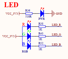
通过上面原理图可知
二级管电流方向是"三角冲过线", 也就是图中从左流到右, 电极方向相反, 所以左边是正极, 右边是负极
R, G, B三个LED灯共用一个VCC_3.3V的正极.所以,
当RGB为3.3V高电平时, 正负极电压相等, 此时无电流, LED灯灭
当RGB为0V低电平时, 正负极压差3.3V, 有电流, LED灯亮.
二极管有单向导通特性, 只有在正极电压>负极电压, 且压差在1.8V~2.2V之间时, 才能导通, 否则不导通.
所以, 配置GPIO时, 拉低灯亮, 拉高灯灭
在CubeMX中完成引脚配置
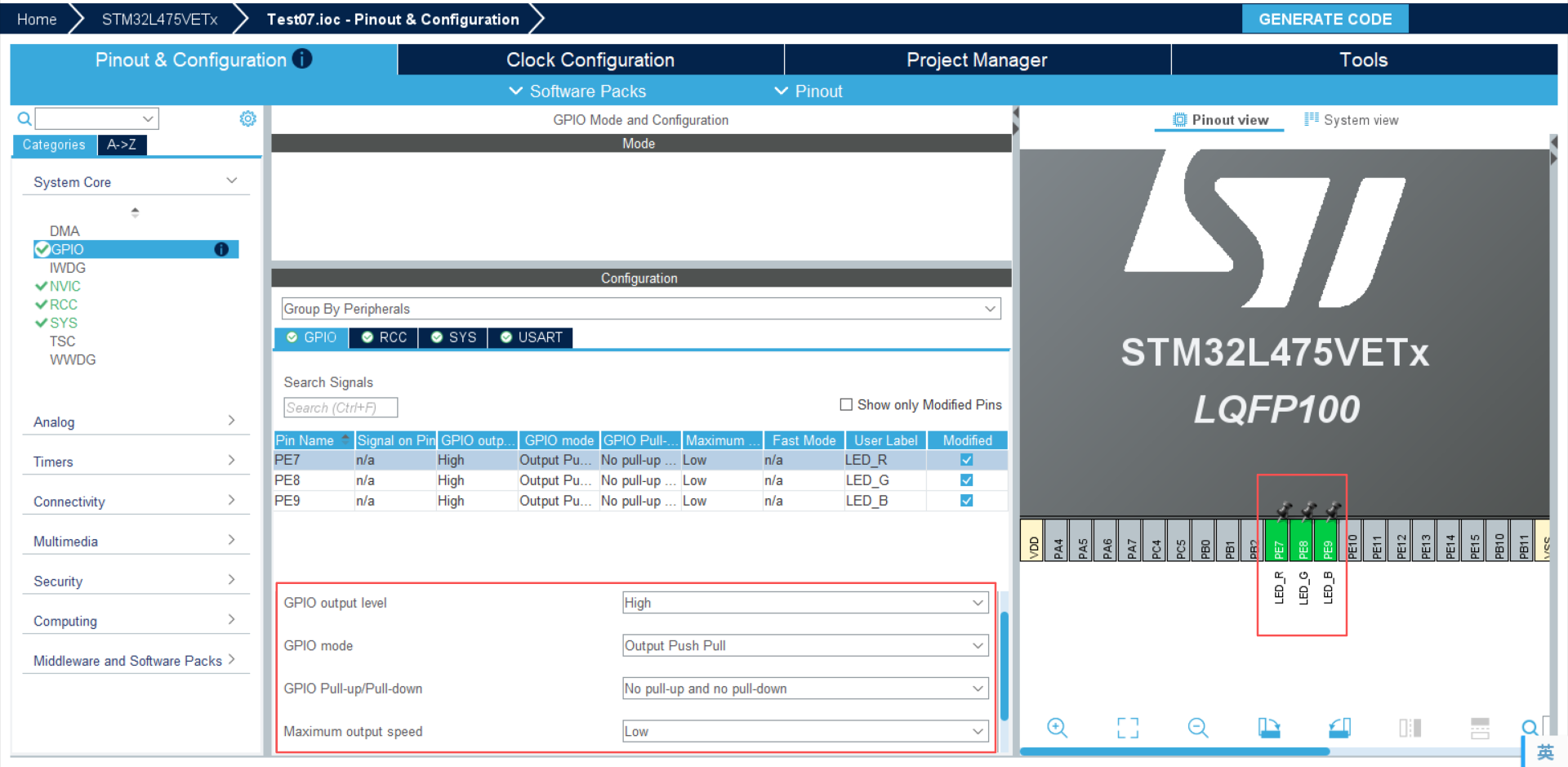
GPIO output level: GPIO默认输出电平, 高, 即默认LED等灭
GPIO mode: GPIO电平输出模式, Output Push Pull, 推挽输出, 也就是既可以输出高电平也可以输出低电平
GPIO Pull-up/Pull-down: 内部上拉电阻还是下拉电阻或者是悬空模式, 我们这里选择悬空
Maximum output speed : GPIO输出最大反转速度, 我们这里配置低速
然后PE8, PE9等都按照PE7一样的配置即可.
最后点击 GENERATE生成代码
生成的代码如下:
c
/* USER CODE BEGIN Header */
/**
  ******************************************************************************
  * @file    gpio.c
  * @brief   This file provides code for the configuration
  *          of all used GPIO pins.
  ******************************************************************************
  * @attention
  *
  * Copyright (c) 2026 STMicroelectronics.
  * All rights reserved.
  *
  * This software is licensed under terms that can be found in the LICENSE file
  * in the root directory of this software component.
  * If no LICENSE file comes with this software, it is provided AS-IS.
  *
  ******************************************************************************
  */
/* USER CODE END Header */

/* Includes ------------------------------------------------------------------*/
#include "gpio.h"

/* USER CODE BEGIN 0 */

/* USER CODE END 0 */

/*----------------------------------------------------------------------------*/
/* Configure GPIO                                                             */
/*----------------------------------------------------------------------------*/
/* USER CODE BEGIN 1 */

/* USER CODE END 1 */

/** Configure pins as
        * Analog
        * Input
        * Output
        * EVENT_OUT
        * EXTI
*/
void MX_GPIO_Init(void)
{

  GPIO_InitTypeDef GPIO_InitStruct = {0};

  /* GPIO Ports Clock Enable */
  __HAL_RCC_GPIOH_CLK_ENABLE();
  __HAL_RCC_GPIOE_CLK_ENABLE();
  __HAL_RCC_GPIOA_CLK_ENABLE();

  /*Configure GPIO pin Output Level */
  HAL_GPIO_WritePin(GPIOE, LED_R_Pin|LED_G_Pin|LED_B_Pin, GPIO_PIN_SET);

  /*Configure GPIO pins : LED_R_Pin LED_G_Pin LED_B_Pin */
  GPIO_InitStruct.Pin = LED_R_Pin|LED_G_Pin|LED_B_Pin;
  GPIO_InitStruct.Mode = GPIO_MODE_OUTPUT_PP;
  GPIO_InitStruct.Pull = GPIO_NOPULL;
  GPIO_InitStruct.Speed = GPIO_SPEED_FREQ_LOW;
  HAL_GPIO_Init(GPIOE, &GPIO_InitStruct);

}

/* USER CODE BEGIN 2 */

/* USER CODE END 2 */
可以看到是非常规范且专业的代码
- 使能GPIOE
- 设置PE7, PE8, PE9为高电平
- 配置GPIO的输出模式, 悬空, 低速
然后填上我们自己的逻辑, 我想写一个类似警灯闪烁的效果, 代码如下:
c
/* USER CODE BEGIN Header */
/**
  ******************************************************************************
  * @file           : main.c
  * @brief          : Main program body
  ******************************************************************************
  * @attention
  *
  * Copyright (c) 2026 STMicroelectronics.
  * All rights reserved.
  *
  * This software is licensed under terms that can be found in the LICENSE file
  * in the root directory of this software component.
  * If no LICENSE file comes with this software, it is provided AS-IS.
  *
  ******************************************************************************
  */
/* USER CODE END Header */
/* Includes ------------------------------------------------------------------*/
#include "main.h"
#include "usart.h"
#include "gpio.h"

/* Private includes ----------------------------------------------------------*/
/* USER CODE BEGIN Includes */
#include "trace.h"
/* USER CODE END Includes */

/* Private typedef -----------------------------------------------------------*/
/* USER CODE BEGIN PTD */

/* USER CODE END PTD */

/* Private define ------------------------------------------------------------*/
/* USER CODE BEGIN PD */

/* USER CODE END PD */

/* Private macro -------------------------------------------------------------*/
/* USER CODE BEGIN PM */

/* USER CODE END PM */

/* Private variables ---------------------------------------------------------*/

/* USER CODE BEGIN PV */

/* USER CODE END PV */

/* Private function prototypes -----------------------------------------------*/
void SystemClock_Config(void);
/* USER CODE BEGIN PFP */

/* USER CODE END PFP */

/* Private user code ---------------------------------------------------------*/
/* USER CODE BEGIN 0 */

/* USER CODE END 0 */

/**
  * @brief  The application entry point.
  * @retval int
  */
int main(void)
{

  /* USER CODE BEGIN 1 */

  /* USER CODE END 1 */

  /* MCU Configuration--------------------------------------------------------*/

  /* Reset of all peripherals, Initializes the Flash interface and the Systick. */
  HAL_Init();

  /* USER CODE BEGIN Init */

  /* USER CODE END Init */

  /* Configure the system clock */
  SystemClock_Config();

  /* USER CODE BEGIN SysInit */

  /* USER CODE END SysInit */

  /* Initialize all configured peripherals */
  MX_GPIO_Init();
  MX_USART1_UART_Init();
  /* USER CODE BEGIN 2 */

  /* USER CODE END 2 */

  /* Infinite loop */
  /* USER CODE BEGIN WHILE */

	int counter = 0;
  while (1)
  {
		counter++;
		// -- 红灯闪烁 --
		TRACE_DEBUG(" led red", counter);
		for(int i = 0; i < 3; i++) {
			HAL_GPIO_WritePin(GPIOE, GPIO_PIN_7, GPIO_PIN_RESET);
			HAL_Delay(100);
			HAL_GPIO_WritePin(GPIOE, GPIO_PIN_7, GPIO_PIN_SET);
			HAL_Delay(100);
		}

		// -- 蓝灯闪烁 --
		TRACE_DEBUG(" led blue", counter);
		for(int i = 0; i < 3; i++) {
			HAL_GPIO_WritePin(GPIOE, GPIO_PIN_9, GPIO_PIN_RESET);
			HAL_Delay(100);
			HAL_GPIO_WritePin(GPIOE, GPIO_PIN_9, GPIO_PIN_SET);
			HAL_Delay(100);
		}
    /* USER CODE END WHILE */

    /* USER CODE BEGIN 3 */
  }
  /* USER CODE END 3 */
}

/**
  * @brief System Clock Configuration
  * @retval None
  */
void SystemClock_Config(void)
{
  RCC_OscInitTypeDef RCC_OscInitStruct = {0};
  RCC_ClkInitTypeDef RCC_ClkInitStruct = {0};

  /** Configure the main internal regulator output voltage
  */
  if (HAL_PWREx_ControlVoltageScaling(PWR_REGULATOR_VOLTAGE_SCALE1) != HAL_OK)
  {
    Error_Handler();
  }

  /** Initializes the RCC Oscillators according to the specified parameters
  * in the RCC_OscInitTypeDef structure.
  */
  RCC_OscInitStruct.OscillatorType = RCC_OSCILLATORTYPE_MSI;
  RCC_OscInitStruct.MSIState = RCC_MSI_ON;
  RCC_OscInitStruct.MSICalibrationValue = 0;
  RCC_OscInitStruct.MSIClockRange = RCC_MSIRANGE_6;
  RCC_OscInitStruct.PLL.PLLState = RCC_PLL_ON;
  RCC_OscInitStruct.PLL.PLLSource = RCC_PLLSOURCE_MSI;
  RCC_OscInitStruct.PLL.PLLM = 1;
  RCC_OscInitStruct.PLL.PLLN = 40;
  RCC_OscInitStruct.PLL.PLLP = RCC_PLLP_DIV7;
  RCC_OscInitStruct.PLL.PLLQ = RCC_PLLQ_DIV2;
  RCC_OscInitStruct.PLL.PLLR = RCC_PLLR_DIV2;
  if (HAL_RCC_OscConfig(&RCC_OscInitStruct) != HAL_OK)
  {
    Error_Handler();
  }

  /** Initializes the CPU, AHB and APB buses clocks
  */
  RCC_ClkInitStruct.ClockType = RCC_CLOCKTYPE_HCLK|RCC_CLOCKTYPE_SYSCLK
                              |RCC_CLOCKTYPE_PCLK1|RCC_CLOCKTYPE_PCLK2;
  RCC_ClkInitStruct.SYSCLKSource = RCC_SYSCLKSOURCE_PLLCLK;
  RCC_ClkInitStruct.AHBCLKDivider = RCC_SYSCLK_DIV1;
  RCC_ClkInitStruct.APB1CLKDivider = RCC_HCLK_DIV1;
  RCC_ClkInitStruct.APB2CLKDivider = RCC_HCLK_DIV1;

  if (HAL_RCC_ClockConfig(&RCC_ClkInitStruct, FLASH_LATENCY_4) != HAL_OK)
  {
    Error_Handler();
  }
}

/* USER CODE BEGIN 4 */
extern UART_HandleTypeDef huart1;

void _putchar(char character)
{
  // 使用HEL库发送1字节数据
  HAL_UART_Transmit(&huart1, (uint8_t *)&character, 1, HAL_MAX_DELAY);
}
/* USER CODE END 4 */

/**
  * @brief  This function is executed in case of error occurrence.
  * @retval None
  */
void Error_Handler(void)
{
  /* USER CODE BEGIN Error_Handler_Debug */
  /* User can add his own implementation to report the HAL error return state */
  __disable_irq();
  while (1)
  {
  }
  /* USER CODE END Error_Handler_Debug */
}
#ifdef USE_FULL_ASSERT
/**
  * @brief  Reports the name of the source file and the source line number
  *         where the assert_param error has occurred.
  * @param  file: pointer to the source file name
  * @param  line: assert_param error line source number
  * @retval None
  */
void assert_failed(uint8_t *file, uint32_t line)
{
  /* USER CODE BEGIN 6 */
  /* User can add his own implementation to report the file name and line number,
     ex: printf("Wrong parameters value: file %s on line %d\r\n", file, line) */
  /* USER CODE END 6 */
}
#endif /* USE_FULL_ASSERT */
代码运行效果如下
STM32L475开发板LED实验效果