此文章我用的ai 跑的,可能会出一些小错误,我会尽量检查一下,请谅解
《企业网络架构实战(一):基于OSPF的高可用网络搭建》-思科模拟器-CSDN博客
《企业网络实战(二):NAT 实现内网 Web 服务对外发布》-CSDN博客
上面是我写的最后一部分,这些分开的是我做实验的时候一边做一边写的,比较清楚,这个看的难受可以看上面的,每一个都附带下一章节的链接
📋 全过程步骤(从零到高可用企业网络)
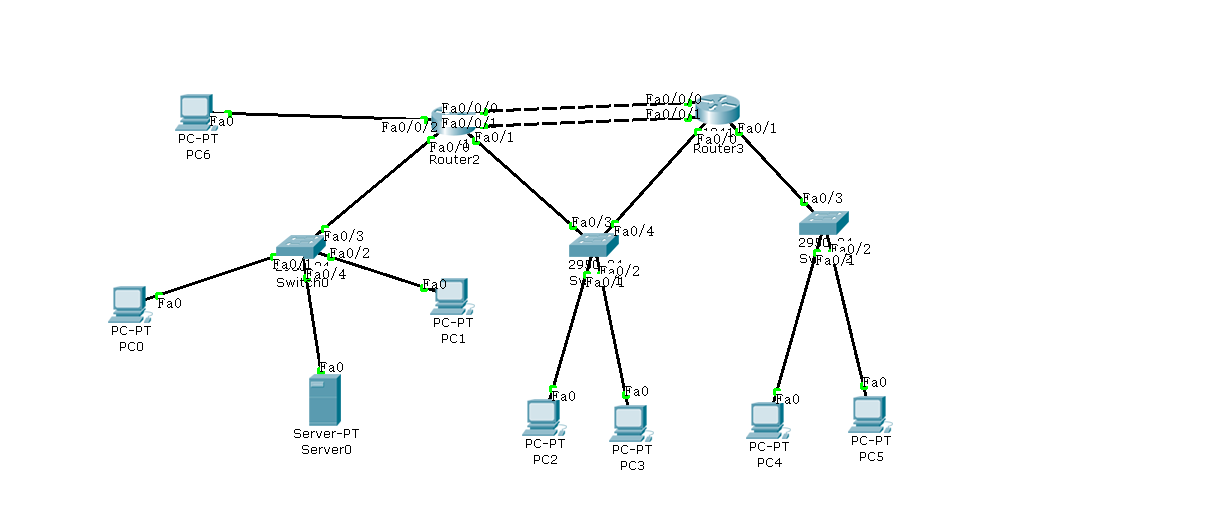
一、基础拓扑与接口配置
1. 设备与连接
-
**路由器**:两台(Router1、Router2),均添加 HWIC-4ESW 二层交换模块。
-
**交换机**:三台 2950 交换机(左、中、右)。
-
**PC**:PC0、PC1(左);PC2、PC3(中);PC4、PC5(右)。
-
**服务器**:Server0(左交换机下)。
-
**外网 PC**:连接 Router1 的扩展接口(如 Fa0/0/2)。
2. Router1 基础接口配置
```bash
enable
configure terminal
! 内网接口(连接左侧交换机)
interface fastEthernet 0/0
ip address 192.168.1.1 255.255.255.0
no shutdown
! 内网接口(连接中间交换机)
interface fastEthernet 0/1
ip address 192.168.2.1 255.255.255.0
no shutdown
! 冗余链路1:使用交换模块接口 Fa0/0/0
interface fastEthernet 0/0/0
switchport mode access
switchport access vlan 10
no shutdown
exit
interface vlan 10
ip address 192.168.10.1 255.255.255.252
no shutdown
! 冗余链路2:使用交换模块接口 Fa0/0/1
interface fastEthernet 0/0/1
switchport mode access
switchport access vlan 20
no shutdown
exit
interface vlan 20
ip address 192.168.20.1 255.255.255.252
no shutdown
! 外网接口:使用交换模块接口 Fa0/0/2,划入 VLAN 30
interface fastEthernet 0/0/2
switchport mode access
switchport access vlan 30
no shutdown
exit
interface vlan 30
ip address 203.0.113.1 255.255.255.0
no shutdown
exit
write memory
```
3. Router2 基础接口配置
```bash
enable
configure terminal
! 内网接口(连接中间交换机)
interface fastEthernet 0/0
ip address 192.168.2.2 255.255.255.0
no shutdown
! 内网接口(连接右侧交换机)
interface fastEthernet 0/1
ip address 192.168.3.1 255.255.255.0
no shutdown
! 冗余链路1:使用交换模块接口 Fa0/0/0
interface fastEthernet 0/0/0
switchport mode access
switchport access vlan 10
no shutdown
exit
interface vlan 10
ip address 192.168.10.2 255.255.255.252
no shutdown
! 冗余链路2:使用交换模块接口 Fa0/0/1
interface fastEthernet 0/0/1
switchport mode access
switchport access vlan 20
no shutdown
exit
interface vlan 20
ip address 192.168.20.2 255.255.255.252
no shutdown
exit
write memory
```
二、动态路由 OSPF 配置(替代静态路由)
1. 删除原有静态路由(如果存在)
```bash
! 在 Router1 上
no ip route 192.168.3.0 255.255.255.0 192.168.10.2
! 在 Router2 上
no ip route 192.168.1.0 255.255.255.0 192.168.10.1
```
2. 配置 OSPF
**Router1:**
```bash
router ospf 1
network 192.168.1.0 0.0.0.255 area 0
network 192.168.10.0 0.0.0.3 area 0
network 192.168.20.0 0.0.0.3 area 0
```
**Router2:**
```bash
router ospf 1
network 192.168.3.0 0.0.0.255 area 0
network 192.168.10.0 0.0.0.3 area 0
network 192.168.20.0 0.0.0.3 area 0
```
3. 验证 OSPF
```bash
show ip ospf neighbor # 应看到两个 FULL 邻居
show ip route ospf # 应看到对方网段有两条等价下一跳
```
三、NAT 配置(发布内网 Web 服务)
1. 定义内外网接口
```bash
Router1> enable
Router1# configure terminal
! 内网接口(连接左侧交换机)
interface fastEthernet 0/0
ip nat inside
! 外网接口(VLAN 30)
interface vlan 30
ip nat outside
exit
```
2. 配置静态 NAT 映射
假设 Web 服务器 IP 为 `192.168.1.10`(左侧交换机下):
```bash
ip nat inside source static tcp 192.168.1.10 80 203.0.113.1 80
```
3. 保存配置
```bash
end
write memory
```
四、Web 服务器与外网 PC 配置
1. Web 服务器(Server0)
-
连接至左侧交换机的任意空闲接口(如 Fa0/4)。
-
**IP 配置**:`192.168.1.100/24`,网关 `192.168.1.1`。
-
**开启 HTTP 服务**:在 Services 选项卡中启用 HTTP(端口 80)。
2. 外网 PC
-
连接至 Router1 的 `Fa0/0/2` 接口(已划入 VLAN 30)。
-
**IP 配置**:`203.0.113.2/24`,网关 `203.0.113.1`。
五、验证与测试
1. 基本连通性
-
从外网 PC ping `203.0.113.1`,应通。
-
从外网 PC 浏览器访问 `http://203.0.113.1`,应显示 Web 页面。
2. 查看 NAT 表项
```bash
Router1# show ip nat translations
```
应看到静态映射条目。
3. 高可用验证(冗余链路)
-
在外网 PC 上持续 ping `203.0.113.1`(或访问网页)。
-
在 Router1 上执行:
```bash
configure terminal
interface vlan10
shutdown
```
-
观察 ping 窗口:短暂超时后恢复(因为 OSPF 将流量切换至另一条链路)。
-
恢复链路:`no shutdown`,路由表重新出现两条等价路径。
六、最终网络状态
-
**动态路由**:OSPF 全网互通,两条链路负载均衡。
-
**高可用**:任意一条链路故障,业务自动切换(丢包<5个)。
-
**服务发布**:内网 Web 服务器通过 NAT 对外提供访问。
-
**扩展性**:新增网段只需在 OSPF 中宣告,无需手动指路由。