之前了解到这块芯片,是一年前的事了,当时用的还是micropython,也没觉得有什么特别的。后来芯片用多了,参数什么的也开始渐渐了解后发现这款芯片是有点意思的。双核M0+PIO+XIP最大16MB Flash,同时可以轻松超频到250MHZ,性能赶得上STM32的F4系列了,而且RAM和Flash给的很足,可玩性很高。
写这篇博客的时候我试过几种开发方式,基于Keil,基于RTT的,PlatformIO和Arduino兴趣不大就没试,因为习惯了传统嵌入式的IDE开发方式,并没有首选官方的cmake方式,从邪修开始搞起。直到写着写着到PIO部分了,因为本来对本体部分不算了解,使用第三方开发又套了一层,有点头大,索性从官方建议的开发方式重新上手。
这里使用从优信电子的YD-RP2040开发板,16MB使用优惠券就10R左右,性价比很高,相关原理图我在Github上也找到了:GitHub - initdc/YD-RP2040: An unofficial repo collecting YD-RP2040 data. · GitHub
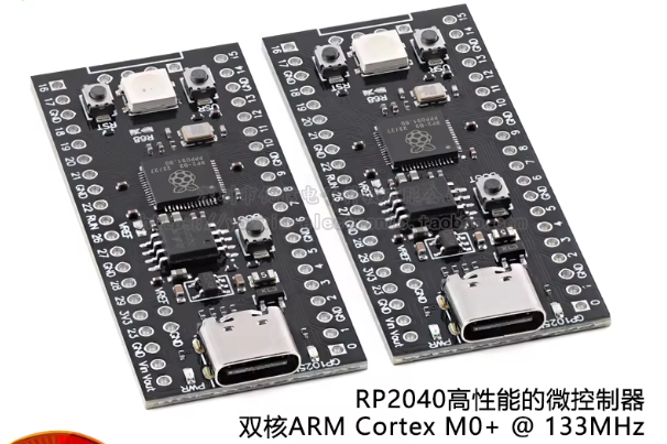
值得注意的是有两个焊盘需要手动焊接短接一下,要不没办法正常工作。
-
VREF:将微控制器的 VREF 引脚连接到 3.3V电源线。如果您不打算使用外部参考 电压,您需要将此跳线焊接闭合。
-
R68: 默认情况下,GPIO23 引脚不连接 RGB LED。为了使 LED工作时,必须焊接此跳线。
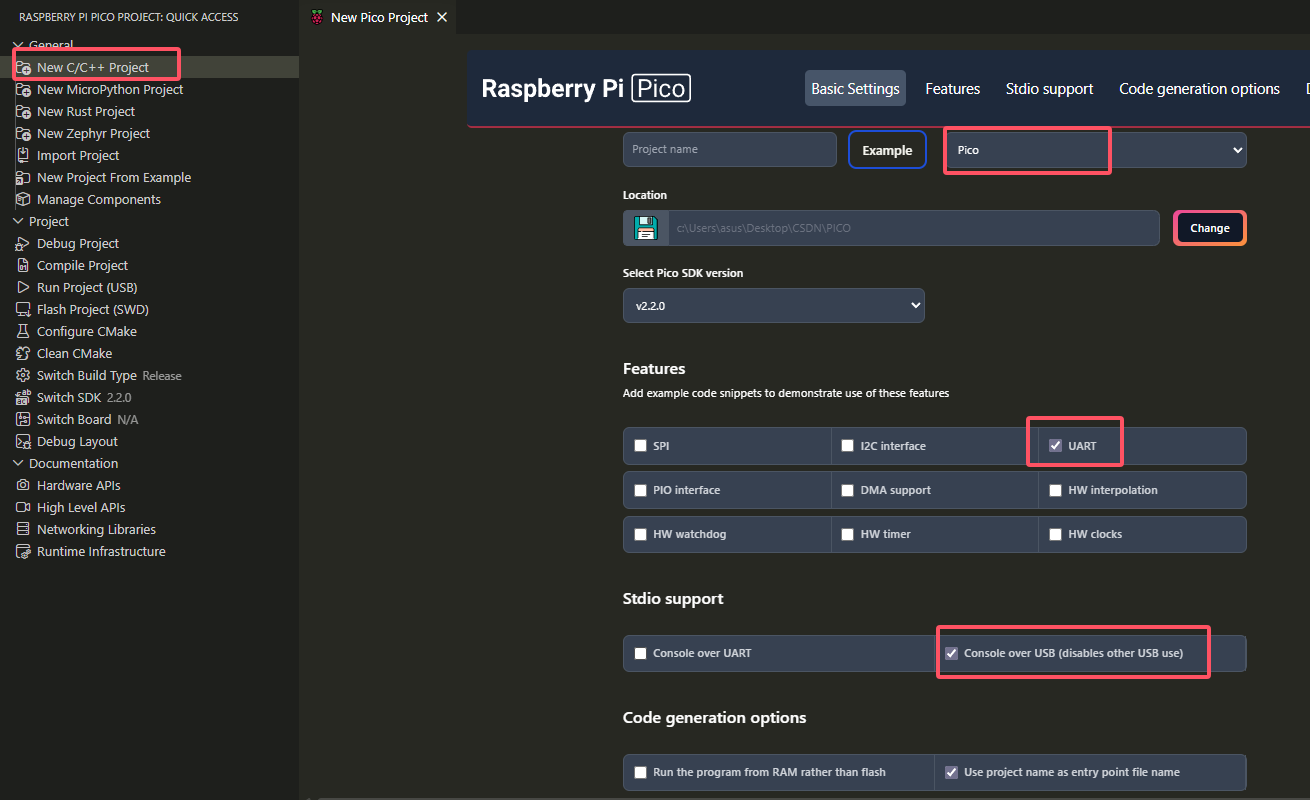
开发环境这里我使用vscode的pico插件,在2026年你也可以使用基于vscode的Trae和Qoder,因为有免费的AI辅助,这里索性先用vscode吧。使用前可能会要求下载CMake (at least version 3.13), python 3, GCC。博主很久之前就安装了,基本上安装完插件就可以使用了。
这里新建一个C工程,这里推荐勾选UART和USB,用来连接虚拟串口
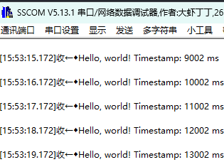
然后加入代码,找一个串口调试助手连接上,就可以显示了
cpp
#include <stdio.h>
#include "pico/stdlib.h"
#include "hardware/uart.h"
#define UART_ID uart1
#define BAUD_RATE 115200
#define UART_TX_PIN 4
#define UART_RX_PIN 5
int main()
{
stdio_init_all();
uart_init(UART_ID, BAUD_RATE);
gpio_set_function(UART_TX_PIN, GPIO_FUNC_UART);
gpio_set_function(UART_RX_PIN, GPIO_FUNC_UART);
while (true) {
uint32_t current_time = to_ms_since_boot(get_absolute_time());
printf("Hello, world! Timestamp: %d ms\n", current_time);
uart_puts(UART_ID, "Hello, UART!\n");
sleep_ms(1000);
}
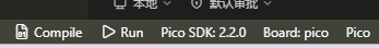
}下载程序的话是先按下BOOT,再按下RESET,再松RESET,再松BOOT,然后window显示磁盘,再在vscode上编译烧录;
实验现象:
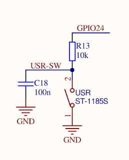
温馨提示,由于该板按键缺少 VCC 的外部上拉电阻,所以要在软件中配置内部上拉电阻使 GPIO24 正常工作。
下一步我们来点亮WS2812的灯,这个彩灯的通信原理在这里不多叙述,只需要知道它需要的时序是几百ns级别的,在RP2040上最广泛使用的是通过PIO调用。PIO跟汇编有点像,这里也不多介绍,毕竟先跑通再去学习也不迟。首先下载官方的PIO文件,放在和最外层目录。
pico-examples/pio/ws2812/ws2812.pio at master · raspberrypi/pico-examples · GitHub
然后配置CmakeLists,在原基础上进行修改:
bash
# ========== 第1步:先创建可执行文件 ==========
add_executable(260412
    260412.c
)

# ========== 第2步:生成 PIO 头文件(在 add_executable 之后)==========
pico_generate_pio_header(260412 ${CMAKE_CURRENT_LIST_DIR}/ws2812.pio)

# ========== 第3步:设置程序属性 ==========
pico_set_program_name(260412 "260412")
pico_set_program_version(260412 "0.1")

pico_enable_stdio_uart(260412 0)
pico_enable_stdio_usb(260412 1)

# ========== 第4步:链接库(添加 hardware_pio)==========
target_link_libraries(260412
    pico_stdlib
    hardware_pio        # 加入PIO 硬件支持
)
然后修改主程序,用上之前的按键:
cpp
#include <stdio.h>
#include "pico/stdlib.h"
#include "hardware/uart.h"
#include "hardware/pio.h"
#include "ws2812.pio.h" // The header file generated from ws2812.pio

#define UART_ID uart1
#define BAUD_RATE 115200
#define UART_TX_PIN 4
#define UART_RX_PIN 5
#define LED 25
#define USR_BTN 24
#define WS2812_PIN 23 // RGB LED pin

// Array of colors in 0x00GGRRBB format (Green, Red, Blue)
uint32_t ws2812Colors[] = {
    0x00800000, // Red
    0x80000000, // Green
    0x00008000, // Blue
    0x80808000, // White
    0x00000000  // Off
};
uint8_t ws2812ColorIndex = 0;
PIO ws2812pio = pio0;
int ws2812stateMachine = 0; // The PIO State Machine (SM) number

uint32_t last_usrbtn_time = 0;

void button_callback_rgb(uint gpio, uint32_t events) {
    if (events & GPIO_IRQ_EDGE_FALL) {
        uint32_t current_time = to_ms_since_boot(get_absolute_time());
        if (current_time - last_usrbtn_time > 200) {
            printf("Hello, world! Timestamp: %d ms\n", current_time);
            last_usrbtn_time = current_time;
        }
        ws2812ColorIndex++;
        if (ws2812ColorIndex >= sizeof(ws2812Colors) / sizeof(ws2812Colors[0])) {
            ws2812ColorIndex = 0;
        }
        // Send the new color to the PIO State Machine
        pio_sm_put_blocking(ws2812pio, ws2812stateMachine, ws2812Colors[ws2812ColorIndex]);
    }
}

int main() {
    stdio_init_all();
    uart_init(UART_ID, BAUD_RATE);
    gpio_set_function(UART_TX_PIN, GPIO_FUNC_UART);
    gpio_set_function(UART_RX_PIN, GPIO_FUNC_UART);

    gpio_init(LED);
    gpio_set_dir(LED, GPIO_OUT);

    gpio_init(USR_BTN);
    gpio_set_dir(USR_BTN, GPIO_IN);
    gpio_pull_up(USR_BTN);

    gpio_set_irq_enabled_with_callback(USR_BTN, GPIO_IRQ_EDGE_FALL, true, &button_callback_rgb);

    // Find a free PIO state machine and load our program into it
    uint offset = pio_add_program(ws2812pio, &ws2812_program);
    // Initialize the state machine, specifying the pin, frequency, and other parameters
    ws2812_program_init(ws2812pio, ws2812stateMachine, offset, WS2812_PIN, 800000, false);

    while (true) {
        tight_loop_contents();
    }
}
上传此固件后,每次按 USR 按钮将改变 RGB LED 的颜色。
参考文章: