创建Vitis工程
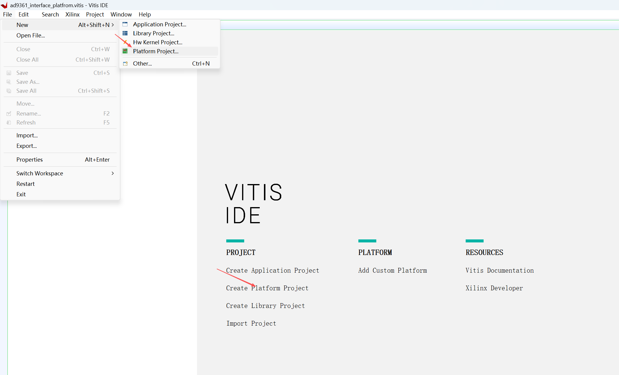
创建platfrom工程
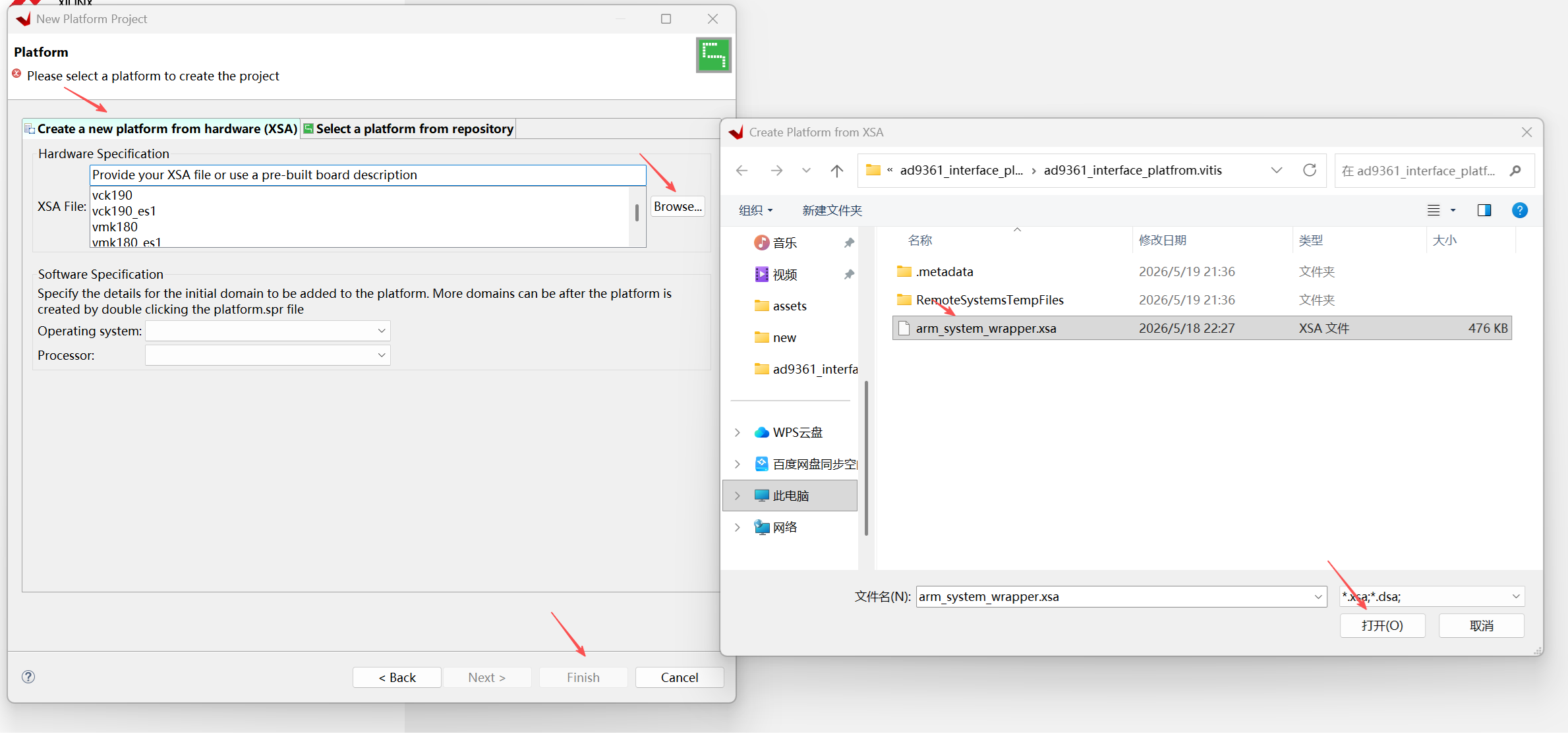
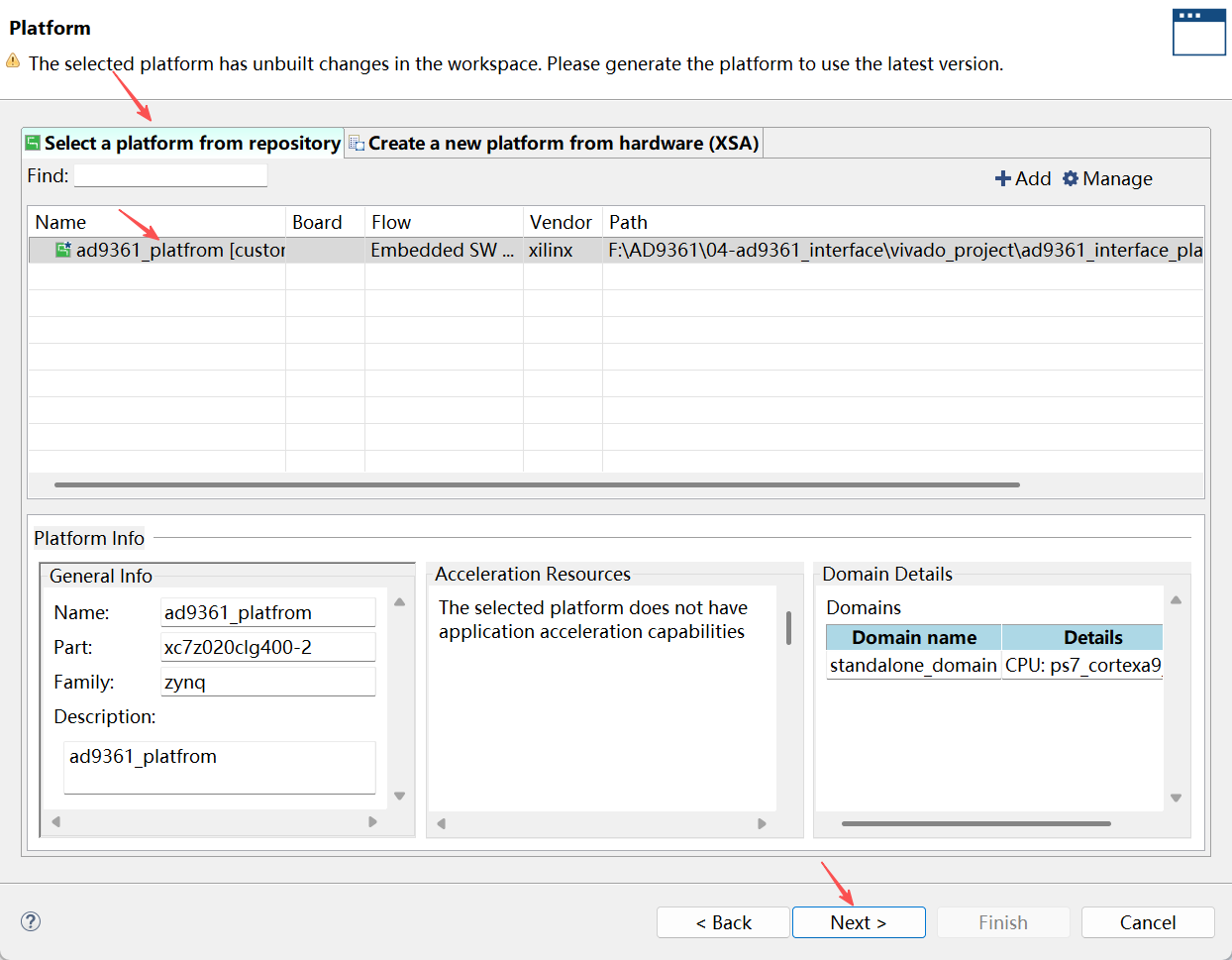
- 打开创建platfrom工程的向导
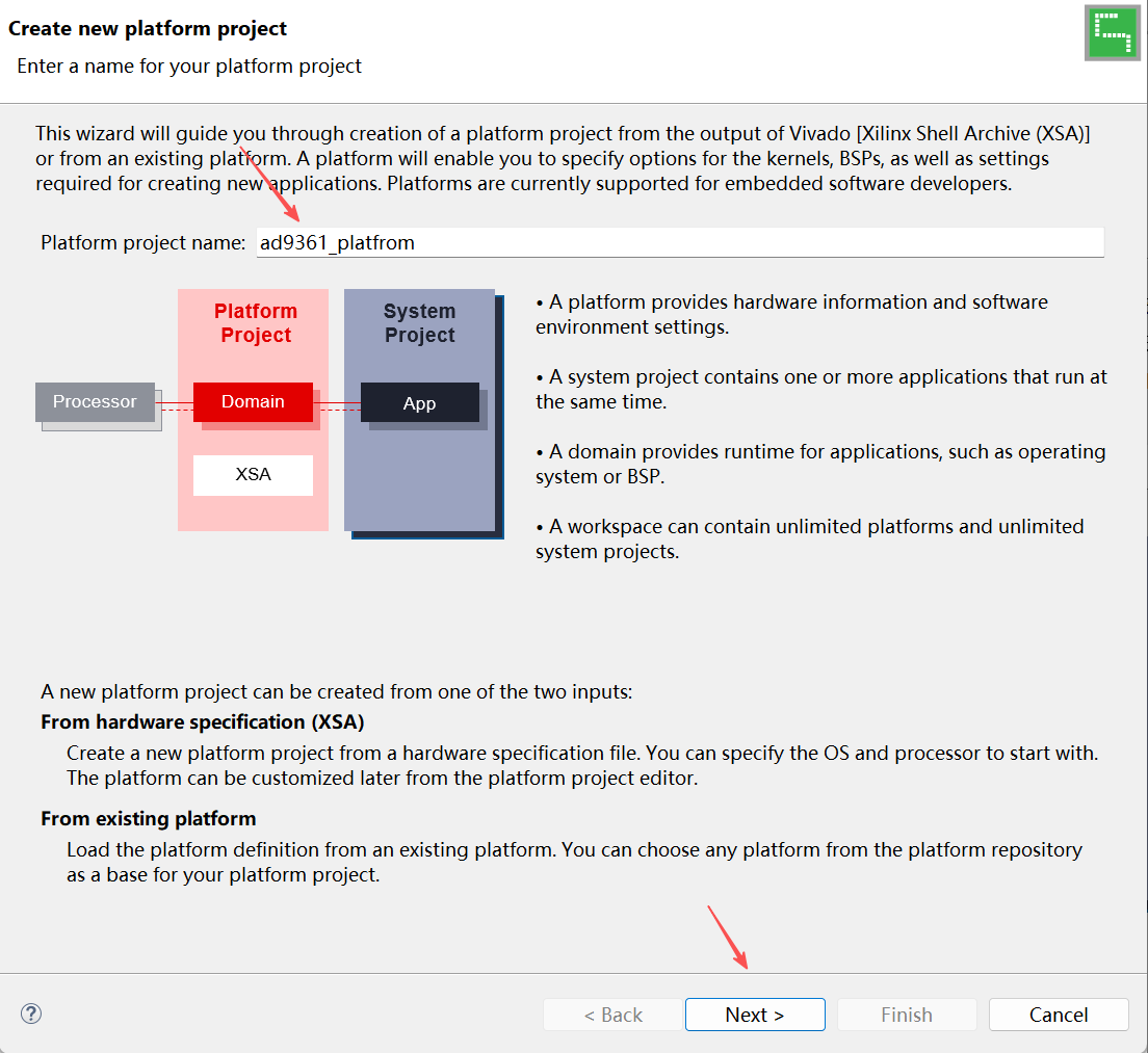
- 输入平台工程名称,然后进入下一步
- 选择上以章节导出的xsa文件,然后点击完成
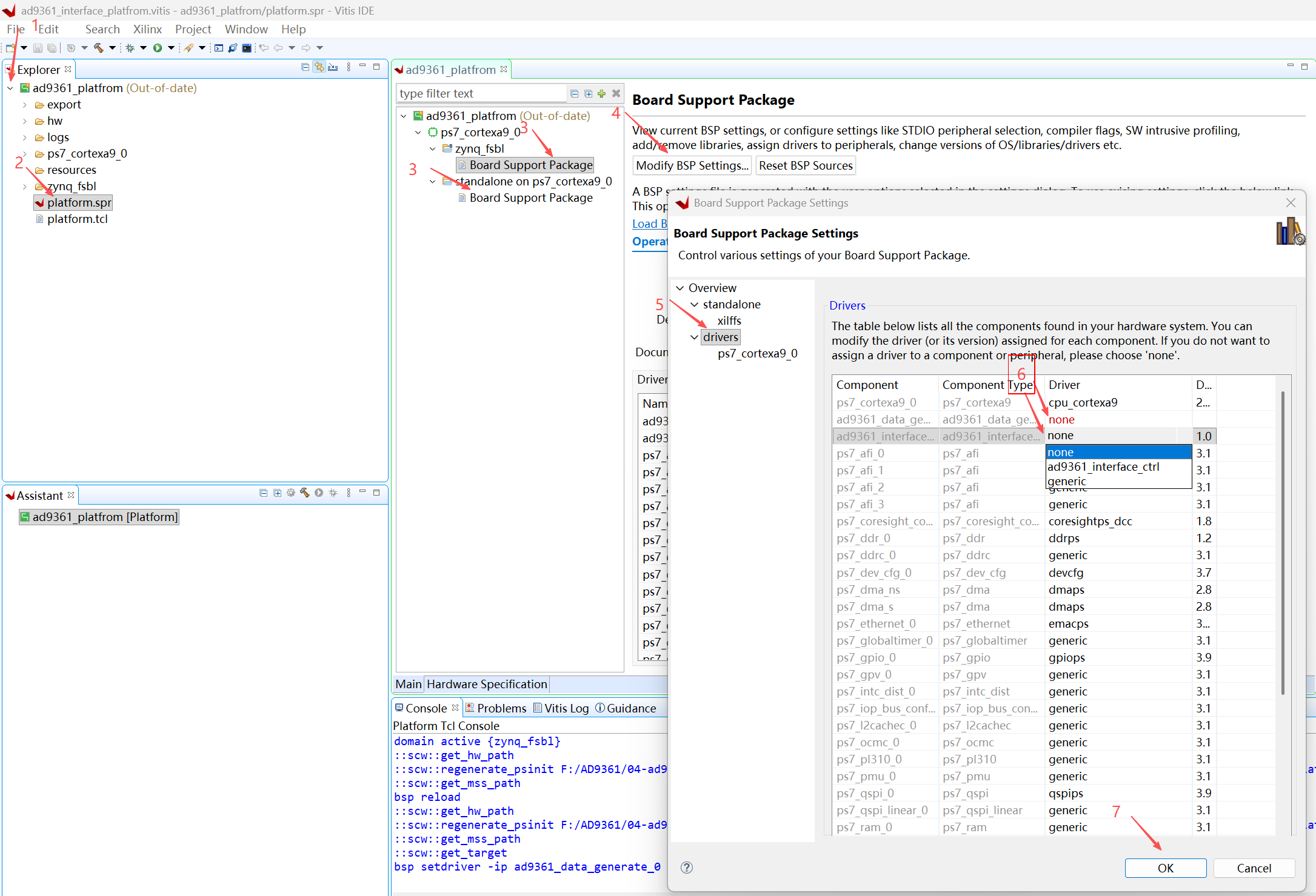
- 配置platfrom,将"zynq_fsbl"的"Board Support Package"和"standalone_ps7_cortexa9_0"的"Board Support Package"中的"ad9361_data_generate_0"和"ad9361_interface_ctrl_0"的Driver配置为none。
创建Application工程
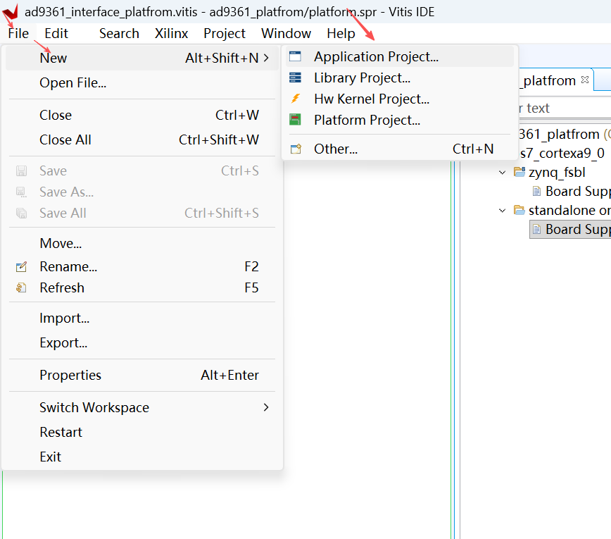
- 打开创建Application工程的向导
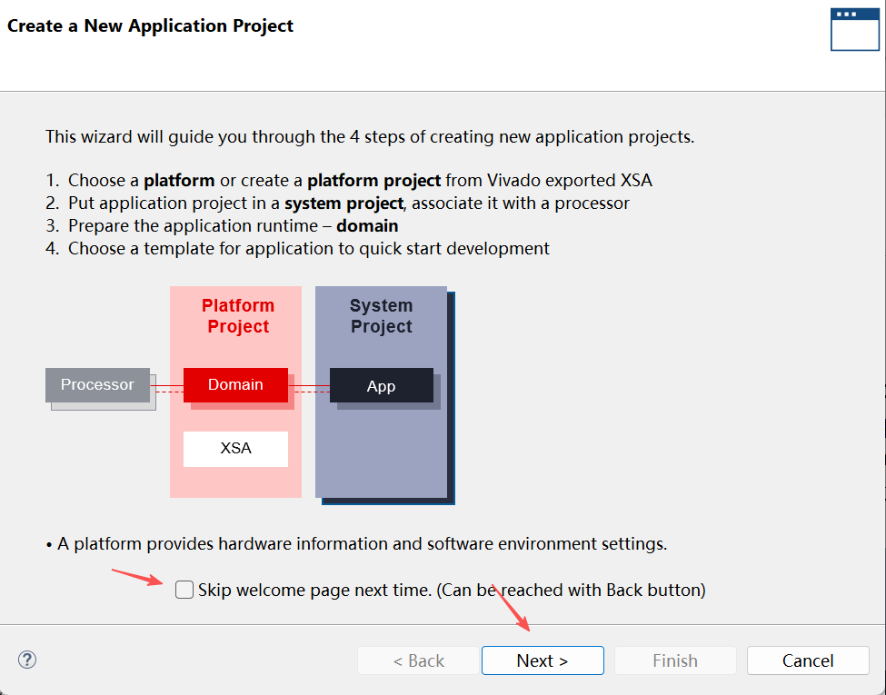
- 跳过引导界面,可以勾选"Skip welcome page next time",这样下次自动跳过该界面
- 选择所依赖的平台工程,然后进入下一步
- 输入工程名称,然后进入下一步
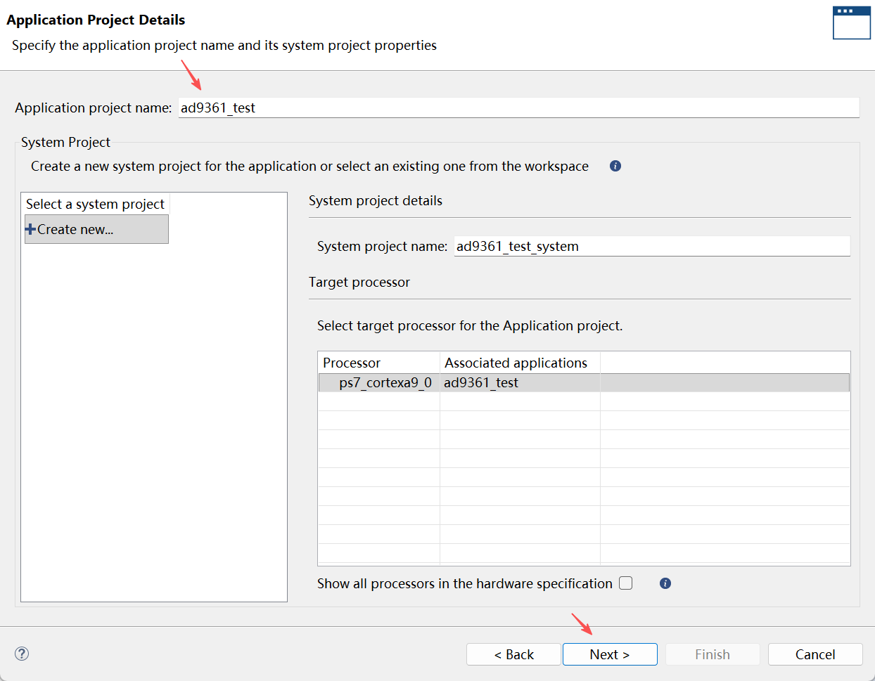
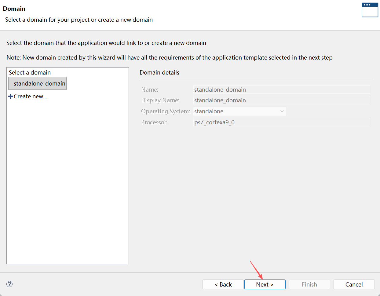
- 所有参数保持默认,直接进入下一步
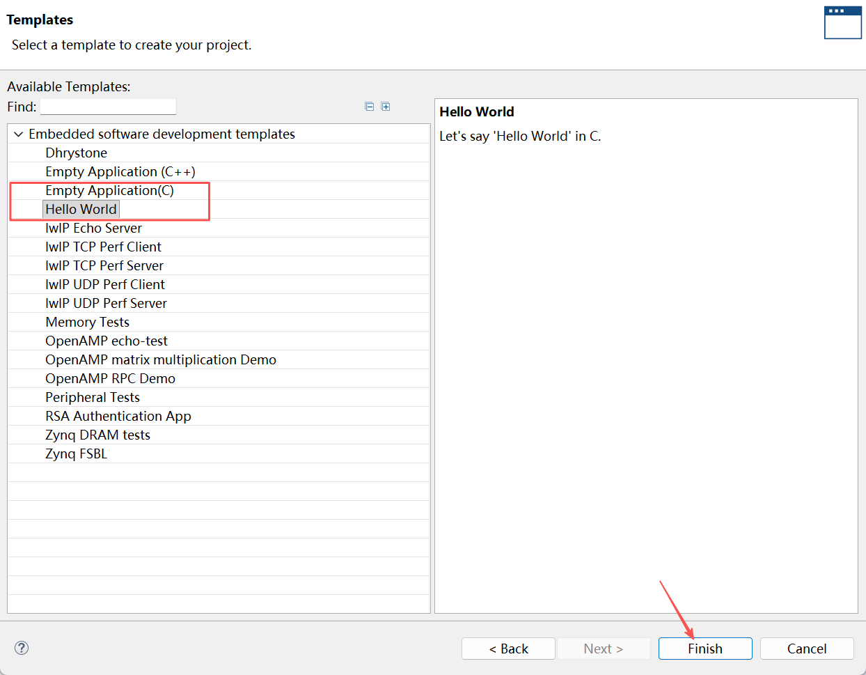
- 选择工程模板,建议选择hello word或者空工程,然后点击完成
往Application工程添加AD9361官方代码
-
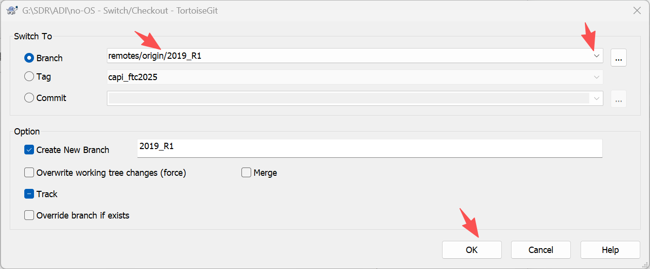
从github下载AD9361官方代码,然后切换到"origin/2019_R1"分支,有关ADI官方代码的使用可以参考ADI的官方文档
-
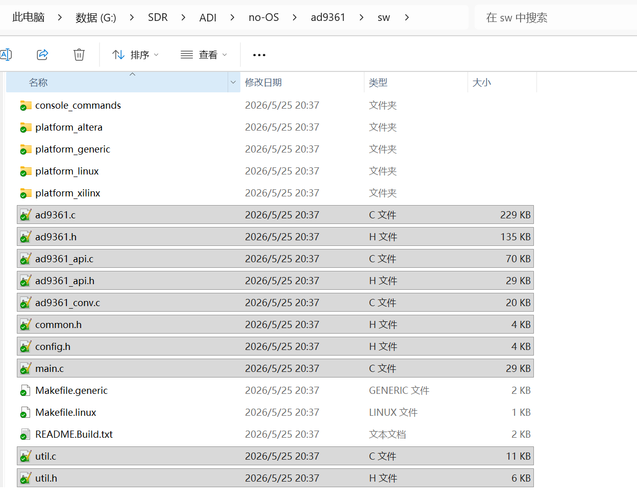
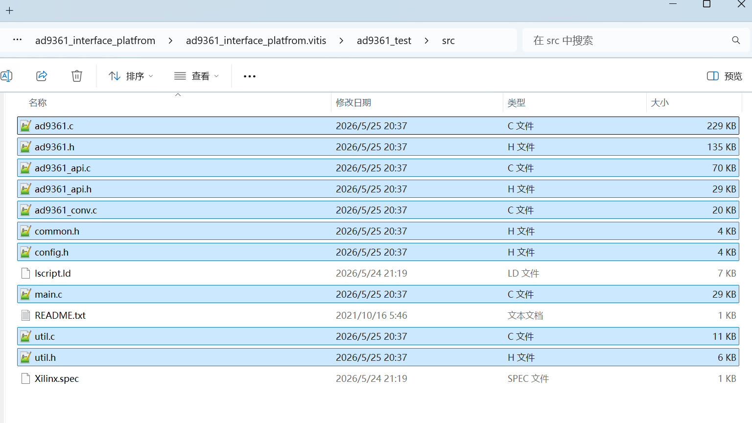
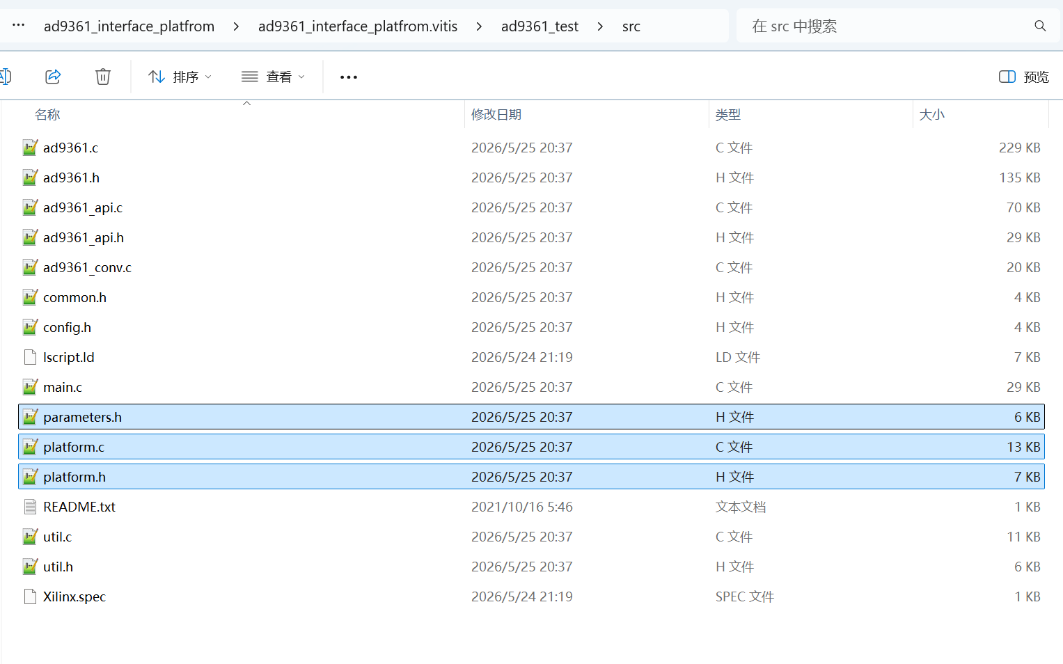
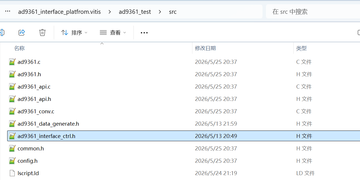
将no-OS\ad9361\sw下的ad9361.c、ad9361.h等文件复制到Application工程的src目录下
-
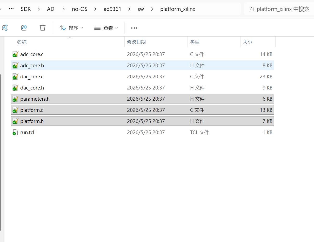
将no-OS\ad9361\sw\platform_xilinx下的platform.h、platform.c、parameters.h复制到Application工程的src目录下
-
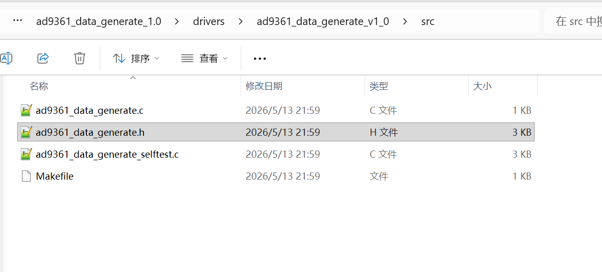
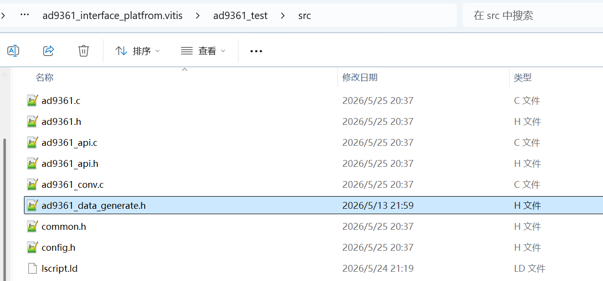
将ad9361_data_generate_1.0 IP核drivers\ad9361_data_generate_v1_0\src目录中的ad9361_data_generate.h复制到Application工程的src目录下
-
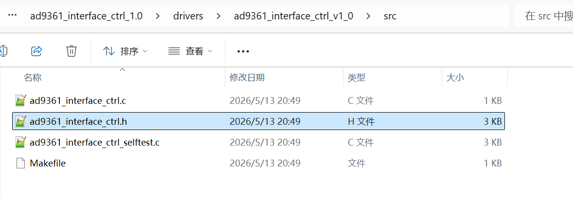
将ad9361_interface_ctrl_1.0 IP核drivers\ad9361_interface_ctrl_v1_0\src目录中的ad9361_interface_ctrl.h复制到Application工程的src目录下
-
修改parameters.h文件为如下内容,这个文件本是包含有些ADI自定义DMA的配置核GPIO的配置,我这里没有使用ADI的自定义DMA,GPIO也是根据开发板原理图重新约束的。
c
#ifndef __PARAMETERS_H__
#define __PARAMETERS_H__

#include <xparameters.h>

#define GPIO_DEVICE_ID		XPAR_PS7_GPIO_0_DEVICE_ID
#define SPI_DEVICE_ID		XPAR_PS7_SPI_0_DEVICE_ID

#define CAT_CTRL_OUT0		(54 + 0)
#define CAT_CTRL_OUT1		(54 + 1)
#define CAT_CTRL_OUT2		(54 + 2)
#define CAT_CTRL_OUT3		(54 + 3)
#define CAT_CTRL_OUT4		(54 + 4)
#define CAT_CTRL_OUT5		(54 + 5)
#define CAT_CTRL_OUT6		(54 + 6)
#define CAT_CTRL_OUT7		(54 + 7)
#define CAT_CTRL_IN0		(54 + 8)
#define CAT_CTRL_IN1		(54 + 9)
#define CAT_CTRL_IN2		(54 + 10)
#define CAT_CTRL_IN3		(54 + 11)
#define CAT_TXNRX			(54 + 12)
#define CAT_ENABLE			(54 + 13)
#define CAT_ENAGC			(54 + 14)
#define CAT_SYNC			(54 + 15)
#define CAT_RSTn			(54 + 16)

#define TX2_AMP_EN			(54 + 17)
#define TX1_AMP_EN			(54 + 18)
#define RX2_LED				(54 + 19)
#define RX1_LED				(54 + 20)

#endif // __PARAMETERS_H__- 修改platform.c文件,将ADI自定义IP核相关的代码删除
c
/******************************************************************************/
/***************************** Include Files **********************************/
/******************************************************************************/
#include <stdint.h>
#include <xparameters.h>
#ifdef _XPARAMETERS_PS_H_
#include <xgpiops.h>
#include <xspips.h>
#else
#include <xgpio.h>
#include <xgpio_l.h>
#include <xspi.h>
#endif
#include "util.h"
#include "platform.h"
#ifdef _XPARAMETERS_PS_H_
#include <sleep.h>
#else
static inline void usleep(unsigned long usleep)
{
	unsigned long delay = 0;

	for(delay = 0; delay < usleep * 10; delay++);
}
#endif

/******************************************************************************/
/************************ Variables Definitions *******************************/
/******************************************************************************/
#ifdef _XPARAMETERS_PS_H_
XSpiPs_Config	*spi_config;
XSpiPs			spi_instance;
XGpioPs_Config	*gpio_config;
XGpioPs			gpio_instance;
#else
XSpi_Config		*spi_config;
XSpi			spi_instance;
XGpio_Config	*gpio_config;
#endif

/***************************************************************************//**
 * @brief spi_init
*******************************************************************************/
int32_t spi_init(uint32_t device_id,
		 uint8_t  clk_pha,
		 uint8_t  clk_pol)
{

	uint32_t base_addr	 = 0;
	uint32_t spi_options = 0;
#ifdef _XPARAMETERS_PS_H_

	spi_config = XSpiPs_LookupConfig(device_id);
	base_addr = spi_config->BaseAddress;

	XSpiPs_CfgInitialize(&spi_instance, spi_config, base_addr);

	spi_options = XSPIPS_MASTER_OPTION |
		      (clk_pol ? XSPIPS_CLK_ACTIVE_LOW_OPTION : 0) |
		      (clk_pha ? XSPIPS_CLK_PHASE_1_OPTION : 0) |
		      XSPIPS_FORCE_SSELECT_OPTION;

	XSpiPs_SetOptions(&spi_instance, spi_options);

	XSpiPs_SetClkPrescaler(&spi_instance, XSPIPS_CLK_PRESCALE_256);
#else
	XSpi_Initialize(&spi_instance, device_id);
	XSpi_Stop(&spi_instance);
	spi_config = XSpi_LookupConfig(device_id);
	base_addr = spi_config->BaseAddress;
	XSpi_CfgInitialize(&spi_instance, spi_config, base_addr);
	spi_options = XSP_MASTER_OPTION |
		      XSP_CLK_PHASE_1_OPTION |
		      XSP_MANUAL_SSELECT_OPTION;
	XSpi_SetOptions(&spi_instance, spi_options);
	XSpi_Start(&spi_instance);
	XSpi_IntrGlobalDisable(&spi_instance);
	XSpi_SetSlaveSelect(&spi_instance, 1);
#endif
	return SUCCESS;
}

/***************************************************************************//**
 * @brief spi_read
*******************************************************************************/
int32_t spi_read(struct spi_device *spi,
		 uint8_t *data,
		 uint8_t bytes_number)
{
#ifdef _XPARAMETERS_PS_H_
	XSpiPs_SetSlaveSelect(&spi_instance, (spi->id_no == 0 ? 0 : 1));

	XSpiPs_PolledTransfer(&spi_instance, data, data, bytes_number);
#else
	uint32_t cnt = 0;
#if defined(XPAR_AXI_SPI_0_DEVICE_ID) || defined(XPAR_SPI_0_DEVICE_ID)
	uint8_t send_buffer[20];

	for(cnt = 0; cnt < bytes_number; cnt++) {
		send_buffer[cnt] = data[cnt];
	}

	XSpi_Transfer(&spi_instance, send_buffer, data, bytes_number);
#else
	Xil_Out32((spi_instance.BaseAddr + 0x60), 0x1e6);
	Xil_Out32((spi_instance.BaseAddr + 0x70), 0x000);
	while(cnt < bytes_number) {
		Xil_Out32((spi_instance.BaseAddr + 0x68), data[cnt]);
		Xil_Out32((spi_instance.BaseAddr + 0x60), 0x096);
		do {
			usleep(100);
		} while ((Xil_In32((spi_instance.BaseAddr + 0x64)) & 0x4) == 0x0);
		Xil_Out32((spi_instance.BaseAddr + 0x60), 0x186);
		data[cnt] = Xil_In32(spi_instance.BaseAddr + 0x6c);
		cnt++;
	}
	Xil_Out32((spi_instance.BaseAddr + 0x70), 0x001);
	Xil_Out32((spi_instance.BaseAddr + 0x60), 0x180);
#endif
#endif
	return SUCCESS;
}

/***************************************************************************//**
 * @brief spi_write_then_read
*******************************************************************************/
int spi_write_then_read(struct spi_device *spi,
			const unsigned char *txbuf, unsigned n_tx,
			unsigned char *rxbuf, unsigned n_rx)
{
	uint8_t buffer[20] = {0x00, 0x00, 0x00, 0x00, 0x00, 0x00, 0x00, 0x00,
			      0x00, 0x00, 0x00, 0x00, 0x00, 0x00, 0x00, 0x00,
			      0x00, 0x00, 0x00, 0x00
			     };
	uint8_t byte;

	for(byte = 0; byte < n_tx; byte++) {
		buffer[byte] = (unsigned char)txbuf[byte];
	}
	spi_read(spi, buffer, n_tx + n_rx);
	for(byte = n_tx; byte < n_tx + n_rx; byte++) {
		rxbuf[byte - n_tx] = buffer[byte];
	}

	return SUCCESS;
}

/***************************************************************************//**
 * @brief gpio_init
*******************************************************************************/
void gpio_init(uint32_t device_id)
{
#ifdef _XPARAMETERS_PS_H_
	gpio_config = XGpioPs_LookupConfig(device_id);
	XGpioPs_CfgInitialize(&gpio_instance, gpio_config, gpio_config->BaseAddr);
#else
	gpio_config = XGpio_LookupConfig(device_id);
#endif
}

/***************************************************************************//**
 * @brief gpio_direction
*******************************************************************************/
void gpio_direction(uint8_t pin, uint8_t direction)
{
#ifdef _XPARAMETERS_PS_H_
	XGpioPs_SetDirectionPin(&gpio_instance, pin, direction);
	XGpioPs_SetOutputEnablePin(&gpio_instance, pin, 1);
#else
	uint32_t config = 0;
	uint32_t tri_reg_addr;

	if (pin >= 32) {
		tri_reg_addr = XGPIO_TRI2_OFFSET;
		pin -= 32;
	} else
		tri_reg_addr = XGPIO_TRI_OFFSET;

	config = Xil_In32((gpio_config->BaseAddress + tri_reg_addr));
	if(direction) {
		config &= ~(1 << pin);
	} else {
		config |= (1 << pin);
	}
	Xil_Out32((gpio_config->BaseAddress + tri_reg_addr), config);
#endif
}

/***************************************************************************//**
 * @brief gpio_is_valid
*******************************************************************************/
bool gpio_is_valid(int number)
{
	if(number >= 0)
		return 1;
	else
		return 0;
}

/***************************************************************************//**
 * @brief gpio_data
*******************************************************************************/
void gpio_data(uint8_t pin, uint8_t data)
{
#ifdef _XPARAMETERS_PS_H_
	XGpioPs_WritePin(&gpio_instance, pin, data);
#else
	uint32_t config = 0;
	uint32_t data_reg_addr;

	if (pin >= 32) {
		data_reg_addr = XGPIO_DATA2_OFFSET;
		pin -= 32;
	} else
		data_reg_addr = XGPIO_DATA_OFFSET;

	config = Xil_In32((gpio_config->BaseAddress + data_reg_addr));
	if(data) {
		config |= (1 << pin);
	} else {
		config &= ~(1 << pin);
	}
	Xil_Out32((gpio_config->BaseAddress + data_reg_addr), config);
#endif
}

/***************************************************************************//**
 * @brief gpio_set_value
*******************************************************************************/
void gpio_set_value(unsigned gpio, int value)
{
	gpio_data(gpio, value);
}

/***************************************************************************//**
 * @brief udelay
*******************************************************************************/
void udelay(unsigned long usecs)
{
	usleep(usecs);
}

/***************************************************************************//**
 * @brief mdelay
*******************************************************************************/
void mdelay(unsigned long msecs)
{
	usleep(msecs * 1000);
}

/***************************************************************************//**
 * @brief msleep_interruptible
*******************************************************************************/
unsigned long msleep_interruptible(unsigned int msecs)
{
	mdelay(msecs);

	return 0;
}- 修改config.h文件,使能XILINX_PLATFORM宏定义和AXI_ADC_NOT_PRESENT宏定义
c
#ifndef CONFIG_H_
#define CONFIG_H_

#define HAVE_VERBOSE_MESSAGES /* Recommended during development prints errors and warnings */
//#define HAVE_DEBUG_MESSAGES /* For Debug purposes only */

/*
 * In case memory footprint is a concern these options allow
 * to disable unused functionality which may free up a few kb
 */

#define HAVE_SPLIT_GAIN_TABLE	1 /* only set to 0 in case split_gain_table_mode_enable = 0*/
#define HAVE_TDD_SYNTH_TABLE	1 /* only set to 0 in case split_gain_table_mode_enable = 0*/

#define AD9361_DEVICE			1 /* set it 1 if AD9361 device is used, 0 otherwise */
#define AD9364_DEVICE			0 /* set it 1 if AD9364 device is used, 0 otherwise */
#define AD9363A_DEVICE			0 /* set it 1 if AD9363A device is used, 0 otherwise */

//#define CONSOLE_COMMANDS
#define XILINX_PLATFORM
//#define ALTERA_PLATFORM
//#define FMCOMMS5
//#define ADI_RF_SOM
//#define ADI_RF_SOM_CMOS
//#define ADC_DMA_EXAMPLE
//#define ADC_DMA_IRQ_EXAMPLE
//#define DAC_DMA_EXAMPLE
#define AXI_ADC_NOT_PRESENT
//#define TDD_SWITCH_STATE_EXAMPLE

#endif- 创建radio_set.h文件,将main.c中的AD9361_InitParam default_init_param、AD9361_RXFIRConfig rx_fir_config、AD9361_TXFIRConfig tx_fir_config、struct ad9361_rf_phy *ad9361_phy复制到radio_set.h文件并作如下修改。
c
#ifndef _RADIO_SET_H_
#define _RADIO_SET_H_

struct ad9361_rf_phy *ad9361_phy;

//sample rate
uint32_t sample_rate = 40e6;
//lo
uint64_t tx_lo_freq = 1500e6;
uint64_t rx_lo_freq = 1500e6;
//bandwidth
uint32_t bandwidth = 20e6;
//rx channel gain
int32_t rx_gain = 8;
//rx channel att
uint32_t tx_att = 10000;

AD9361_InitParam default_init_param = {
	/* Device selection */
	ID_AD9361,	// dev_sel
	/* Identification number */
	0,		//id_no
	/* Reference Clock */
	40000000UL,	//reference_clk_rate
	/* Base Configuration */
	0,		//two_rx_two_tx_mode_enable *** adi,2rx-2tx-mode-enable
	0,		//one_rx_one_tx_mode_use_rx_num *** adi,1rx-1tx-mode-use-rx-num
	0,		//one_rx_one_tx_mode_use_tx_num *** adi,1rx-1tx-mode-use-tx-num
	1,		//frequency_division_duplex_mode_enable *** adi,frequency-division-duplex-mode-enable
	0,		//frequency_division_duplex_independent_mode_enable *** adi,frequency-division-duplex-independent-mode-enable
	0,		//tdd_use_dual_synth_mode_enable *** adi,tdd-use-dual-synth-mode-enable
	0,		//tdd_skip_vco_cal_enable *** adi,tdd-skip-vco-cal-enable
	0,		//tx_fastlock_delay_ns *** adi,tx-fastlock-delay-ns
	0,		//rx_fastlock_delay_ns *** adi,rx-fastlock-delay-ns
	0,		//rx_fastlock_pincontrol_enable *** adi,rx-fastlock-pincontrol-enable
	0,		//tx_fastlock_pincontrol_enable *** adi,tx-fastlock-pincontrol-enable
	0,		//external_rx_lo_enable *** adi,external-rx-lo-enable
	0,		//external_tx_lo_enable *** adi,external-tx-lo-enable
	5,		//dc_offset_tracking_update_event_mask *** adi,dc-offset-tracking-update-event-mask
	6,		//dc_offset_attenuation_high_range *** adi,dc-offset-attenuation-high-range
	5,		//dc_offset_attenuation_low_range *** adi,dc-offset-attenuation-low-range
	0x28,	//dc_offset_count_high_range *** adi,dc-offset-count-high-range
	0x32,	//dc_offset_count_low_range *** adi,dc-offset-count-low-range
	0,		//split_gain_table_mode_enable *** adi,split-gain-table-mode-enable
	MAX_SYNTH_FREF,	//trx_synthesizer_target_fref_overwrite_hz *** adi,trx-synthesizer-target-fref-overwrite-hz
	0,		// qec_tracking_slow_mode_enable *** adi,qec-tracking-slow-mode-enable
	/* ENSM Control */
	0,		//ensm_enable_pin_pulse_mode_enable *** adi,ensm-enable-pin-pulse-mode-enable
	0,		//ensm_enable_txnrx_control_enable *** adi,ensm-enable-txnrx-control-enable
	/* LO Control */
	2400000000UL,	//rx_synthesizer_frequency_hz *** adi,rx-synthesizer-frequency-hz
	2400000000UL,	//tx_synthesizer_frequency_hz *** adi,tx-synthesizer-frequency-hz
	1,				//tx_lo_powerdown_managed_enable *** adi,tx-lo-powerdown-managed-enable
	/* Rate & BW Control */
	{ 1280000000, 320000000, 160000000, 80000000, 40000000, 40000000 },	//uint32_t	rx_path_clock_frequencies[6] *** adi,rx-path-clock-frequencies
	{ 1280000000, 160000000, 160000000, 80000000, 40000000, 40000000 },	//uint32_t	tx_path_clock_frequencies[6] *** adi,tx-path-clock-frequencies
	20000000,//rf_rx_bandwidth_hz *** adi,rf-rx-bandwidth-hz
	20000000,//rf_tx_bandwidth_hz *** adi,rf-tx-bandwidth-hz
	/* RF Port Control */
	0,		//rx_rf_port_input_select *** adi,rx-rf-port-input-select
	0,		//tx_rf_port_input_select *** adi,tx-rf-port-input-select
	/* TX Attenuation Control */
	10000,	//tx_attenuation_mdB *** adi,tx-attenuation-mdB
	0,		//update_tx_gain_in_alert_enable *** adi,update-tx-gain-in-alert-enable
	/* Reference Clock Control */
	0,		//xo_disable_use_ext_refclk_enable *** adi,xo-disable-use-ext-refclk-enable
	{8, 5920},	//dcxo_coarse_and_fine_tune[2] *** adi,dcxo-coarse-and-fine-tune
	ADC_CLK_DIV_16,	//clk_output_mode_select *** adi,clk-output-mode-select
	/* Gain Control */
	0,		//gc_rx1_mode *** adi,gc-rx1-mode
	0,		//gc_rx2_mode *** adi,gc-rx2-mode
	58,		//gc_adc_large_overload_thresh *** adi,gc-adc-large-overload-thresh
	4,		//gc_adc_ovr_sample_size *** adi,gc-adc-ovr-sample-size
	47,		//gc_adc_small_overload_thresh *** adi,gc-adc-small-overload-thresh
	8192,	//gc_dec_pow_measurement_duration *** adi,gc-dec-pow-measurement-duration
	0,		//gc_dig_gain_enable *** adi,gc-dig-gain-enable
	800,	//gc_lmt_overload_high_thresh *** adi,gc-lmt-overload-high-thresh
	704,	//gc_lmt_overload_low_thresh *** adi,gc-lmt-overload-low-thresh
	24,		//gc_low_power_thresh *** adi,gc-low-power-thresh
	15,		//gc_max_dig_gain *** adi,gc-max-dig-gain
	/* Gain MGC Control */
	2,		//mgc_dec_gain_step *** adi,mgc-dec-gain-step
	2,		//mgc_inc_gain_step *** adi,mgc-inc-gain-step
	0,		//mgc_rx1_ctrl_inp_enable *** adi,mgc-rx1-ctrl-inp-enable
	0,		//mgc_rx2_ctrl_inp_enable *** adi,mgc-rx2-ctrl-inp-enable
	0,		//mgc_split_table_ctrl_inp_gain_mode *** adi,mgc-split-table-ctrl-inp-gain-mode
	/* Gain AGC Control */
	10,		//agc_adc_large_overload_exceed_counter *** adi,agc-adc-large-overload-exceed-counter
	2,		//agc_adc_large_overload_inc_steps *** adi,agc-adc-large-overload-inc-steps
	0,		//agc_adc_lmt_small_overload_prevent_gain_inc_enable *** adi,agc-adc-lmt-small-overload-prevent-gain-inc-enable
	10,		//agc_adc_small_overload_exceed_counter *** adi,agc-adc-small-overload-exceed-counter
	4,		//agc_dig_gain_step_size *** adi,agc-dig-gain-step-size
	3,		//agc_dig_saturation_exceed_counter *** adi,agc-dig-saturation-exceed-counter
	1000,	// agc_gain_update_interval_us *** adi,agc-gain-update-interval-us
	0,		//agc_immed_gain_change_if_large_adc_overload_enable *** adi,agc-immed-gain-change-if-large-adc-overload-enable
	0,		//agc_immed_gain_change_if_large_lmt_overload_enable *** adi,agc-immed-gain-change-if-large-lmt-overload-enable
	10,		//agc_inner_thresh_high *** adi,agc-inner-thresh-high
	1,		//agc_inner_thresh_high_dec_steps *** adi,agc-inner-thresh-high-dec-steps
	12,		//agc_inner_thresh_low *** adi,agc-inner-thresh-low
	1,		//agc_inner_thresh_low_inc_steps *** adi,agc-inner-thresh-low-inc-steps
	10,		//agc_lmt_overload_large_exceed_counter *** adi,agc-lmt-overload-large-exceed-counter
	2,		//agc_lmt_overload_large_inc_steps *** adi,agc-lmt-overload-large-inc-steps
	10,		//agc_lmt_overload_small_exceed_counter *** adi,agc-lmt-overload-small-exceed-counter
	5,		//agc_outer_thresh_high *** adi,agc-outer-thresh-high
	2,		//agc_outer_thresh_high_dec_steps *** adi,agc-outer-thresh-high-dec-steps
	18,		//agc_outer_thresh_low *** adi,agc-outer-thresh-low
	2,		//agc_outer_thresh_low_inc_steps *** adi,agc-outer-thresh-low-inc-steps
	1,		//agc_attack_delay_extra_margin_us; *** adi,agc-attack-delay-extra-margin-us
	0,		//agc_sync_for_gain_counter_enable *** adi,agc-sync-for-gain-counter-enable
	/* Fast AGC */
	64,		//fagc_dec_pow_measuremnt_duration ***  adi,fagc-dec-pow-measurement-duration
	260,	//fagc_state_wait_time_ns ***  adi,fagc-state-wait-time-ns
	/* Fast AGC - Low Power */
	0,		//fagc_allow_agc_gain_increase ***  adi,fagc-allow-agc-gain-increase-enable
	5,		//fagc_lp_thresh_increment_time ***  adi,fagc-lp-thresh-increment-time
	1,		//fagc_lp_thresh_increment_steps ***  adi,fagc-lp-thresh-increment-steps
	/* Fast AGC - Lock Level */
	1,		//fagc_lock_level_lmt_gain_increase_en ***  adi,fagc-lock-level-lmt-gain-increase-enable
	5,		//fagc_lock_level_gain_increase_upper_limit ***  adi,fagc-lock-level-gain-increase-upper-limit
	/* Fast AGC - Peak Detectors and Final Settling */
	1,		//fagc_lpf_final_settling_steps ***  adi,fagc-lpf-final-settling-steps
	1,		//fagc_lmt_final_settling_steps ***  adi,fagc-lmt-final-settling-steps
	3,		//fagc_final_overrange_count ***  adi,fagc-final-overrange-count
	/* Fast AGC - Final Power Test */
	0,		//fagc_gain_increase_after_gain_lock_en ***  adi,fagc-gain-increase-after-gain-lock-enable
	/* Fast AGC - Unlocking the Gain */
	0,		//fagc_gain_index_type_after_exit_rx_mode ***  adi,fagc-gain-index-type-after-exit-rx-mode
	1,		//fagc_use_last_lock_level_for_set_gain_en ***  adi,fagc-use-last-lock-level-for-set-gain-enable
	1,		//fagc_rst_gla_stronger_sig_thresh_exceeded_en ***  adi,fagc-rst-gla-stronger-sig-thresh-exceeded-enable
	5,		//fagc_optimized_gain_offset ***  adi,fagc-optimized-gain-offset
	10,		//fagc_rst_gla_stronger_sig_thresh_above_ll ***  adi,fagc-rst-gla-stronger-sig-thresh-above-ll
	1,		//fagc_rst_gla_engergy_lost_sig_thresh_exceeded_en ***  adi,fagc-rst-gla-engergy-lost-sig-thresh-exceeded-enable
	1,		//fagc_rst_gla_engergy_lost_goto_optim_gain_en ***  adi,fagc-rst-gla-engergy-lost-goto-optim-gain-enable
	10,		//fagc_rst_gla_engergy_lost_sig_thresh_below_ll ***  adi,fagc-rst-gla-engergy-lost-sig-thresh-below-ll
	8,		//fagc_energy_lost_stronger_sig_gain_lock_exit_cnt ***  adi,fagc-energy-lost-stronger-sig-gain-lock-exit-cnt
	1,		//fagc_rst_gla_large_adc_overload_en ***  adi,fagc-rst-gla-large-adc-overload-enable
	1,		//fagc_rst_gla_large_lmt_overload_en ***  adi,fagc-rst-gla-large-lmt-overload-enable
	0,		//fagc_rst_gla_en_agc_pulled_high_en ***  adi,fagc-rst-gla-en-agc-pulled-high-enable
	0,		//fagc_rst_gla_if_en_agc_pulled_high_mode ***  adi,fagc-rst-gla-if-en-agc-pulled-high-mode
	64,		//fagc_power_measurement_duration_in_state5 ***  adi,fagc-power-measurement-duration-in-state5
	/* RSSI Control */
	1,		//rssi_delay *** adi,rssi-delay
	1000,	//rssi_duration *** adi,rssi-duration
	3,		//rssi_restart_mode *** adi,rssi-restart-mode
	0,		//rssi_unit_is_rx_samples_enable *** adi,rssi-unit-is-rx-samples-enable
	1,		//rssi_wait *** adi,rssi-wait
	/* Aux ADC Control */
	256,	//aux_adc_decimation *** adi,aux-adc-decimation
	40000000UL,	//aux_adc_rate *** adi,aux-adc-rate
	/* AuxDAC Control */
	1,		//aux_dac_manual_mode_enable ***  adi,aux-dac-manual-mode-enable
	0,		//aux_dac1_default_value_mV ***  adi,aux-dac1-default-value-mV
	0,		//aux_dac1_active_in_rx_enable ***  adi,aux-dac1-active-in-rx-enable
	0,		//aux_dac1_active_in_tx_enable ***  adi,aux-dac1-active-in-tx-enable
	0,		//aux_dac1_active_in_alert_enable ***  adi,aux-dac1-active-in-alert-enable
	0,		//aux_dac1_rx_delay_us ***  adi,aux-dac1-rx-delay-us
	0,		//aux_dac1_tx_delay_us ***  adi,aux-dac1-tx-delay-us
	0,		//aux_dac2_default_value_mV ***  adi,aux-dac2-default-value-mV
	0,		//aux_dac2_active_in_rx_enable ***  adi,aux-dac2-active-in-rx-enable
	0,		//aux_dac2_active_in_tx_enable ***  adi,aux-dac2-active-in-tx-enable
	0,		//aux_dac2_active_in_alert_enable ***  adi,aux-dac2-active-in-alert-enable
	0,		//aux_dac2_rx_delay_us ***  adi,aux-dac2-rx-delay-us
	0,		//aux_dac2_tx_delay_us ***  adi,aux-dac2-tx-delay-us
	/* Temperature Sensor Control */
	256,	//temp_sense_decimation *** adi,temp-sense-decimation
	1000,	//temp_sense_measurement_interval_ms *** adi,temp-sense-measurement-interval-ms
	0xCE,	//temp_sense_offset_signed *** adi,temp-sense-offset-signed
	1,		//temp_sense_periodic_measurement_enable *** adi,temp-sense-periodic-measurement-enable
	/* Control Out Setup */
	0xFF,	//ctrl_outs_enable_mask *** adi,ctrl-outs-enable-mask
	0,		//ctrl_outs_index *** adi,ctrl-outs-index
	/* External LNA Control */
	0,		//elna_settling_delay_ns *** adi,elna-settling-delay-ns
	0,		//elna_gain_mdB *** adi,elna-gain-mdB
	0,		//elna_bypass_loss_mdB *** adi,elna-bypass-loss-mdB
	0,		//elna_rx1_gpo0_control_enable *** adi,elna-rx1-gpo0-control-enable
	0,		//elna_rx2_gpo1_control_enable *** adi,elna-rx2-gpo1-control-enable
	0,		//elna_gaintable_all_index_enable *** adi,elna-gaintable-all-index-enable
	/* Digital Interface Control */
	0,		//digital_interface_tune_skip_mode *** adi,digital-interface-tune-skip-mode
	0,		//digital_interface_tune_fir_disable *** adi,digital-interface-tune-fir-disable
	1,		//pp_tx_swap_enable *** adi,pp-tx-swap-enable
	1,		//pp_rx_swap_enable *** adi,pp-rx-swap-enable
	0,		//tx_channel_swap_enable *** adi,tx-channel-swap-enable
	0,		//rx_channel_swap_enable *** adi,rx-channel-swap-enable
	1,		//rx_frame_pulse_mode_enable *** adi,rx-frame-pulse-mode-enable
	0,		//two_t_two_r_timing_enable *** adi,2t2r-timing-enable
	0,		//invert_data_bus_enable *** adi,invert-data-bus-enable
	0,		//invert_data_clk_enable *** adi,invert-data-clk-enable
	0,		//fdd_alt_word_order_enable *** adi,fdd-alt-word-order-enable
	0,		//invert_rx_frame_enable *** adi,invert-rx-frame-enable
	0,		//fdd_rx_rate_2tx_enable *** adi,fdd-rx-rate-2tx-enable
	0,		//swap_ports_enable *** adi,swap-ports-enable
	0,		//single_data_rate_enable *** adi,single-data-rate-enable
	1,		//lvds_mode_enable *** adi,lvds-mode-enable
	0,		//half_duplex_mode_enable *** adi,half-duplex-mode-enable
	0,		//single_port_mode_enable *** adi,single-port-mode-enable
	0,		//full_port_enable *** adi,full-port-enable
	0,		//full_duplex_swap_bits_enable *** adi,full-duplex-swap-bits-enable
	0,		//delay_rx_data *** adi,delay-rx-data
	0,		//rx_data_clock_delay *** adi,rx-data-clock-delay
	4,		//rx_data_delay *** adi,rx-data-delay
	7,		//tx_fb_clock_delay *** adi,tx-fb-clock-delay
	0,		//tx_data_delay *** adi,tx-data-delay
	150,	//lvds_bias_mV *** adi,lvds-bias-mV
	1,		//lvds_rx_onchip_termination_enable *** adi,lvds-rx-onchip-termination-enable
	0,		//rx1rx2_phase_inversion_en *** adi,rx1-rx2-phase-inversion-enable
	0xFF,	//lvds_invert1_control *** adi,lvds-invert1-control
	0x0F,	//lvds_invert2_control *** adi,lvds-invert2-control
	/* GPO Control */
	0,		//gpo0_inactive_state_high_enable *** adi,gpo0-inactive-state-high-enable
	0,		//gpo1_inactive_state_high_enable *** adi,gpo1-inactive-state-high-enable
	0,		//gpo2_inactive_state_high_enable *** adi,gpo2-inactive-state-high-enable
	0,		//gpo3_inactive_state_high_enable *** adi,gpo3-inactive-state-high-enable
	0,		//gpo0_slave_rx_enable *** adi,gpo0-slave-rx-enable
	0,		//gpo0_slave_tx_enable *** adi,gpo0-slave-tx-enable
	0,		//gpo1_slave_rx_enable *** adi,gpo1-slave-rx-enable
	0,		//gpo1_slave_tx_enable *** adi,gpo1-slave-tx-enable
	0,		//gpo2_slave_rx_enable *** adi,gpo2-slave-rx-enable
	0,		//gpo2_slave_tx_enable *** adi,gpo2-slave-tx-enable
	0,		//gpo3_slave_rx_enable *** adi,gpo3-slave-rx-enable
	0,		//gpo3_slave_tx_enable *** adi,gpo3-slave-tx-enable
	0,		//gpo0_rx_delay_us *** adi,gpo0-rx-delay-us
	0,		//gpo0_tx_delay_us *** adi,gpo0-tx-delay-us
	0,		//gpo1_rx_delay_us *** adi,gpo1-rx-delay-us
	0,		//gpo1_tx_delay_us *** adi,gpo1-tx-delay-us
	0,		//gpo2_rx_delay_us *** adi,gpo2-rx-delay-us
	0,		//gpo2_tx_delay_us *** adi,gpo2-tx-delay-us
	0,		//gpo3_rx_delay_us *** adi,gpo3-rx-delay-us
	0,		//gpo3_tx_delay_us *** adi,gpo3-tx-delay-us
	/* Tx Monitor Control */
	37000,	//low_high_gain_threshold_mdB *** adi,txmon-low-high-thresh
	0,		//low_gain_dB *** adi,txmon-low-gain
	24,		//high_gain_dB *** adi,txmon-high-gain
	0,		//tx_mon_track_en *** adi,txmon-dc-tracking-enable
	0,		//one_shot_mode_en *** adi,txmon-one-shot-mode-enable
	511,	//tx_mon_delay *** adi,txmon-delay
	8192,	//tx_mon_duration *** adi,txmon-duration
	2,		//tx1_mon_front_end_gain *** adi,txmon-1-front-end-gain
	2,		//tx2_mon_front_end_gain *** adi,txmon-2-front-end-gain
	48,		//tx1_mon_lo_cm *** adi,txmon-1-lo-cm
	48,		//tx2_mon_lo_cm *** adi,txmon-2-lo-cm
	/* GPIO definitions */
	-1,		//gpio_resetb *** reset-gpios
	/* MCS Sync */
	-1,		//gpio_sync *** sync-gpios
	-1,		//gpio_cal_sw1 *** cal-sw1-gpios
	-1,		//gpio_cal_sw2 *** cal-sw2-gpios
	/* External LO clocks */
	NULL,	//(*ad9361_rfpll_ext_recalc_rate)()
	NULL,	//(*ad9361_rfpll_ext_round_rate)()
	NULL	//(*ad9361_rfpll_ext_set_rate)()
};

AD9361_RXFIRConfig rx_fir_config = {
	3, // rx;
	0, // rx_gain;
	2, // rx_dec;
	{ -15 - 79, -116, -137, -119, -59, 27, 101, 127, 89, 4, -77, -102, -48,
		58, 151, 165, 78, -64, -170, -161, -27, 156, 266, 216, 18, -210,
		-312, -199, 80, 350, 420, 213, -163, -466, -471, -135, 352, 664,
		558, 49, -559, -847, -565, 172, 909, 1118, 564, -485, -1363,
		-1405, -417, 1101, 2163, 1879, 91, -2340, -3829, -2858, 1132,
		7263, 13459, 17341, 17341, 13459, 7263, 1132, -2858, -3829,
		-2340, 91, 1879, 2163, 1101, -417, -1405, -1363, -485, 564,
		1118, 909, 172, -565, -847, -559, 49, 558, 664, 352, -135, -471,
		-466, -163, 213, 420, 350, 80, -199, -312, -210, 18, 216, 266,
		156, -27, -161, -170, -64, 78, 165, 151, 58, -48, -102, -77, 4,
		89, 127, 101, 27, -59, -119, -137, -116, -79, -39, -15 }, // rx_coef[128]
	128, // rx_coef_size
	{ 0, 0, 0, 0, 0, 0 }, //rx_path_clks[6]
	0 // rx_bandwidth
};

AD9361_TXFIRConfig tx_fir_config = {
	3, // tx;
	0, // tx_gain;
	2, // tx_int;
	{ -23, -44, -92, -124, -144, -114, -47, 46, 119, 141, 93, 4, -79, -98,
		-37, 73, 164, 170, 75, -69, -171, -154, -13, 171, 275, 215, 9,
		-218, -311, -187, 97, 363, 421, 203, -177, -471, -464, -118,
		368, 670, 550, 33, -571, -846, -551, 190, 918, 1114, 550, -498,
		-1364, -1394, -402, 1107, 2154, 1863, 84, -2324, -3793, -2826,
		1125, 7188, 13311, 17146, 17146, 13311, 7188, 1125, -2826,
		-3793, -2324, 84, 1863, 2154, 1107, -402, -1394, -1364, -498,
		550, 1114, 918, 190, -551, -846, -571, 33, 550, 670, 368, -118,
		-464, -471, -177, 203, 421, 363, 97, -187, -311, -218, 9, 215,
		275, 171, -13, -154, -171, -69, 75, 170, 164, 73, -37, -98, -79,
		4, 93, 141, 119, 46, -47, -114, -144, -124, -92, -44, -23 }, // tx_coef[128]
	128, // tx_coef_size
	{ 0, 0, 0, 0, 0, 0 }, // tx_path_clks[6]
	0 // tx_bandwidth
};

#endif /* _RADIO_SET_H_ */- 修改main.c文件,只保留AD9361参数化相关的功能
c
#include "config.h"
#include "ad9361_api.h"
#include "parameters.h"
#include "platform.h"
#include "radio_set.h"
#include "xil_io.h"
#include "ad9361_data_generate.h"
#include "ad9361_interface_ctrl.h"
#include <xil_cache.h>


#define AD9361_INTERFACE_CTRL_BASEADDR			0x43C10000
#define AD9361_DATA_GENERATE_BASEADDR			0x43C00000

#define AXI_SLV_REG0_OFFSET 					0
#define AXI_SLV_REG1_OFFSET 					4
#define AXI_SLV_REG2_OFFSET 					8
#define AXI_SLV_REG3_OFFSET 					12

void gpio_initial(void)
{
	gpio_direction(CAT_CTRL_IN0	, 1);
	gpio_direction(CAT_CTRL_IN1	, 1);
	gpio_direction(CAT_CTRL_IN2	, 1);
	gpio_direction(CAT_CTRL_IN3	, 1);
	gpio_direction(CAT_TXNRX	, 1);
	gpio_direction(CAT_ENABLE	, 1);
	gpio_direction(CAT_ENAGC	, 1);
	gpio_direction(CAT_SYNC		, 1);
//	gpio_direction(CAT_RSTn		, 1);

	gpio_direction(TX2_AMP_EN	, 1);
	gpio_direction(TX1_AMP_EN	, 1);
	gpio_direction(RX2_LED		, 1);
	gpio_direction(RX1_LED		, 1);

	gpio_set_value(CAT_CTRL_IN0	, 0);
	gpio_set_value(CAT_CTRL_IN1	, 0);
	gpio_set_value(CAT_CTRL_IN2	, 0);
	gpio_set_value(CAT_CTRL_IN3	, 0);
	gpio_set_value(CAT_TXNRX	, 1);
	gpio_set_value(CAT_ENABLE	, 0);
	gpio_set_value(CAT_ENAGC	, 1);
	gpio_set_value(CAT_SYNC		, 1);
//	gpio_set_value(CAT_RSTn		, 1);

	gpio_set_value(TX2_AMP_EN	, 1);
	gpio_set_value(TX1_AMP_EN	, 1);
	gpio_set_value(RX2_LED		, 1);
	gpio_set_value(RX1_LED		, 1);
}

int main(void)
{
	int32_t val;

	Xil_ICacheEnable();
	Xil_DCacheEnable();

	//ad936x resetpin
	default_init_param.gpio_resetb = CAT_RSTn;
	default_init_param.gpio_sync = -1;
	default_init_param.gpio_cal_sw1 = -1;
	default_init_param.gpio_cal_sw2 = -1;

	//gpio dev initial
	gpio_init(GPIO_DEVICE_ID);
	gpio_direction(default_init_param.gpio_resetb, 1);

	//spi dev initial
	spi_init(SPI_DEVICE_ID, 1, 0);

	//initial ad936x
	ad9361_init(&ad9361_phy, &default_init_param);
	//set fir param
	ad9361_set_tx_fir_config(ad9361_phy, tx_fir_config);
	ad9361_set_rx_fir_config(ad9361_phy, rx_fir_config);
	ad9361_set_tx_fir_en_dis(ad9361_phy, 1);
	ad9361_set_rx_fir_en_dis(ad9361_phy, 1);
	//set sample rate
	ad9361_set_tx_sampling_freq(ad9361_phy, sample_rate);
	ad9361_set_rx_sampling_freq(ad9361_phy, sample_rate);
	//set lo
	ad9361_set_tx_lo_freq(ad9361_phy, tx_lo_freq);
	ad9361_set_rx_lo_freq(ad9361_phy, rx_lo_freq);
	//set bandwidth
	ad9361_set_tx_rf_bandwidth(ad9361_phy, bandwidth);
	ad9361_set_rx_rf_bandwidth(ad9361_phy, bandwidth);
	//set rx channel gain
	ad9361_set_rx_rf_gain(ad9361_phy, 0, rx_gain);
	ad9361_set_rx_rf_gain(ad9361_phy, 1, rx_gain);
	//set tx att
	ad9361_set_tx_attenuation(ad9361_phy, 0, tx_att);
	ad9361_set_tx_attenuation(ad9361_phy, 1, tx_att);
	//read 936x chip id
	val = ad9361_spi_read(ad9361_phy->spi, REG_PRODUCT_ID);
	printf("ad9361_phy,REG_PRODUCT_ID=%d\n\r",val);

	//initial emio pin
	gpio_initial();

	//set idelay
	AD9361_INTERFACE_CTRL_mWriteReg(AD9361_INTERFACE_CTRL_BASEADDR, AXI_SLV_REG1_OFFSET, 8);
	AD9361_INTERFACE_CTRL_mWriteReg(AD9361_INTERFACE_CTRL_BASEADDR, AXI_SLV_REG0_OFFSET, 0x7F);
	usleep(1000*1000);
	//读取idelay ctrl锁定状态
	printf("delay_ctrl_lock=%d\r\n", AD9361_INTERFACE_CTRL_mReadReg(AD9361_INTERFACE_CTRL_BASEADDR, AXI_SLV_REG2_OFFSET));
	//使能data_clk
	AD9361_INTERFACE_CTRL_mWriteReg(AD9361_INTERFACE_CTRL_BASEADDR, AXI_SLV_REG3_OFFSET, 1);
	//设置dds相位步进
	AD9361_DATA_GENERATE_mWriteReg(AD9361_DATA_GENERATE_BASEADDR, AXI_SLV_REG1_OFFSET, 128);
	//使能DDS
	AD9361_DATA_GENERATE_mWriteReg(AD9361_DATA_GENERATE_BASEADDR, AXI_SLV_REG0_OFFSET, 1);

	printf("initial done.\n\r");

	while(1)
	{

	}

	Xil_DCacheDisable();
	Xil_ICacheDisable();

	return 0;
}
ad936x-filter-wizard工具的使用
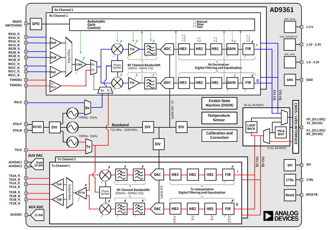
ad936x-filter-wizard是一个matlab程序,用于设计AD9361的TX和RX的数字滤波器,如下时AD9361的内部框图,发射时基带数据先经过数字滤波器再到DAC,接收时ADC采的数据经过数字滤波器处理后再给基带。
下载和安装ad936x-filter-wizard
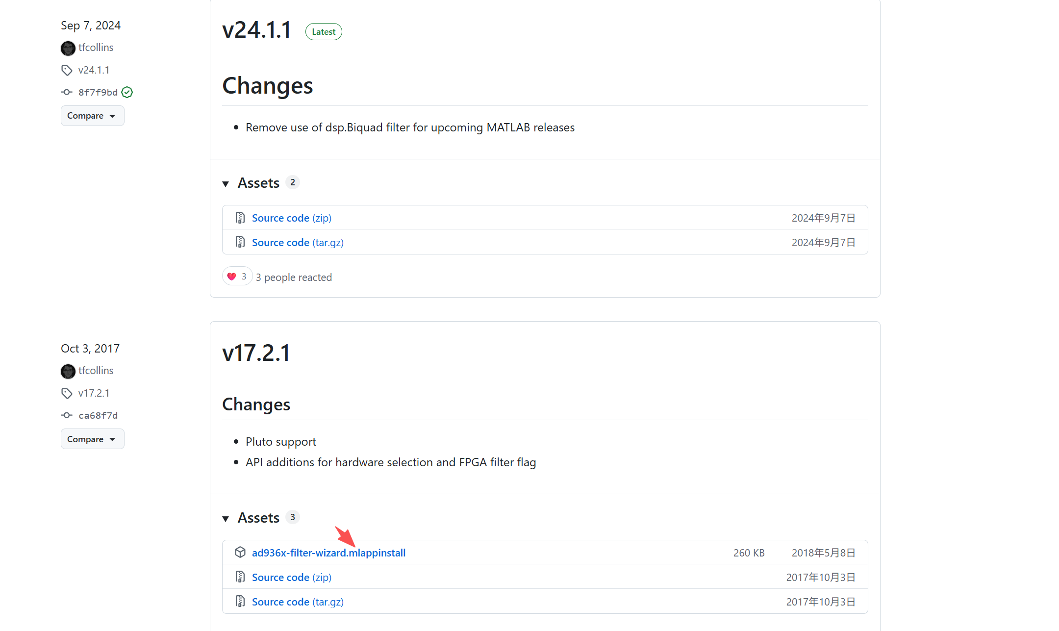
- 下载ad936x-filter-wizard,版本根据自己的matlab进行选择,有些版本还提供了matlab APP安装程序(以".mlappinstall"结束的文件便是),也可以将整个git库克隆到本地然后在切换到对应的版本分支(不过git库没有提供matlab APP安装程序),建议直接下载matlab APP安装程序进行安装
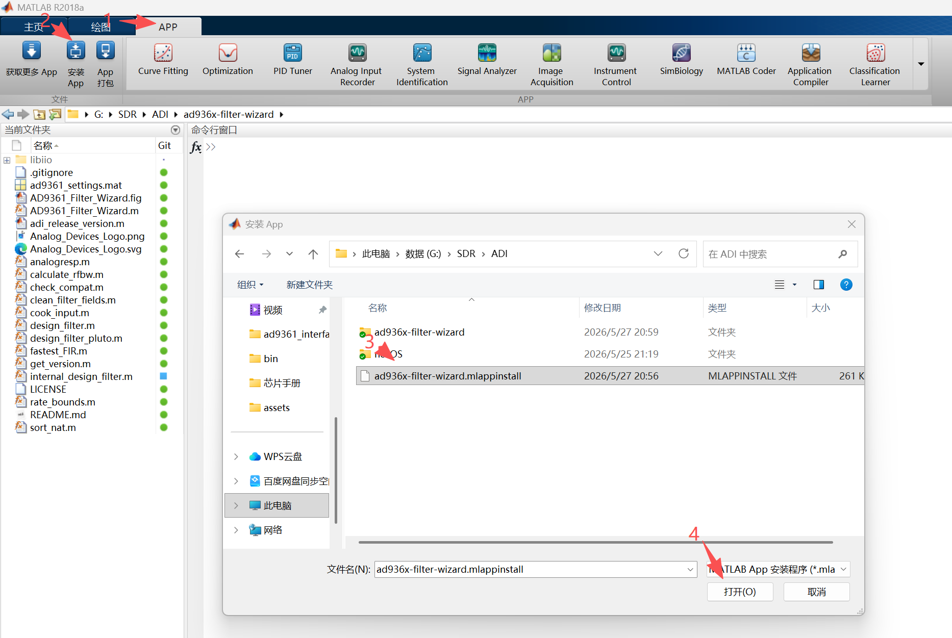
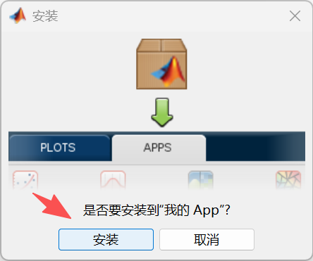
- 安装ad936x-filter-wizard.mlappinstall
- 安装完成后可通过如下步骤启动ad936x-filter-wizard
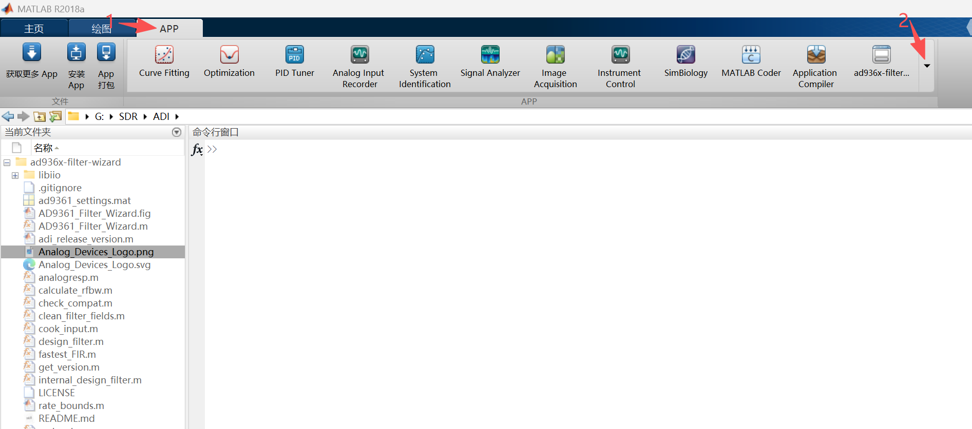
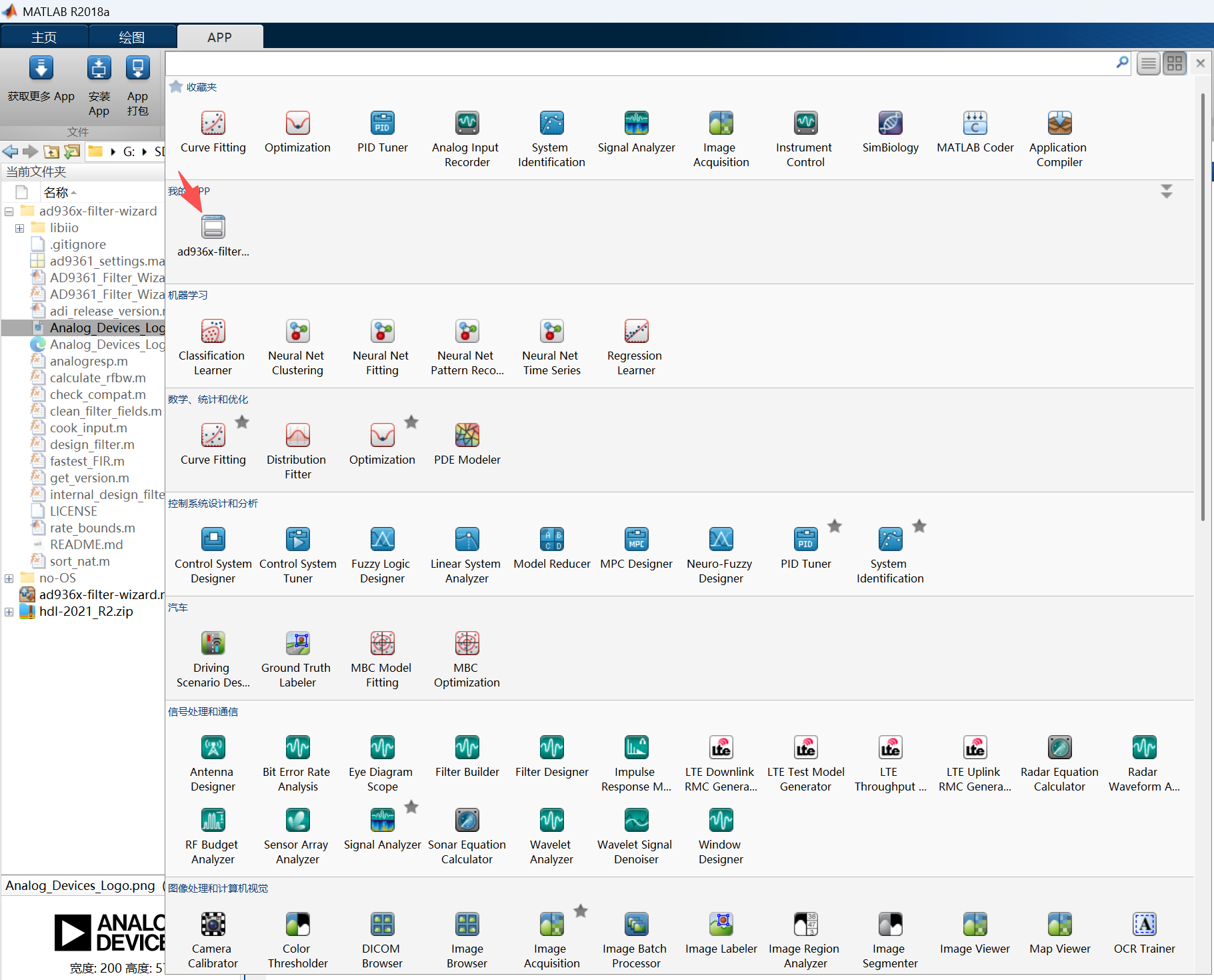
ad936x-filter-wizard的使用
有关ad936x-filter-wizard的使用可以参考ADI官方资料
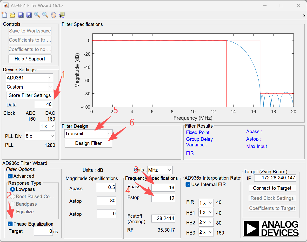
- Device Settings,用于选择设备和默认配置(若默认配置无法满足需求也可以自行配置)。
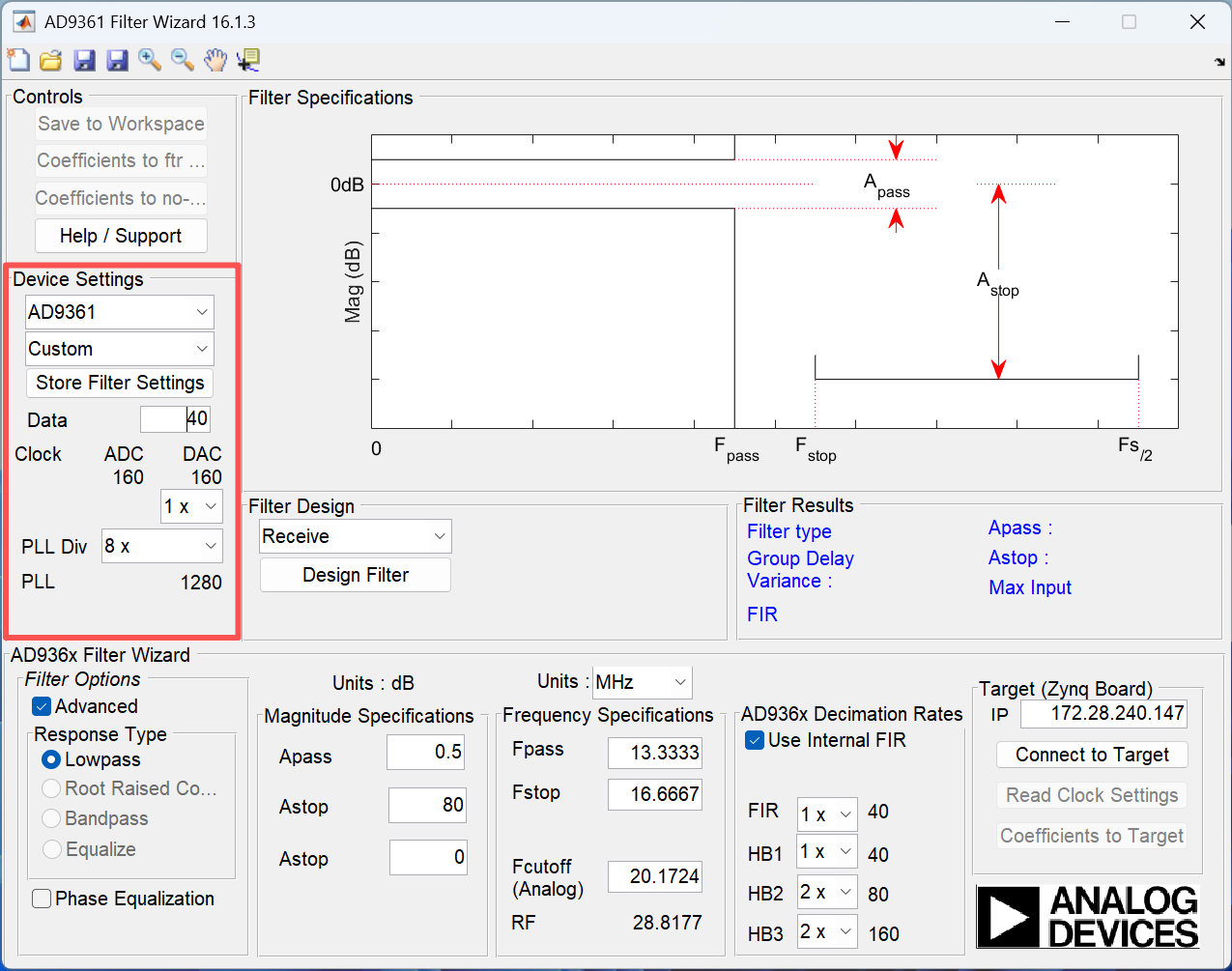
上面红框中从上往下依次是:
- 设备类型,可以选择AD9361和AD9364
- 默认配置,可以选择LTE5、LTE10、LTE15、LTE20,如果默认参数不满足需求可以直接再下面输入框输入数据,此时这里自动切换到Custom
- 保存自定义配置参数,只有在使用自定义参数时这个按钮才会出现
- 数据采样率,可以设置为0.52083~61.414
- 下面是时钟和PLL配置,会根据采样率自动调整,无需手动配置
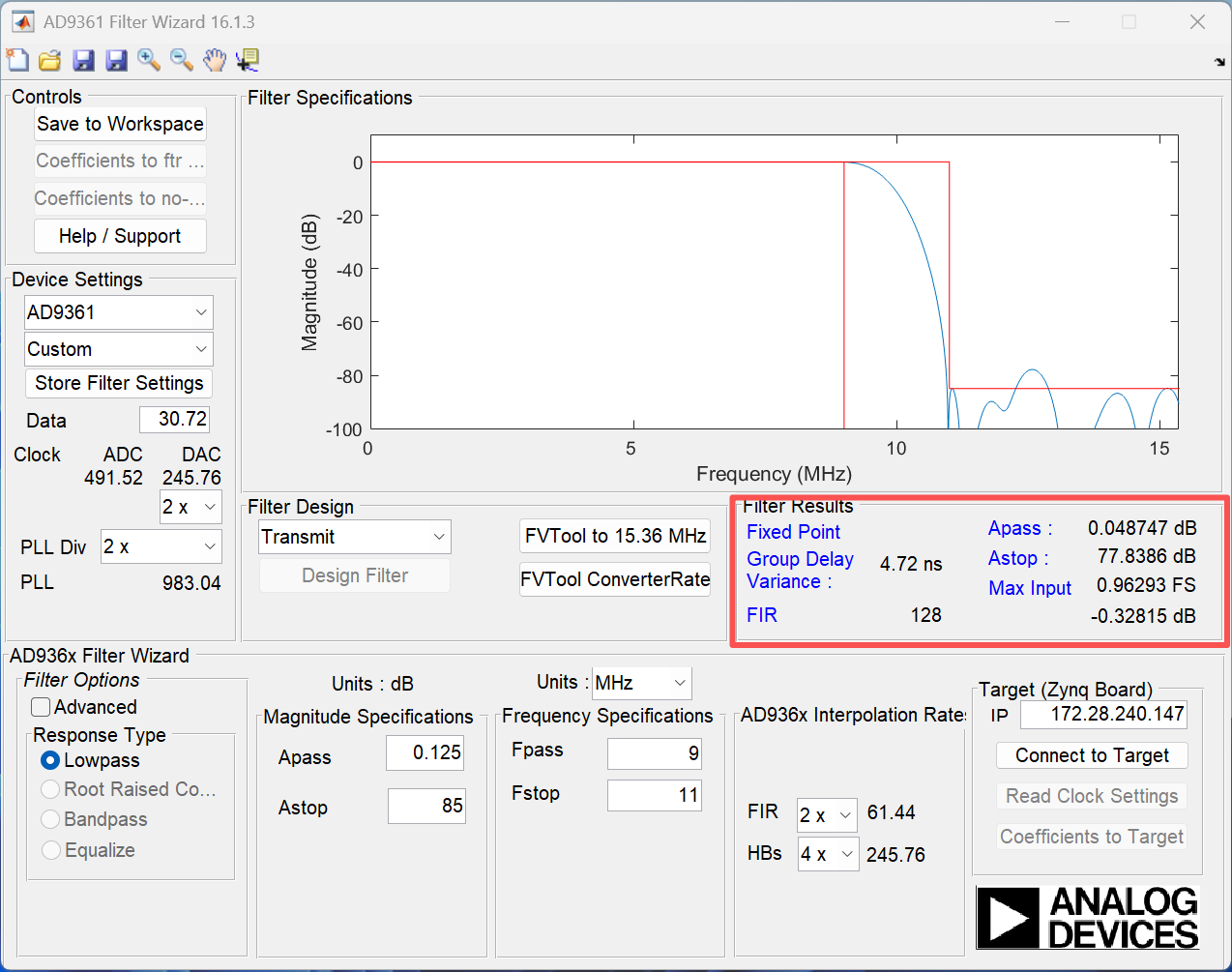
- magnitude specification,用于配通带平坦度和阻带衰减
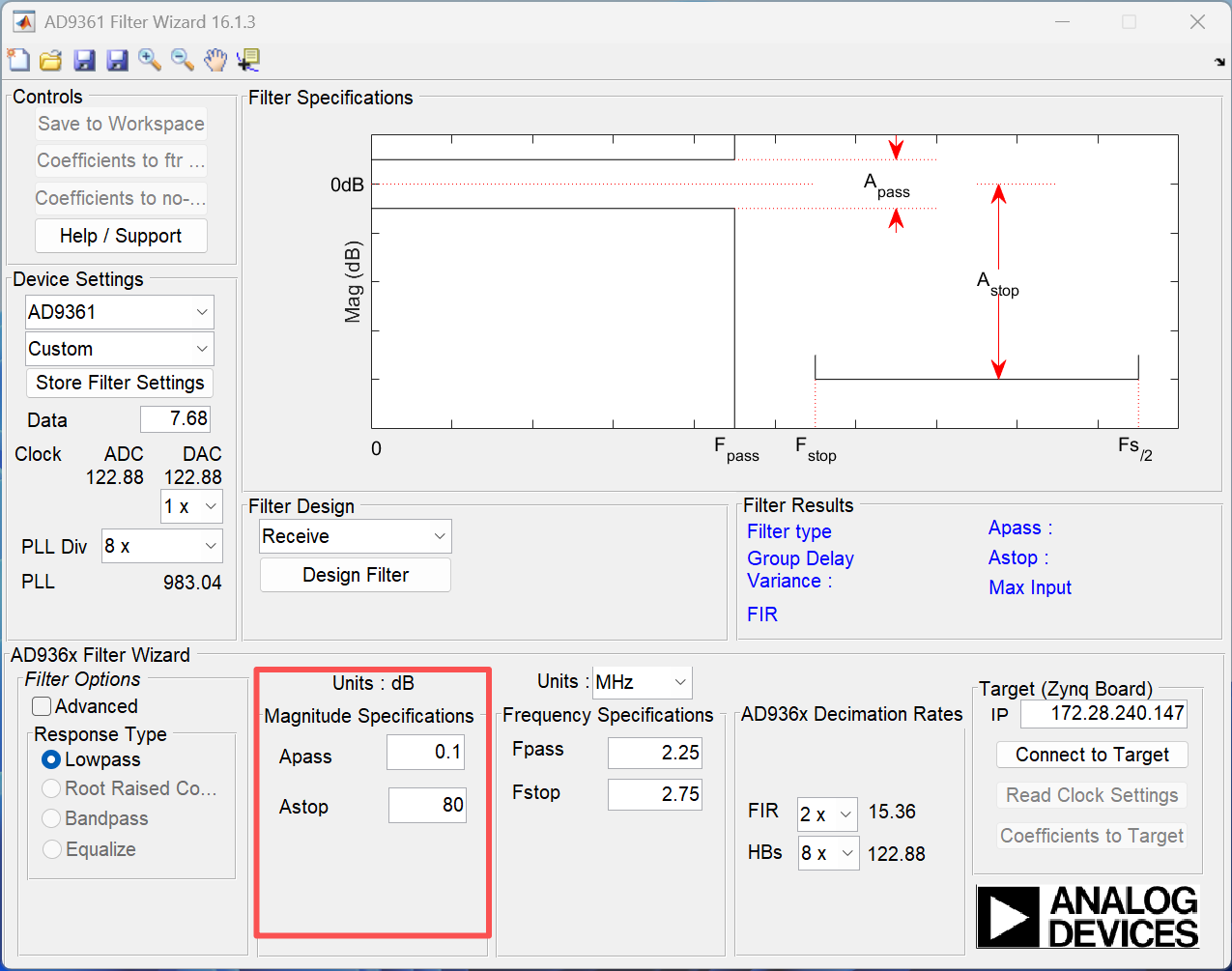
上面红框中从上往下依次是:
- Apass :通带平坦度
- Astop :阻带衰减
- frequency specifications,用于设置通带边界频率和阻带边界频率
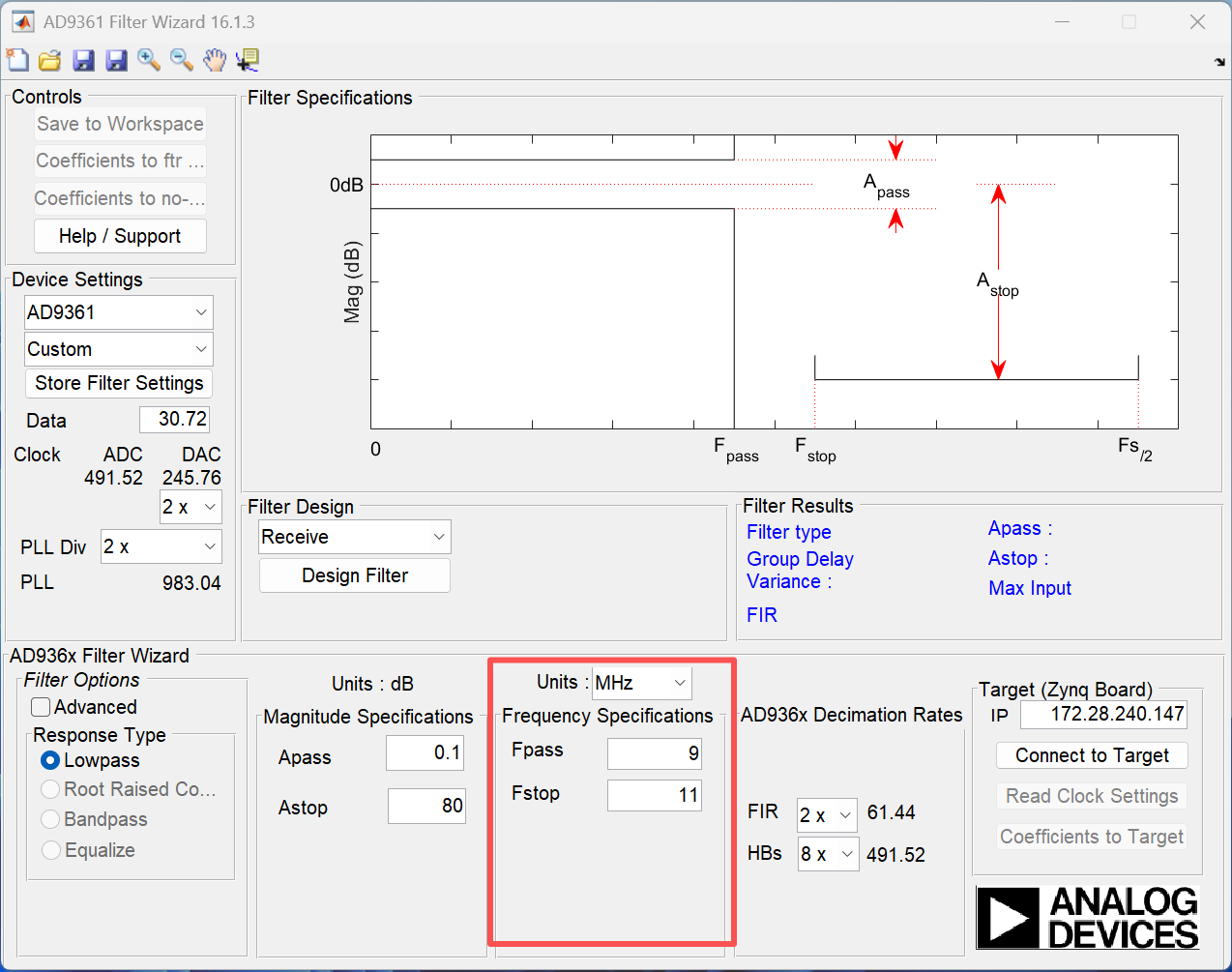 上面红框中从上往下依次是:
- Fpass :通带边界频率
- Fstop :阻带边界频率
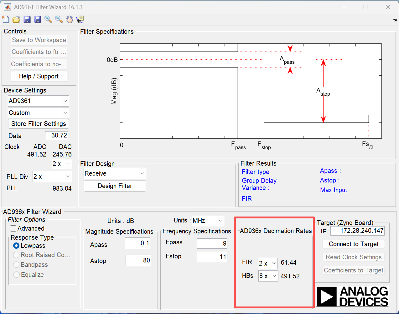
- AD936x Decimation Rate(接收)和AD936x Interpolation Rate(发射),用于设置滤波器抽取系(接收)和内插系数(发射),建议保持默认
- filter design,用于生成滤波器设计
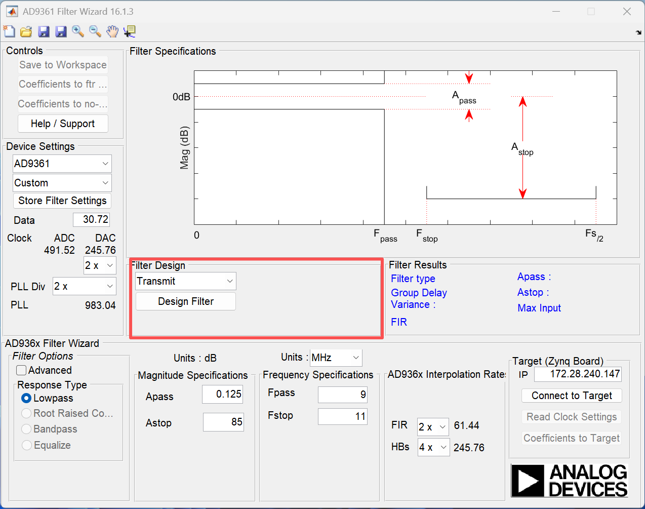 上面红框中从上往下依次是:
- 收发通道选择,可以选择接收或者发射
- 生成选择接收或者发射通道的滤波器参数
- filter results,显示生成滤波器的参数,如群延时,阶数等
- controls,保存生成的滤波器参数,其中保存为ftr和c需要将发射通道和接收通道的滤波器均生成好后才可用
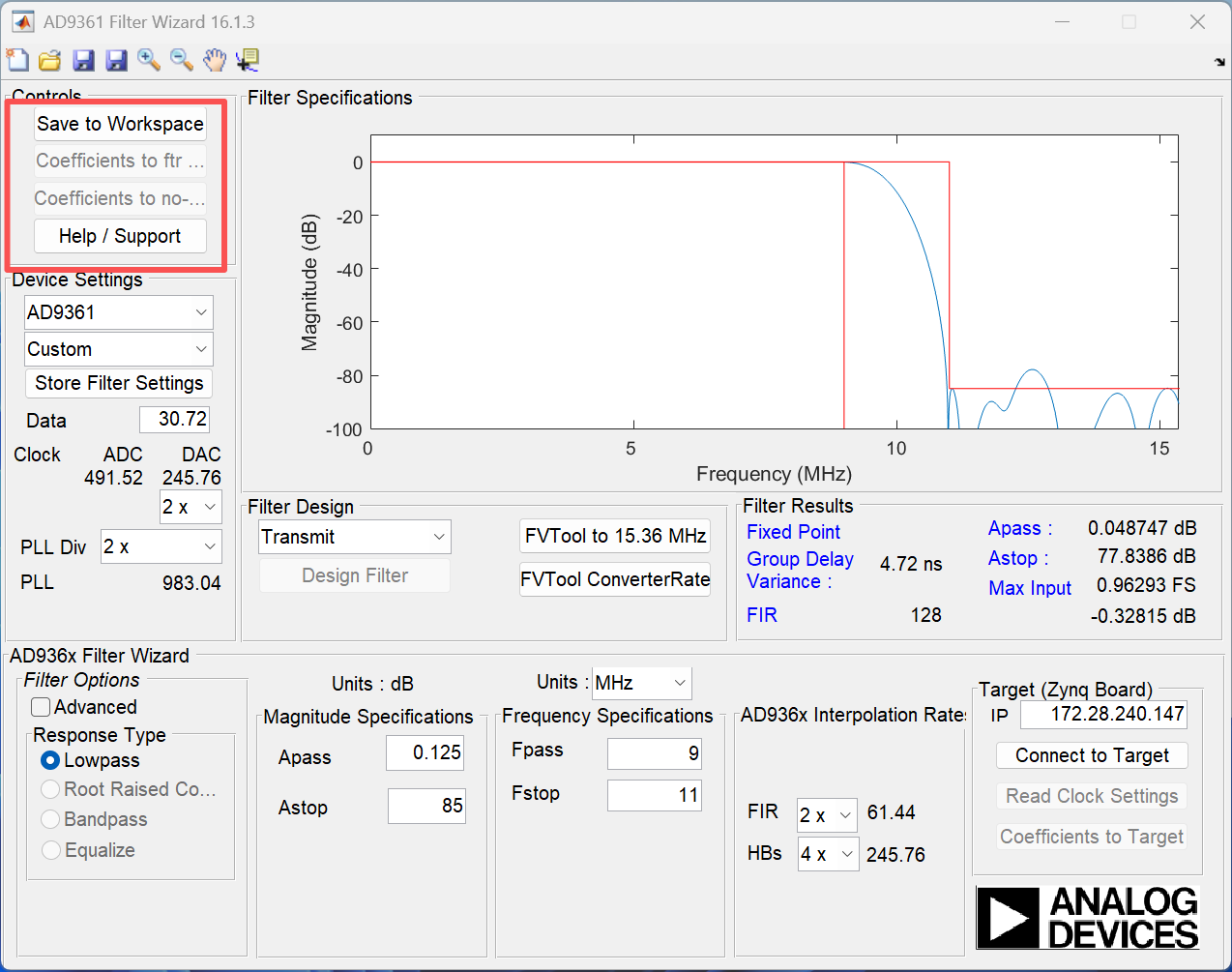
上面红框中从上往下依次是:
- 将滤波器参数保存到matlab工作空间
- 将滤波器参数保存为ftr文件
- 将滤波器参数保存为c文件
- 打开帮助页面
ad936x-filter-wizard的高级功能
勾选Advanced后会多出如下红框中的配置选项
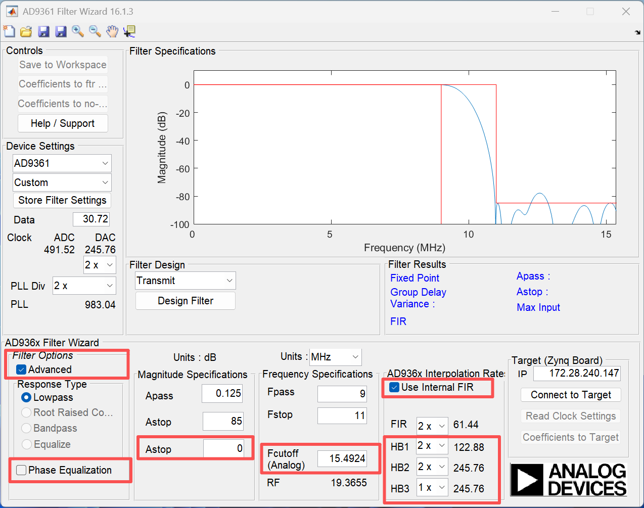
- Phase Equalization,如果您希望 FIR 滤波器进行相位均衡,可以启用"Phase Equalization"选项。相位均衡的主要目的是减少模拟滤波器、数字滤波器和 FIR 滤波器带来的通带群延迟方差,从而使不同频率的信号在经过滤波器链时,延迟量几乎相同。
- Astop,指定 FIR 滤波器(而非复合响应)的衰减,大多数情况下不需要此参数,因此您可以将其保留为 0。
- Fcutoff(Analog),指定模拟巴特沃斯滤波器的截止频率,默认情况下,应用程序会根据您输入的 Fpass 和 Fstop 值自动计算此参数,因此您可以保持默认设置。但是,如果您想进行调整,可以在此处输入一个数值。
- Use Internal FIR,由于功耗限制,部分用户可能不希望使用 AD936x 上的 FIR 滤波器,而是希望将 FIR 滤波器的实现移至 FPGA 或其他处理器上。如果不使用 AD936x 的 FIR 滤波器,可以关闭"Use Internal FIR"选项。
- HB1~HB3,半带滤波器的内插或抽取因子,一般保持默认即可。
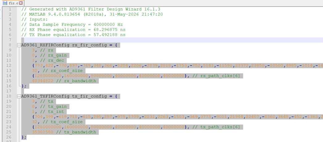
保存为C文件
-
生成发射通道的滤波器参数
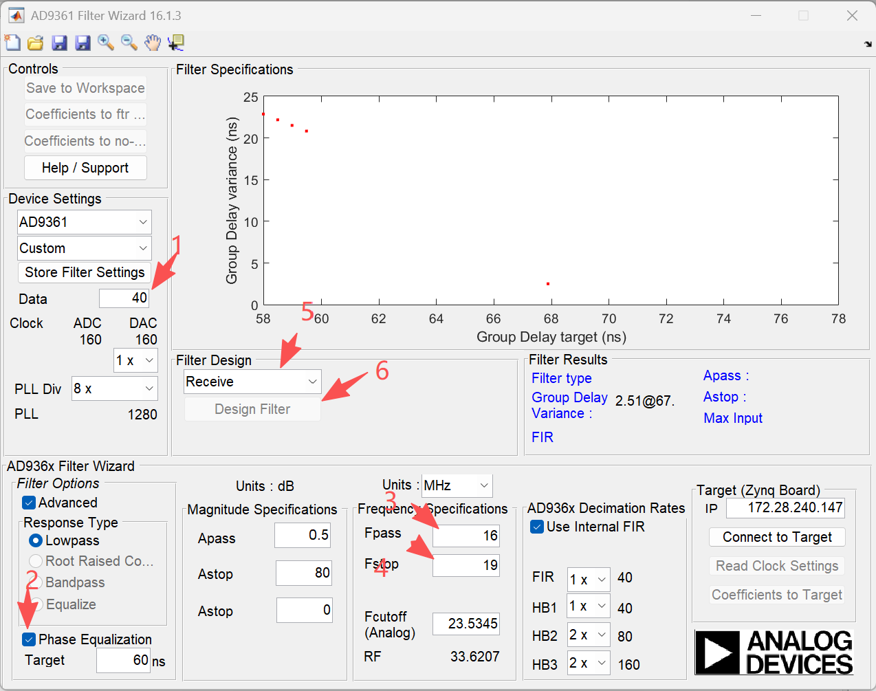
-
生成接收通道的滤波器参数
-
将参数存为C文件
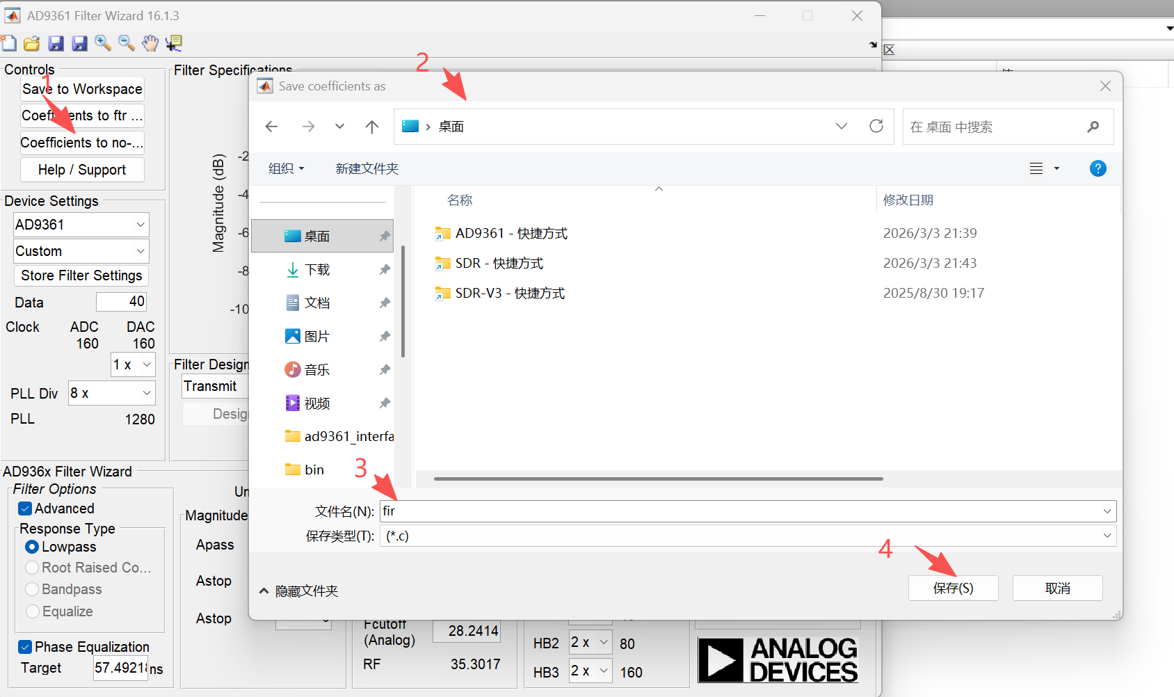
-
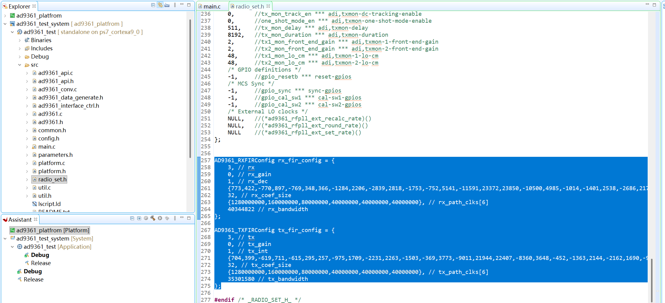
将C文件中"AD9361_RXFIRConfig rx_fir_config"和"AD9361_TXFIRConfig tx_fir_config"的变量拷贝到VITIS工程中,替换VITIS工程中的"AD9361_RXFIRConfig rx_fir_config"和"AD9361_TXFIRConfig tx_fir_config"变量,再AD9361初始化过程中会利用"AD9361_RXFIRConfig rx_fir_config"和"AD9361_TXFIRConfig tx_fir_config"变量配置AD9361的FIR滤波器。