文章目录
1.算法原理
相机传感器的光谱响应与人眼(或标准色彩空间 sRGB)不完全匹配,CCM 通过 3×3 线性变换将相机 RGB 转换到标准色彩空间,使得颜色更准确。
计算公式
实际上这里是,每个像素的RGB三通道的值,乘以一个比例系数,加上一个偏移.
[R_out]   [m00 m01 m02]   [R_in]   [m03]
[G_out] = [m10 m11 m12] × [G_in] + [m13]
[B_out]   [m20 m21 m22]   [B_in]   [m23]
在下面的测试例子里面所有系数为 1024 倍定点数(Q10 格式),最后除以 1024 还原浮点结果:
output = (M × input + offset) / 1024单位矩阵对应系数:对角线为 1024,其余为 0。
 1024     0      0
   0    1024     0
   0      0     1024
这里要说一下上面系数的给定,在openISP的测试数据中 ccm_00 ~ ccm_23 定义 3×4 矩阵,默认为单位变换(ccm_00=ccm_11=ccm_22=1024,其余为 0)。 为什么是3x4不是3x3,因为最后一个通道默认是偏移,结合后面测试代码看.
算法源代码
- 逐像素处理(for 循环),计算量 O(H×W),在大图上较慢
- 使用
uint32中间类型防止 3×255×1024 ≈ 786432 溢出 - 最终转换为
uint8(0~255)
python
class CCM:
    'Color Correction Matrix'

    def __init__(self, img, ccm):
        self.img = img
        self.ccm = ccm

    def execute(self):
        img_h = self.img.shape[0]
        img_w = self.img.shape[1]
        img_c = self.img.shape[2]
        ccm_img = np.empty((img_h, img_w, img_c), np.uint32)
        for y in range(img_h):
            for x in range(img_w):
                #下面会把ccm 中3x3的矩阵乘以后面RGB 3x1的矩阵,当前mulval还没有加offset
                mulval = self.ccm[:,0:3] * self.img[y,x,:]
                ccm_img[y,x,0] = np.sum(mulval[0]) + self.ccm[0,3] #加R通道偏移
                ccm_img[y,x,1] = np.sum(mulval[1]) + self.ccm[1,3] #加G通道偏移
                ccm_img[y,x,2] = np.sum(mulval[2]) + self.ccm[2,3] #加B通道偏移
                ccm_img[y,x,:] = ccm_img[y,x,:] / 1024 # Q格式转换,因为前面乘了1024
        self.img = ccm_img.astype(np.uint8)
        return self.img
2.测试代码
测试代码1-CCM对角矩阵
下面_identity_ccm函数生成了一个3x4的矩阵,前面3列是对角阵,第4列是offset,默认为0.
这里test_identity_matrix函数会生成一张RGB图,各分量分别为(r=100, g=150, b=80).
然后将系数矩阵传递CCM算法,由于这里没有offset,而且对角线上都是1024,所以前后颜色一致
 1024     0      0     0
   0    1024     0     0
0 0 1024 0 上面的第4列的offset值,在当前CCM中不直接参与矩阵运算.实际的硬件上,大都会参与矩阵运算,实际计算是R,G,B,1的转置参与计算.
python
def _identity_ccm(self):
"""返回等效单位变换的 3×4 CCM(系数×1024)。"""
ccm = np.zeros((3, 4))
ccm[0, 0] = 1024
ccm[1, 1] = 1024
ccm[2, 2] = 1024
return ccm
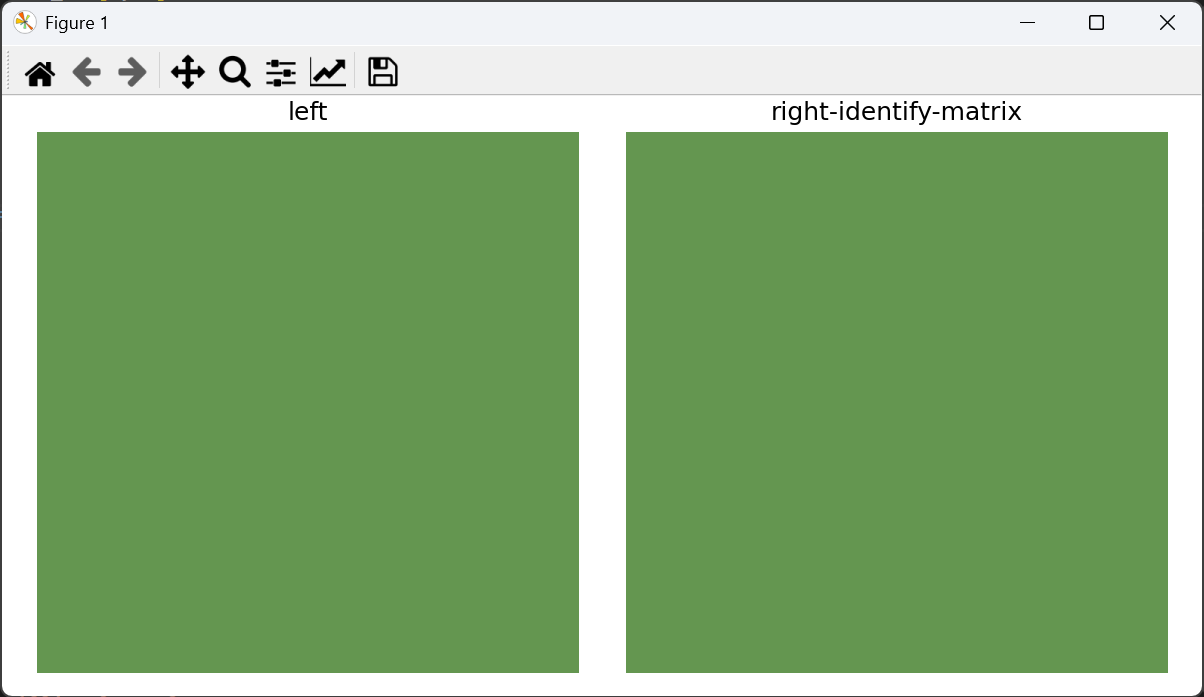
def test_identity_matrix(self):
"""单位 CCM 不应改变颜色(结果 = input / 1024 * 1024 = input,取整误差 ±1)。"""
img = make_rgb(8, 8, r=100, g=150, b=80)
ccm_mat = self._identity_ccm()
ccm = CCM(img.copy(), ccm_mat)
out = ccm.execute()
show_RGB_RGB_images(img, out, "left", "right-identify-matrix")- 效果图
这里由于对角线上加权系数都一样,且没有offset, 理论上做CCM前后,颜色基本是一样的.如下图所示
测试代码2-CCM+offset
这里_identity_ccm构建3x4矩阵,前面3x3是对角线矩阵,在函数内部会对R和G通道加一个偏移,改变通道颜色.
python
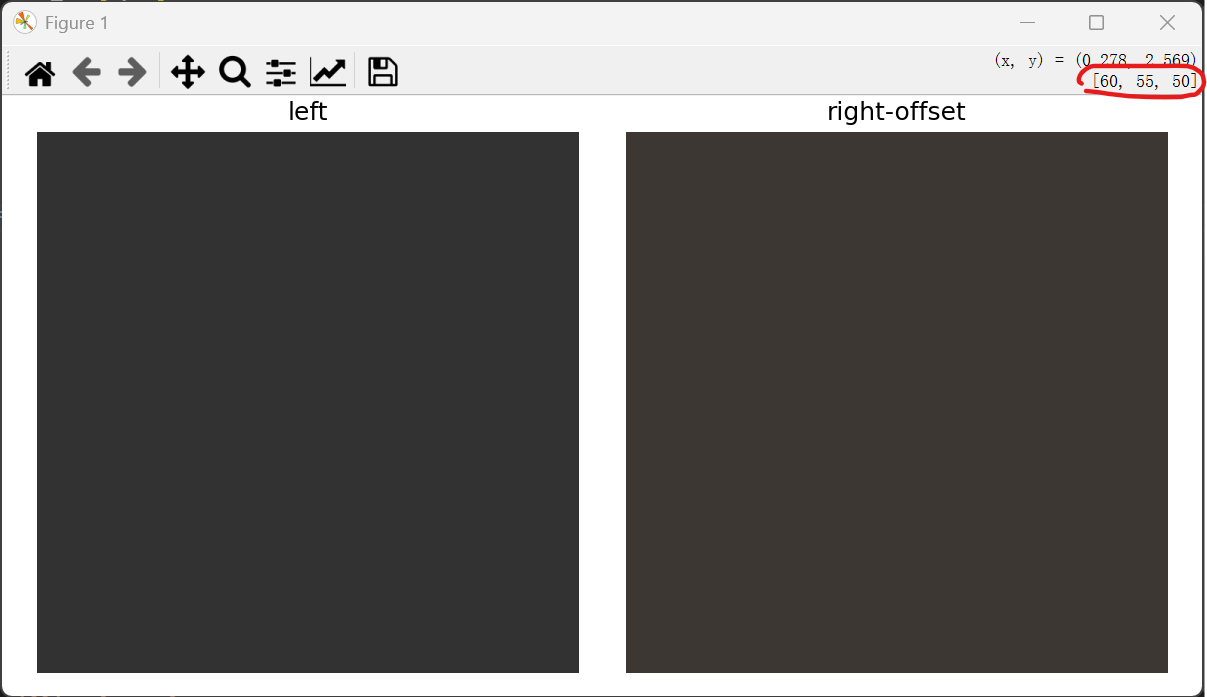
    def test_offset_applied(self):
        """CCM offset 项应加到每个通道上(offset[R]=10*1024,最终加 10)。"""
        img = make_rgb(4, 4, r=50, g=50, b=50)
        ccm_mat = self._identity_ccm()
        ccm_mat[0, 3] = 10 * 1024   # R 通道加 10
        ccm_mat[1, 3] = 5 * 1024    # G 通道加 5
        ccm_mat[2, 3] = 0
        ccm = CCM(img.copy(), ccm_mat)
        out = ccm.execute()
        show_RGB_RGB_images(img, out, "left", "right-offset")
        self.assertEqual(int(out[0, 0, 0]), 10)   # R = 0 + 10
        self.assertEqual(int(out[0, 0, 1]), 5)    # G = 0 + 5
self.assertEqual(int(out[0, 0, 2]), 0) # B = 0- 效果图
如上面的构建的RGB图像各分量为50,50,50,然后给R通道加了10,G通道加了5,如下图右上角框住区域,可看到颜色确实更改了.
测试代码3-改变通道的增益系数
ccm为 3x4的矩阵,其左侧的3x3为对角矩阵,如下所示.
    1024   0     0
    0    1024    0
0 0 1024由于测试代码中把1,0改成1024,1,1改成0,改后的3x3 CCM为下图左侧
    1024   0     0        [R_in]
    1024   0     0     x  [G_in]
    0      0    1024      [B_in]
根据矩阵运算后RGB的值
R_out = 1024 * R_in
G_out = 1024 * R_in + 0 * G_in
B_out = 1024 * B_in
从上面的矩阵运算能看到,G_out 不受 G_in 因为G_in的系数变成0了.
python
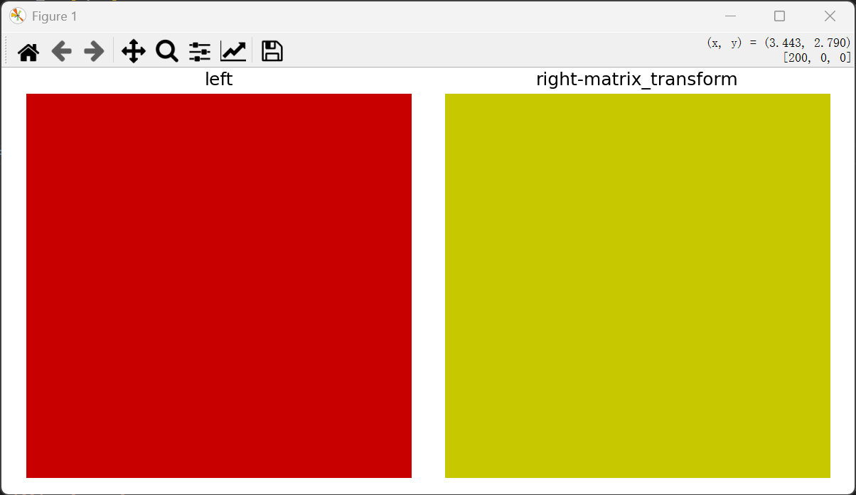
    def test_matrix_transform(self):
        """
        自定义 CCM(R→G 交叉项验证):
        ccm[1,0]=1024 → G_out = R_in,其余对角线为 1024,偏置为 0。
        输入 R=200, G=0, B=0 → 输出 R=200, G=200, B=0。
        """
        img = make_rgb(4, 4, r=200, g=0, b=0)
        ccm_mat = self._identity_ccm()
        ccm_mat[1, 0] = 1024   # G_out 也受 R_in 影响
        ccm_mat[1, 1] = 0      # G_out 不受 G_in 影响

        ccm = CCM(img.copy(), ccm_mat)
        out = ccm.execute()
show_RGB_RGB_images(img, out, "left", "right-matrix_transform")- 效果图
从代码中得知G通道不受G_in控制,颜色发生了变换.