- 1、傅里叶变换 + 霍夫变换+ 直线 + 角度 + 旋转
- 2、边缘检测 + 霍夫变换 + 直线+角度 + 旋转
- 3、四点透视 + 角度 + 旋转
- 4、检测矩形轮廓 + 角度 + 旋转
1.目的
实现类似全能扫面王的图像校正功能
2. 基于轮廓提取和透射变换
基于轮廓提取和透射变换的矫正算法更适用于车牌 、身份证 、人民币 、书本 、 发票一类矩形形状而且边界明显的物体矫正。所校正的内容必须要有清晰的完整轮廓。
基本步骤:
- 图片灰度化
- 二值化/canny边缘检测等操作
- 检测轮廓,并筛选出目标轮廓(通过横纵比或面积去除干扰轮廓)
- 获取图像顶点
- 透视变换
代码:
python
import cv2
import numpy as np

def contour_to_rect(contour):
    pts = contour.reshape(4, 2)
    print(pts)
    rect = np.zeros((4, 2), dtype = "float32")
    # top-left point has the smallest sum
    # bottom-right has the largest sum
    s = pts.sum(axis = 1)
#     print(s)
    rect[0] = pts[np.argmin(s)]
#     print(pts[np.argmin(s)])
    rect[2] = pts[np.argmax(s)]
    # compute the difference between the points:
    # the top-right will have the minumum difference
    # the bottom-left will have the maximum difference
    diff = np.diff(pts, axis = 1)
    rect[1] = pts[np.argmin(diff)]
    rect[3] = pts[np.argmax(diff)]
    return rect

# approximate the contour by a more primitive polygon shape
def approximate_contour(contour):
    peri = cv2.arcLength(contour, True)
    return cv2.approxPolyDP(contour, 0.032 * peri, True)

# 获取顶点坐标
def get_receipt_contour(contours):
    # loop over the contours
    for c in contours:
        approx = approximate_contour(c)
        # if our approximated contour has four points, we can assume it is receipt's rectangle
        if len(approx) == 4:
            return approx


def wrap_perspective(img, rect):
    # unpack rectangle points: top left, top right, bottom right, bottom left
    (tl, tr, br, bl) = rect
    # compute the width of the new image
    widthA = np.sqrt(((br[0] - bl[0]) ** 2) + ((br[1] - bl[1]) ** 2))
    widthB = np.sqrt(((tr[0] - tl[0]) ** 2) + ((tr[1] - tl[1]) ** 2))
    # compute the height of the new image
    heightA = np.sqrt(((tr[0] - br[0]) ** 2) + ((tr[1] - br[1]) ** 2))
    heightB = np.sqrt(((tl[0] - bl[0]) ** 2) + ((tl[1] - bl[1]) ** 2))
    # take the maximum of the width and height values to reach
    # our final dimensions
    maxWidth = max(int(widthA), int(widthB))
    maxHeight = max(int(heightA), int(heightB))
    # destination points which will be used to map the screen to a "scanned" view
    dst = np.array([
        [0, 0],
        [maxWidth - 1, 0],
        [maxWidth - 1, maxHeight - 1],
        [0, maxHeight - 1]], dtype = "float32")
    # calculate the perspective transform matrix
    M = cv2.getPerspectiveTransform(rect, dst)
    # warp the perspective to grab the screen
    return cv2.warpPerspective(img, M, (maxWidth, maxHeight))


if __name__ == "__main__":
    img = cv2.imread("./images/1.png")
    gray = cv2.cvtColor(img, cv2.COLOR_BGR2GRAY)
    # 用高斯滤波处理原图像降噪
    blur = cv2.GaussianBlur(gray, (5, 5), 0)
	#canny边缘检测(仅针对这次的输入图片)
    edged = cv2.Canny(blur, 50, 150)
    contours, h = cv2.findContours(edged.copy(), mode=cv2.RETR_EXTERNAL, method=cv2.CHAIN_APPROX_SIMPLE)
    # img_contours = cv2.drawContours(img.copy(), contours, -1, (0, 0, 255), 3)

    largest_contours = sorted(contours, key=cv2.contourArea, reverse=True)[:5]
    # img_largest_contours = cv2.drawContours( img.copy(), largest_contours, -1, (0, 0, 255), 3)

    receipt_contour = get_receipt_contour(largest_contours)
    # img_receipt_contour = cv2.drawContours(img.copy(), [receipt_contour], -1, (0, 0, 255), 3)

    ori_img = img.copy()
    for coor in contour_to_rect(receipt_contour):
        cv2.circle(ori_img, (int(coor[0]), int(coor[1])), 1, (0, 0, 255), 4)
	# 进行透视变换
    scanned = wrap_perspective(img.copy(), contour_to_rect(receipt_contour))
2.1 图像灰度化
gray = cv2.cvtColor(img, cv2.COLOR_BGR2GRAY)
blur = cv2.GaussianBlur(gray, (5, 5), 0)(如果有噪声可以加个高斯滤波)
2.2 canny边缘检测
edged = cv2.Canny(blur, 50, 150) (三个参数分别输入图像,最小阈值,最大阈值)
下图中左为输出,右为边缘检测结果。看起来效果还行

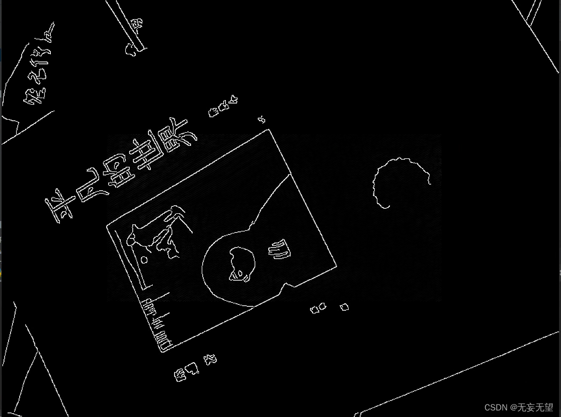
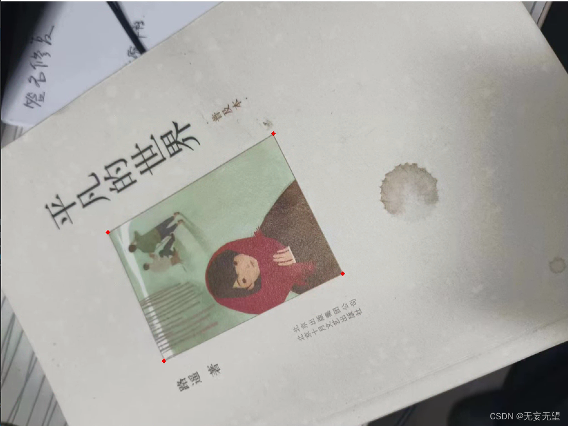
左为所有轮廓绘制,右为面积前五的绘制。可以看到,书中长方形的框并不在检测中,这是因为在进行边缘检测时色差不大导致没检测出来,后续使用闭运算处理将连断出填充完。
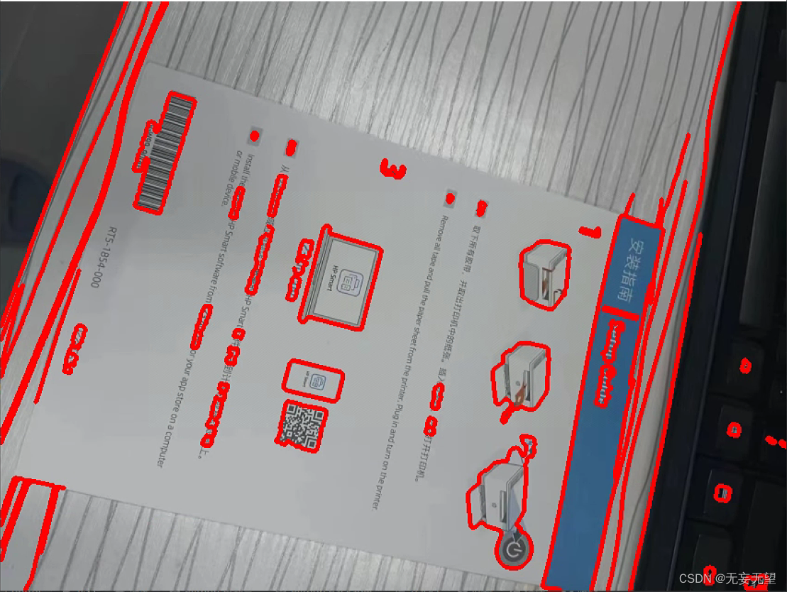
但是对于,图像边框,或者说前景与背景色差不大时,很难检测出来,如下图放在白色桌面的安装指南
2.3 检测轮廓,并筛选出目标轮廓(通过横纵比或面积去除干扰轮廓)
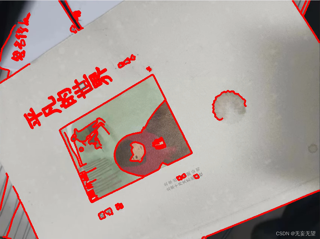
contours, h = cv2.findContours(edged.copy(), mode=cv2.RETR_EXTERNAL, method=cv2.CHAIN_APPROX_SIMPLE)
img_contours = cv2.drawContours(img.copy(), contours, -1, (0, 0, 255), 3)
检测图像轮廓并绘制所有的轮廓
approximate the contour by a more primitive polygon shape
def approximate_contour(contour):
peri = cv2.arcLength(contour, True)
return cv2.approxPolyDP(contour, 0.032 * peri, True)
获取顶点坐标
def get_receipt_contour(contours):
loop over the contours
for c in contours:
approx = approximate_contour(c)
if our approximated contour has four points, we can assume it is receipt's rectangle
if len(approx) == 4:
return approx
在这个实现中,
approximate_contour函数使用cv2.approxPolyDP来近似轮廓。cv2.approxPolyDP的第二个参数是精度参数,它是一个距离值,表示近似轮廓与原始轮廓之间的最大距离。这个值是原始轮廓周长的百分比,通常设置为一个很小的值(例如0.02)。第三个参数True表示近似出的多边形是闭合的。
get_receipt_contour函数然后使用这个近似函数来寻找一个四边形的轮廓,假设这个四边形是收据的形状。如果找到了一个有四个顶点的轮廓,它就返回这个轮廓。如果没有找到,函数将返回None。请注意,这个函数假设收据是一个四边形,并且是轮廓列表中面积最大的四边形。在实际应用中,可能需要根据收据的具体形状和图像中的其他元素来调整这个函数。
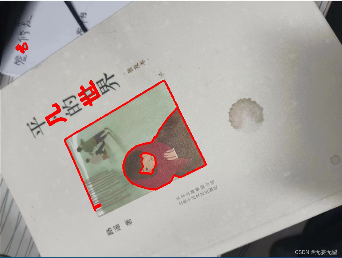
2.4 获取图像顶点
receipt_contour = get_receipt_contour(largest_contours)
img_receipt_contour = cv2.drawContours(img.copy(), receipt_contour, -1, (0, 0, 255), 3)
def contour_to_rect(contour):
pts = contour.reshape(4, 2)
print(pts)
rect = np.zeros((4, 2), dtype = "float32")
top-left point has the smallest sum
bottom-right has the largest sum
s = pts.sum(axis = 1)
print(s)
rect0 = ptsnp.argmin(s)
print(ptsnp.argmin(s))
rect2 = ptsnp.argmax(s)
compute the difference between the points:
the top-right will have the minumum difference
the bottom-left will have the maximum difference
diff = np.diff(pts, axis = 1)
rect1 = ptsnp.argmin(diff)
rect3 = ptsnp.argmax(diff)
return rect
在您提供的
contour_to_rect函数中,目标是将以四个顶点形式给出的轮廓转换为一个矩形,这个矩形以特定的顺序排列顶点,通常是顺时针或逆时针方向,从左上角开始。然而,在您提供的代码中存在一些问题,包括一个拼写错误和一个可能的逻辑错误。我将为您纠正这些问题,并提供一个完整的函数,该函数将返回一个按正确顺序排列顶点的矩形。
ori_img = img.copy() for coor in contour_to_rect(receipt_contour): cv2.circle(ori_img, (int(coor0), int(coor1)), 1, (0, 0, 255), 4)将筛选的四个点在图像中标注
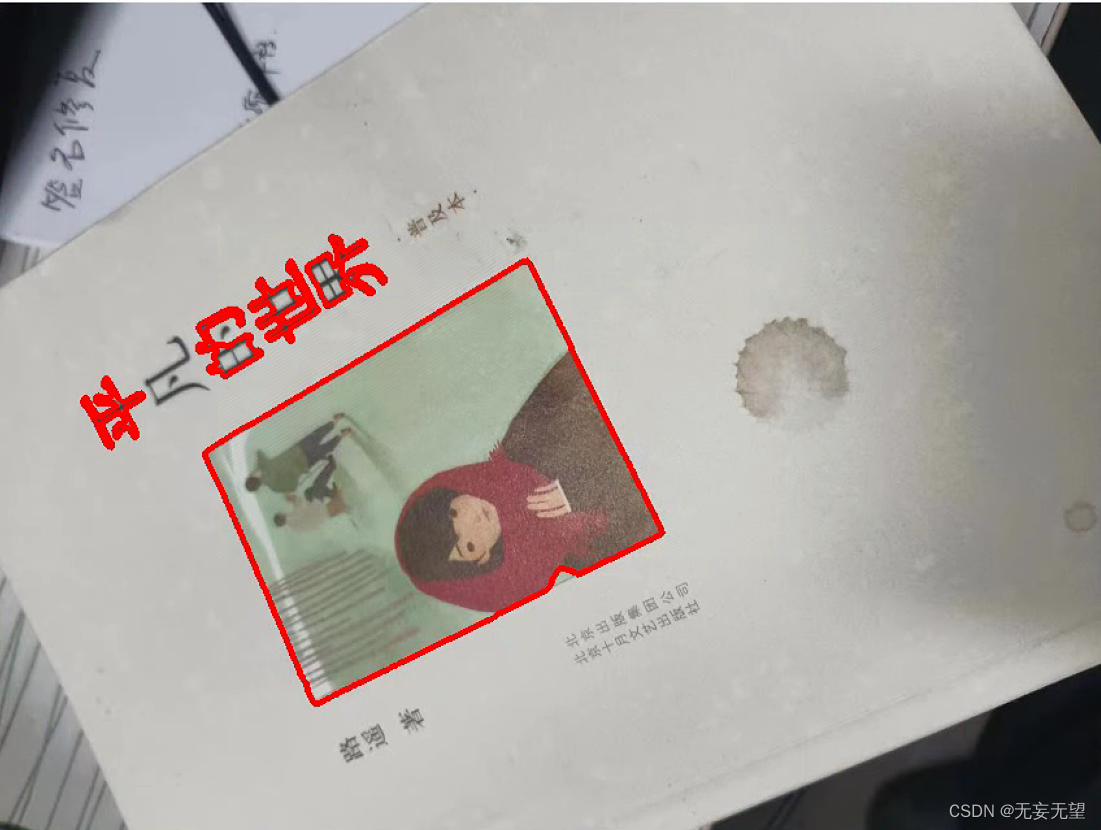
2.5 透视变换
scanned = wrap_perspective(img.copy(), contour_to_rect(receipt_contour))
def wrap_perspective(img, rect):
    # unpack rectangle points: top left, top right, bottom right, bottom left
    (tl, tr, br, bl) = rect
    # compute the width of the new image
    widthA = np.sqrt(((br[0] - bl[0]) ** 2) + ((br[1] - bl[1]) ** 2))
    widthB = np.sqrt(((tr[0] - tl[0]) ** 2) + ((tr[1] - tl[1]) ** 2))
    # compute the height of the new image
    heightA = np.sqrt(((tr[0] - br[0]) ** 2) + ((tr[1] - br[1]) ** 2))
    heightB = np.sqrt(((tl[0] - bl[0]) ** 2) + ((tl[1] - bl[1]) ** 2))
    # take the maximum of the width and height values to reach
    # our final dimensions
    maxWidth = max(int(widthA), int(widthB))
    maxHeight = max(int(heightA), int(heightB))
    # destination points which will be used to map the screen to a "scanned" view
    dst = np.array([
        [0, 0],
        [maxWidth - 1, 0],
        [maxWidth - 1, maxHeight - 1],
        [0, maxHeight - 1]], dtype = "float32")
    # calculate the perspective transform matrix
    M = cv2.getPerspectiveTransform(rect, dst)
    # warp the perspective to grab the screen
    return cv2.warpPerspective(img, M, (maxWidth, maxHeight))
您提供的
wrap_perspective函数是用于执行透视变换的,这种变换通常用于将图像中的四边形区域(如收据、文档等)转换为俯视图,即"扫描"视图。这个函数接受两个参数:要变换的图像img和一个表示四边形顶点的numpy数组rect。以下是函数中每一步的解释:
解包四边形顶点 :将四边形的顶点解包为
tl(左上角)、tr(右上角)、br(右下角)和bl(左下角)。计算新图像的宽度 :通过计算对角线
br到bl和tr到tl的距离来得到新图像的潜在宽度。使用欧几里得距离公式sqrt((x2 - x1)^2 + (y2 - y1)^2)。计算新图像的高度 :同样,通过计算对角线
tr到br和tl到bl的距离来得到新图像的潜在高度。确定最终尺寸:通过取宽度 和高度的最大值来确保四边形在变换后不会被裁剪。
定义目标点 :创建一个目标点数组
dst,这些点定义了变换后的四边形的顶点位置。这些点将图像映射到一个矩形的"扫描"视图。计算透视变换矩阵 :使用
cv2.getPerspectiveTransform函数计算从原始四边形到目标矩形的透视变换矩阵M。执行透视变换 :使用
cv2.warpPerspective函数应用透视变换到图像img上,得到变换后的图像。
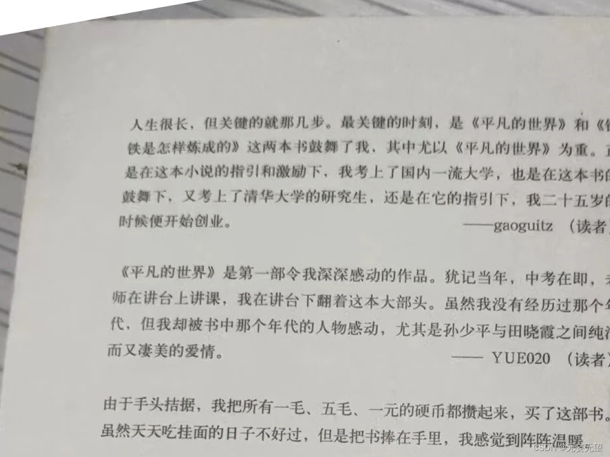
3. 基于霍夫直线探测和仿射变换
基于霍夫直线探测的矫正算法更适用于文本类等无明显边界图像的矫正。图像画面必须要干净
算法步骤
- 用霍夫线变换探测出图像中的所有直线。
- 计算出每条直线的倾斜角,求他们的平均值。
- 根据倾斜角旋转矫正。
- 最后根据文本尺寸裁剪图片。
代码:
python
import cv2
import numpy as np


img = cv2.imread("./images/4.jpg")
src = img.copy()
gray = cv2.cvtColor(src, cv2.COLOR_RGB2GRAY);
edged = cv2.Canny(src, 50, 200, apertureSize=3);

# 第5个参数就是阈值,阈值越大,检测精度越高
plines = cv2.HoughLines(edged, 1, np.pi / 180, 200);
if plines is not None:
    plines = plines.reshape(-1, 2)
    print(len(plines), "lines detected")

    sum_theta = 0.0
    for rho, theta in plines:
        # rho, theta = line[0]
        a = np.cos(theta)
        b = np.sin(theta)
        x0 = a * rho
        y0 = b * rho
        x1 = int(x0 + 1000*(-b))
        y1 = int(y0 + 1000*(a))
        x2 = int(x0 - 1000*(-b))
        y2 = int(y0 - 1000*(a))
        sum_theta += theta
        # 绘制直线
        cv2.line(src, (x1, y1), (x2, y2), (0, 0, 255), 2)

# 计算平均角度
average_theta = sum_theta / len(plines)
angle = np.degrees(average_theta) - 90

# 计算旋转中心
center = (float(img.shape[1] / 2.0), float(img.shape[0] / 2.0))
# 计算对角线长度作为旋转后图像的尺寸
length = int(np.sqrt(img.shape[0]**2 + img.shape[1]**2))
# 计算旋转矩阵
M = cv2.getRotationMatrix2D(center, angle, 1)
# 进行仿射变换并填充背景色为白色
src_rotate = cv2.warpAffine(img, M, (length, length), borderValue=(255, 255, 255))
3.1 图像预处理
在此不赘述,根据实际情况来
3.2 霍夫线变换
第5个参数就是阈值,阈值越大,检测精度越高
plines = cv2.HoughLines(edged, 1, np.pi / 180, 200);
在OpenCV中,
cv2.HoughLines函数用于检测图像中的直线。它使用霍夫变换(Hough Transform)来找到图像中直线的参数,然后将这些参数转换为图像中的直线。您提供的代码片段
plines = cv2.HoughLines(edged, 1, np.pi / 180, 200);是使用霍夫变换在经过Canny边缘检测的图像edged中检测直线的例子。这里的参数解释如下:
edged:这是已经通过Canny边缘检测得到的图像。1:这是霍夫变换中使用的rho(极径)参数。它定义了检测直线时的搜索范围。较大的值会使检测到的直线更加稀疏,而较小的值则可能导致检测到的直线更加密集。np.pi / 180:这是霍夫变换中使用的theta(角度)参数。它定义了检测直线时的角度范围。这里使用的是单位圆上的角度,即0到π弧度。200:这是霍夫变换中使用的阈值参数。它定义了直线检测的灵敏度。较大的值会使检测到的直线更加稀疏,而较小的值则可能导致检测到的直线更加密集。if plines is not None:
plines = plines.reshape(-1, 2)
print(len(plines), "lines detected")
在OpenCV中,
cv2.HoughLines函数返回一个包含检测到的直线的数组,如果没有任何直线被检测到,这个数组将为None。这种情况可能发生在以下几种情况下:
图像噪声:如果图像中的噪声非常强烈,可能会导致无法检测到任何直线。
参数设置 :
cv2.HoughLines函数的参数设置(如阈值、角度范围等)可能不适合当前图像。如果参数设置不当,可能无法检测到任何直线。图像内容:如果图像中没有明显的直线结构,例如在复杂的自然场景中,可能会检测不到直线。
图像大小:如果图像非常小,可能没有足够的空间来检测直线。
图像分辨率:如果图像的分辨率非常低,可能会导致检测到的直线不够精确。
图像方向:如果图像的方向与霍夫变换的搜索方向不匹配,可能会检测不到直线。
在实际应用中,您可能需要根据图像的具体内容和噪声水平来调整
cv2.HoughLines函数的参数,以提高检测直线的效果。
sum_theta = 0.0for rho, theta in plines:
rho, theta = line0
a = np.cos(theta)
b = np.sin(theta)
x0 = a * rho
y0 = b * rho
x1 = int(x0 + 1000*(-b))
y1 = int(y0 + 1000*(a))
x2 = int(x0 - 1000*(-b))
y2 = int(y0 - 1000*(a))
sum_theta += theta
绘制直线
cv2.line(src, (x1, y1), (x2, y2), (0, 0, 255), 2)
在您提供的代码片段中,您正在遍历通过霍夫变换检测到的直线,并将这些直线绘制在原始图像
src上。每个直线由两个点定义,这两个点是根据极径rho和角度theta计算出来的。代码中的关键步骤如下:
遍历
plines数组,其中每个元素是一个包含两个值rho和theta的元组。rho是直线与原点之间的距离,而theta是从x轴正向到直线方向的角度(以弧度为单位)。对于每个元素,您首先提取
rho和theta值。使用
np.cos(theta)和np.sin(theta)计算直线斜率a和b。使用
a * rho和b * rho计算直线上的两个点的x和y坐标。这些坐标是通过将rho值乘以直线的方向向量(由a和b定义)得到的。使用
int(x0 + 1000*(-b))和int(y0 + 1000*(a))计算第一个点的坐标,其中1000是一个常数,用于确保坐标在图像范围内。使用
int(x0 - 1000*(-b))和int(y0 - 1000*(a))计算第二个点的坐标。使用
cv2.line函数在原始图像src上绘制从第一个点到第二个点的直线,颜色为红色,线宽为2。将角度
theta累加到变量sum_theta中。
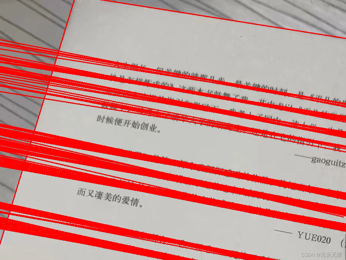
经过自己的多次实验,发现霍夫线变换的弧度转化为角度时,是以Y轴正半轴为0°,顺时针计算角度。并且在仿射变换进行旋转时,如果给的是正数,就会逆时针旋转,如果给的是负数,就会顺时针旋转
3.3 旋转角度和旋转中心
计算平均角度
average_theta = sum_theta / len(plines)
angle = np.degrees(average_theta) - 90
在OpenCV中,
cv2.HoughLines函数返回的角度参数是以弧度为单位的。这个函数使用霍夫变换来检测图像中的直线,而霍夫变换中使用的角度参数是弧度制的。霍夫变换是一种在图像中检测直线的方法,它将图像中的每个点转换为一个参数空间中的一个点,其中参数空间是一个笛卡尔坐标系,x轴和y轴分别对应于图像中的直线的斜率和截距。在霍夫变换中,θ是直线的倾斜角,以弧度为单位。
因此,当您从
cv2.HoughLines函数中获取θ值时,这些值是以弧度为单位的。如果您需要将它们转换为角度,可以使用NumPy的np.degrees函数来进行转换。请注意,弧度与度的转换关系是:
1 弧度=180 /Π 度
计算旋转中心
center = (float(img.shape1 / 2.0), float(img.shape0 / 2.0))
计算对角线长度作为旋转后图像的尺寸
length = int(np.sqrt(img.shape0**2 + img.shape1**2))
3.4 旋转矩阵
计算旋转矩阵
M = cv2.getRotationMatrix2D(center, angle, 1)
3.5 仿射变换
进行仿射变换并填充背景色为白色
src_rotate = cv2.warpAffine(img, M, (length, length), borderValue=(255, 255, 255))
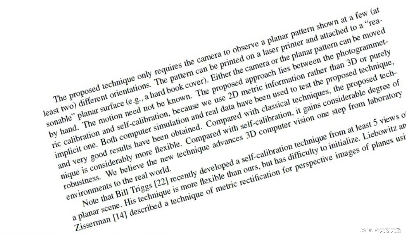
4. 基于最小外接矩形和仿射变换
有明显的单一外接矩形的图像,最好是文本。
算法步骤:
- 灰度化以及预处理
- 二值化/边缘检测
- 最小外接矩形
- 旋转中心、旋转角度以及旋转矩阵
- 仿射变换
代码:
python
import numpy as np
import cv2 as cv
def binary(img):
gray=cv.cvtColor(img,cv.COLOR_BGR2GRAY)
ret,binary = cv.threshold(gray,0,255,cv.THRESH_BINARY_INV|cv.THRESH_OTSU)
return binary
def Transformation(img,src):
coords=np.column_stack(np.where(img>0))
print(coords)
print(coords.shape)
angle =cv.minAreaRect(coords)[-1] #最小外接矩形
print(angle)
if angle<-45:
angle = -(90+angle)
else:
angle=-angle
center = (w//2,h//2)
M= cv.getRotationMatrix2D(center,angle,1.0) #传入中心和角度 得到旋转矩形
rotated = cv.warpAffine(src,M,(w,h),flags=cv.INTER_CUBIC,borderMode=cv.BORDER_REPLICATE)
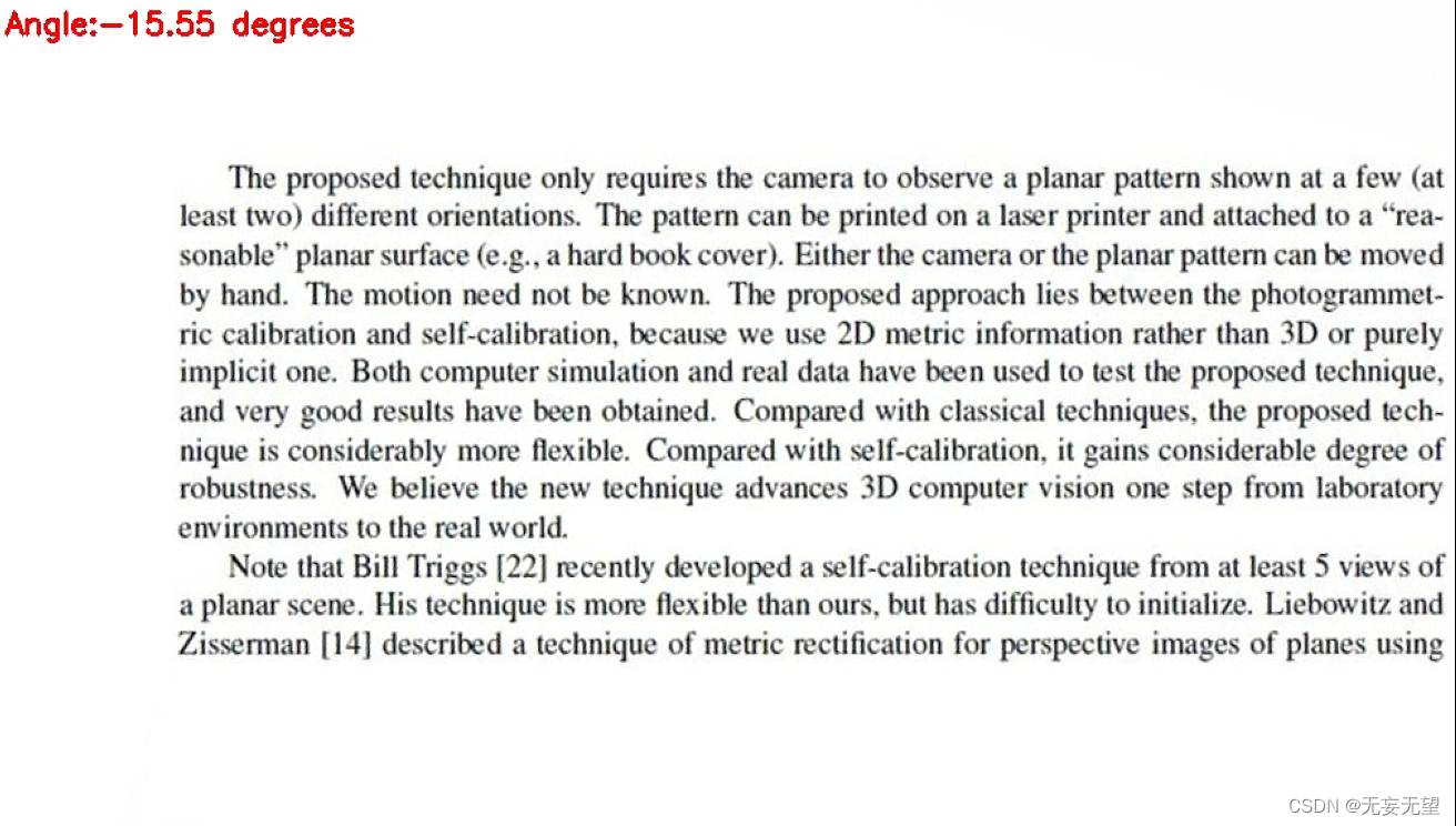
cv.putText(rotated,'Angle:{:.2f} degrees'.format(angle),(10,30),cv.FONT_HERSHEY_SIMPLEX,0.7,(0,0,255),2)#绘制文字
cv.imshow('Rotated',rotated)
src= cv.imread('imageTextR.png')
(h,w)=src.shape[:2]
gray=cv.cvtColor(src,cv.COLOR_BGR2GRAY)
binary=binary(src)
Transformation(binary,src)
cv.imshow('src',src)
cv.imshow('binary',binary)
cv.waitKey(0)4.1 灰度化以及预处理
不多赘述
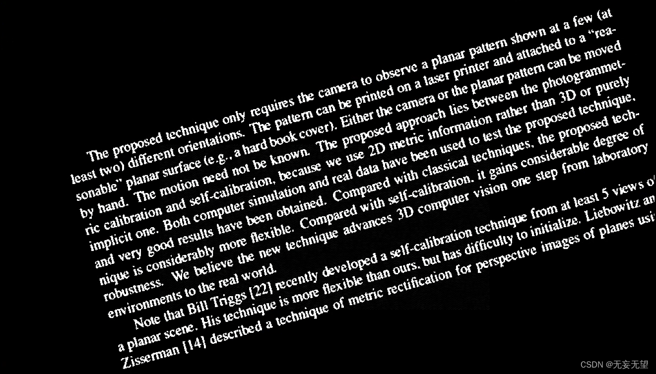
4.2 二值化
ret,binary = cv.threshold(gray,0,255,cv.THRESH_BINARY_INV|cv.THRESH_OTSU)在OpenCV中,
cv2.threshold函数用于将图像转换为二值图像。您提供的代码片段ret, binary = cv2.threshold(gray, 0, 255, cv2.THRESH_BINARY_INV | cv2.THRESH_OTSU)是使用cv2.threshold函数对灰度图像gray进行阈值处理,以创建一个二值图像binary。这里的参数解释如下:
gray:这是您要进行阈值处理的灰度图像。0:这是阈值处理的下限值。所有小于这个值的像素将被设置为0(通常是黑色)。255:这是阈值处理的上限值。所有大于这个值的像素将被设置为255(通常是白色)。cv2.THRESH_BINARY_INV | cv2.THRESH_OTSU:这是阈值处理的方法。cv2.THRESH_BINARY_INV表示使用二值反转阈值,即小于阈值的像素将被设置为255(白色),大于阈值的像素将被设置为0(黑色)。cv2.THRESH_OTSU表示使用Otsu's方法来自动选择阈值。Otsu's方法是一种自动选择阈值的方法,它通过最大化类间方差来选择最佳阈值。这种方法通常用于图像分割,以区分前景和背景。
4.3 最小外接矩形
首先获取所有非零坐标元素
coords=np.column_stack(np.where(binary>0))
在您提供的代码片段中,
coords = np.column_stack(np.where(binary > 0))是一个用于获取二值图像中所有非零像素位置的坐标的方法。具体步骤如下:
创建二值图像 :首先,您使用
cv2.threshold函数创建了一个二值图像binary。在这个二值图像中,值为0的像素代表背景,而值为255的像素代表前景。使用
np.where获取非零像素位置 :np.where(binary > 0)是一个NumPy函数,用于获取二值图像中所有非零像素的位置。这个函数返回一个包含所有非零像素坐标的元组,其中第一个元素是x坐标,第二个元素是y坐标。将坐标堆叠为列向量 :使用
np.column_stack函数将坐标堆叠为列向量。这个操作将创建一个二维数组,其中每一行代表一个像素点的坐标。
然后寻找最小外接矩形
angle =cv.minAreaRect(coords)-1
在OpenCV中,
cv2.minAreaRect函数用于找到图像中最小的外接矩形,并返回该矩形的旋转角度。这个函数通常用于对象检测和图像识别任务中。
cv2.minAreaRect函数的参数是一个包含像素点的坐标数组,这些点定义了一个多边形。函数返回的参数有三个:1.矩形的中心点 2.矩形的长和宽 3.矩形的旋转角度在您提供的代码片段中,
angle = cv2.minAreaRect(coords)[-1]的目的是获取最小外接矩形的旋转角度。coords是一个包含像素点的坐标数组,这些点定义了一个多边形,即您之前通过np.column_stack(np.where(binary > 0))获取的非零像素位置。
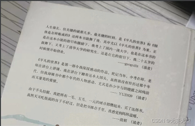
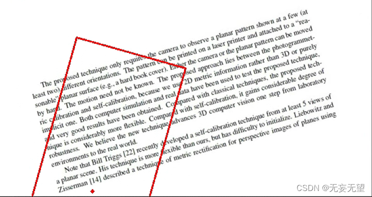
angle_p =cv.minAreaRect(coords)
box_points = cv.boxPoints(angle_p)
box_points = np.int0(box_points)
cv.circle(src, [146,284], 1, (0, 0, 255), 4)
srca = cv.drawContours(src, [box_points], -1, (0, 0, 255), 2)
》》》15.60267448425293
可以看到画出的外接矩形不能将文字全部包裹住,其角度为15.6,同样是以y轴正半轴为0°,顺时针为度数。
4.4 中心,角度,矩阵
cv.getRotationMatrix2D(center, angle, scale) → M
| 参数 | 说明 |
|---|---|
| center | 表示旋转中心坐标,二元元组 (x0, y0)。 |
| angle | 表示旋转角度,单位为角度,逆时针为正数,顺时针为负数。 |
| scale | 表示缩放因子。 |
4.5 仿射变换
需要说明的是,不管是霍夫线变换还是最小外接矩形,都是为了获取图像的一个倾斜角度。按上面画出的外接矩形来进行仿射变换来本不能完成校正,但是因为文字与x轴正半轴夹角为15.5,然后最小外接矩形的角度刚好是15.6,经过angle=-angle变换后,输入到旋转矩阵的角度就为-15.5,然后仿射变换的旋转就是,正数就是逆时针旋转,负数就是顺时针旋转,所以将原图顺时针旋转后,就刚好校正了。
参考: