🔎【博主简介】🔎
🏅CSDN博客专家
🏅2021年博客之星物联网与嵌入式开发TOP5
🏅2022年博客之星物联网与嵌入式开发TOP4
🏅2021年2022年C站百大博主
🏅华为云开发者社区专家博主
🏅阿里云开发者社区专家博主
🏅掘金INFOQ腾讯云优秀博主📝《个人主页》謓泽-CSDN博客
🥰《个人社区》QRS社区-CSDN社区云
👀《系列专栏》STM32-单片机
📣 点赞👍+ 收藏⭐️+ 留言💬⒈按键控制LED灯
概述⇢在五一单片机当中博主也有写过一篇关于轻触按键控制的文章,对轻触按键不了解的话可以看看🔗【51单片机】独立按键控制LED灯(四种形式)
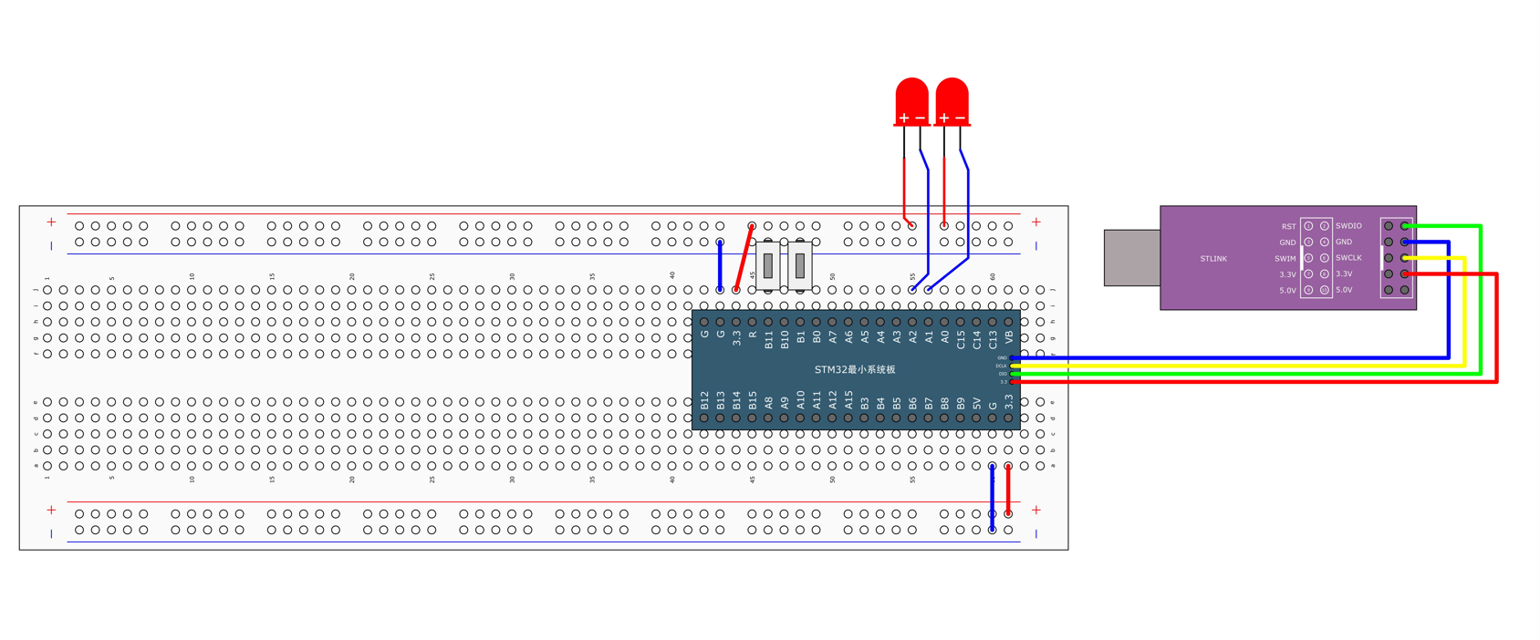
说明⇢在下述图当中是两个按键控制两个LED灯的面包板接线图。
说明⇢博主并非使用面包板接线图的,而是自己使用了洞洞板来焊接一个个模块,最终合成一个开发板的。就像和普中51的A2开发板一样。
示例要求如下👇
- 按下B1按键第一个LED点亮,再按一下B1按键LED灯熄灭。依次...
- 按下B11按键第二个LED点亮,再按一下B11按键LED灯熄灭。依次...
🎓拓展知识点如下⇣
- 快捷键CTRL+ALT+空格可以弹出代码提示框。
- 当我们把GPIO初始化配置好了之后单片机默认是低电平,所以我们需要再初始化完成之后再设置成高电平。
- 按键当中的初始化使用的Mode模式是上拉模式的。注:当然你也可以自己在外部电路上接一个上拉电阻,这样模式的选择也可以不用是上拉模式。
注意⇢按键会产生抖动,一般有两种方法可以解决按键产生抖动的问题。
⒈软件消抖、定时器扫描或延时函数。
⒉硬件消抖、小电容103并联接地。
第一个程序代码
示例代码如下◊
main.c
cpp#include "stm32f10x.h" // Device header #include "Delay.h" #include "LED.h" #include "Key.h" #include "stdint.h" uint8_t Ret; int main(void) { LED_Init(); Key_Init(); while (1) { Ret=KeyNum(); if(Ret==1) { LED1_Ture(); } else if(Ret==2) { LED2_Ture(); } else { LED3_Ture(); } } }LED.c
cpp#include "stm32f10x.h" // Device header /* 概述:LED的初始化函数。 ㈠使用RCC开启GPIO的时钟 [RCC-即复位与时钟控制,主要是通过寄存器配置时钟源] ㈡使用GPIO_Init函数初始化GPIO口。 ㈢使用输出或者输入函数控制GPIO口。 说明:快捷键[CTRL+ALT+空格]可以弹出代码提示框。 */ void LED_Init() { RCC_APB2PeriphClockCmd(RCC_APB2Periph_GPIOA|RCC_APB2Periph_GPIOC, ENABLE); GPIO_InitTypeDef GPIO_InitStructure; GPIO_InitStructure.GPIO_Mode = GPIO_Mode_Out_PP; GPIO_InitStructure.GPIO_Pin = GPIO_Pin_0 | GPIO_Pin_15 | GPIO_Pin_14; GPIO_InitStructure.GPIO_Speed = GPIO_Speed_50MHz; GPIO_Init(GPIOA, &GPIO_InitStructure); GPIO_Init(GPIOC, &GPIO_InitStructure); GPIO_SetBits(GPIOA, GPIO_Pin_0);//GPIO_Pin_x为高电平 GPIO_SetBits(GPIOC, GPIO_Pin_15 | GPIO_Pin_14); //GPIO_Pin_x为高电平 } //ON:打开 OFF:关闭 void LED1_ON() { GPIO_SetBits(GPIOA,GPIO_Pin_1); } void LED1_OFF() { GPIO_ResetBits(GPIOA,GPIO_Pin_1); } void LED2_ON() { GPIO_SetBits(GPIOC,GPIO_Pin_15); } void LED2_OFF() { GPIO_ResetBits(GPIOC,GPIO_Pin_15); } //IO电平翻转 void LED1_Ture() { if(GPIO_ReadOutputDataBit(GPIOA, GPIO_Pin_0) == 0) { //如果PA0的输出寄存器=0 GPIO_SetBits(GPIOA, GPIO_Pin_0);//PA1=1 } else//如果PA0的输出寄存器=1 { GPIO_ResetBits(GPIOA,GPIO_Pin_0);//PA1=0 } } void LED2_Ture() { if(GPIO_ReadOutputDataBit(GPIOC, GPIO_Pin_15) == 0) { GPIO_SetBits(GPIOC, GPIO_Pin_15); } else { GPIO_ResetBits(GPIOC,GPIO_Pin_15); } } void LED3_Ture() { if(GPIO_ReadOutputDataBit(GPIOC, GPIO_Pin_14) == 0) { GPIO_SetBits(GPIOC, GPIO_Pin_14); } else { GPIO_ResetBits(GPIOC,GPIO_Pin_14); } }LED.h
cpp#ifndef __LED_H #define __LED_H extern void LED_Init(void); extern void LED1_ON(void); extern void LED1_OFF(void); extern void LED2_ON(void); extern void LED2_OFF(void); extern void LED1_Ture(void); extern void LED2_Ture(void); extern void LED3_Ture(void); #endifKey.c
cpp#include "stm32f10x.h" // Device header #include "Delay.h" void Key_Init(void) { RCC_APB2PeriphClockCmd(RCC_APB2Periph_GPIOB, ENABLE); GPIO_InitTypeDef GPIO_InitStructure; GPIO_InitStructure.GPIO_Mode = GPIO_Mode_IPU; GPIO_InitStructure.GPIO_Pin = GPIO_Pin_1 | GPIO_Pin_11; GPIO_InitStructure.GPIO_Speed = GPIO_Speed_50MHz; GPIO_Init(GPIOB, &GPIO_InitStructure); } uint8_t Key_GetNum(void) { uint8_t KeyNum = 0; if (GPIO_ReadInputDataBit(GPIOB, GPIO_Pin_1) == 0) { Delay_ms(20); while (GPIO_ReadInputDataBit(GPIOB, GPIO_Pin_1) == 0); Delay_ms(20); KeyNum = 1; } if (GPIO_ReadInputDataBit(GPIOB, GPIO_Pin_11) == 0) { Delay_ms(20); while (GPIO_ReadInputDataBit(GPIOB, GPIO_Pin_11) == 0); Delay_ms(20); KeyNum = 2; } return KeyNum; }Key.h
cpp#ifndef __Key_H #define __Key_H extern void Key_Init(void); extern unsigned char KeyNum(void); #endif说明⇢以上便是独立按键控制LED的全部代码。
注意⇢在这里对应的按键是可以控制对应LED灯的以及翻转状态,当按键按下的时候对应的LED灯点亮、当按键松手的时候对应的LED灯熄灭。
cpp//大多数运用场景在IO口电平翻转 GPIO_ReadOutputDataBit(GPIOA, GPIO_Pin_0)⒉光敏传感器控制蜂鸣器
概述⇢第二个示例讲的是用光敏电阻传感器控制蜂鸣器。如果你对蜂鸣器不是很理解的话,推荐看看博主写的这篇文章。🔗
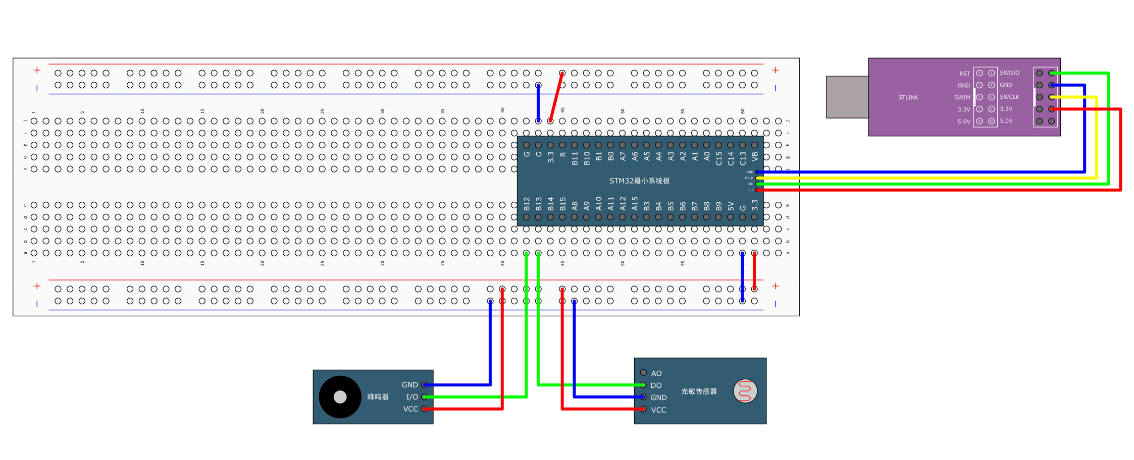
说明⇢在下述图当中是两个按键控制两个LED灯的面包板接线图。
重要知识点⇢在这里还是主要介绍下光敏传感器到底是啥玩意。
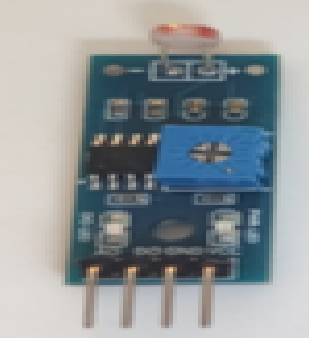
说明⇢在上述主要是由光敏电阻、电位器、电阻、LED灯、LM393组合而成的光敏传感器的模块,其主要功能是⇢光线越强,光敏电阻的阻值就会越小,信号输出低电平(灯亮),当遮挡光敏电阻的时候,信号输出为高电平(灯灭)
引脚⇢分别有四个引脚,1.Vcc、2.Gnd、3.AO、4.DO
注意⇢AO是ADC模数转换的引脚。
检测距离调节:顺时针调节电位器,检测距离增加;逆时针调节电位器,检测距离减少。
第二个程序代码
示例代码如下◊
main.h
cpp#include "stm32f10x.h" // Device header #include "Delay.h" #include "Buzzer.h" #include "LightSensor.h" int main(void) { Buzzer_Init(); LightSensor_Init(); while (1) { if (LightSensor_Get() == 1) { Buzzer_ON(); } else { Buzzer_OFF(); } } }Key.c
cpp#include "stm32f10x.h" // Device header #include "Delay.h" void Key_Init(void) { RCC_APB2PeriphClockCmd(RCC_APB2Periph_GPIOB, ENABLE); GPIO_InitTypeDef GPIO_InitStructure; GPIO_InitStructure.GPIO_Mode = GPIO_Mode_IPU; GPIO_InitStructure.GPIO_Pin = GPIO_Pin_1 | GPIO_Pin_11; GPIO_InitStructure.GPIO_Speed = GPIO_Speed_50MHz; GPIO_Init(GPIOB, &GPIO_InitStructure); } uint8_t Key_GetNum(void) { uint8_t KeyNum = 0; if (GPIO_ReadInputDataBit(GPIOB, GPIO_Pin_1) == 0) { Delay_ms(20); while (GPIO_ReadInputDataBit(GPIOB, GPIO_Pin_1) == 0); Delay_ms(20); KeyNum = 1; } if (GPIO_ReadInputDataBit(GPIOB, GPIO_Pin_11) == 0) { Delay_ms(20); while (GPIO_ReadInputDataBit(GPIOB, GPIO_Pin_11) == 0); Delay_ms(20); KeyNum = 2; } return KeyNum; }Key.h
cpp#ifndef __KEY_H #define __KEY_H void Key_Init(void); uint8_t Key_GetNum(void); #endifBuzzer.c
cpp#include "stm32f10x.h" // Device header void Buzzer_Init(void) { RCC_APB2PeriphClockCmd(RCC_APB2Periph_GPIOB, ENABLE); GPIO_InitTypeDef GPIO_InitStructure; GPIO_InitStructure.GPIO_Mode = GPIO_Mode_Out_PP; GPIO_InitStructure.GPIO_Pin = GPIO_Pin_12; GPIO_InitStructure.GPIO_Speed = GPIO_Speed_50MHz; GPIO_Init(GPIOB, &GPIO_InitStructure); GPIO_SetBits(GPIOB, GPIO_Pin_12); } void Buzzer_ON(void) { GPIO_ResetBits(GPIOB, GPIO_Pin_12); } void Buzzer_OFF(void) { GPIO_SetBits(GPIOB, GPIO_Pin_12); } void Buzzer_Turn(void) { if (GPIO_ReadOutputDataBit(GPIOB, GPIO_Pin_12) == 0) { GPIO_SetBits(GPIOB, GPIO_Pin_12); } else { GPIO_ResetBits(GPIOB, GPIO_Pin_12); } }Buzzer.h
cpp#ifndef __BUZZER_H #define __BUZZER_H void Buzzer_Init(void); void Buzzer_ON(void); void Buzzer_OFF(void); void Buzzer_Turn(void); #endifLightSensor.c
cpp#include "stm32f10x.h" // Device header void LightSensor_Init(void) { RCC_APB2PeriphClockCmd(RCC_APB2Periph_GPIOB, ENABLE); GPIO_InitTypeDef GPIO_InitStructure; GPIO_InitStructure.GPIO_Mode = GPIO_Mode_IPU; GPIO_InitStructure.GPIO_Pin = GPIO_Pin_13; GPIO_InitStructure.GPIO_Speed = GPIO_Speed_50MHz; GPIO_Init(GPIOB, &GPIO_InitStructure); } uint8_t LightSensor_Get(void) { return GPIO_ReadInputDataBit(GPIOB, GPIO_Pin_13); }LightSensor.h
cpp#ifndef __LIGHT_SENSOR_H #define __LIGHT_SENSOR_H void LightSensor_Init(void); uint8_t LightSensor_Get(void); #endif说明⇢以上便是第二个示例代码的全部程序内容。
【STM32】按键控制LED & 光敏传感器控制蜂鸣器
謓泽2025-05-29 16:53

相关推荐
GeekArch20 分钟前
第24讲:Vibe模式代码风格控制——适配Keil/STM32工程规范Freedom_my1 小时前
STM32项目3国科安芯2 小时前
星间光链路:AS32S601型抗辐射MCU在空间激光通信终端控制中的技术实现小李不困还能学4 小时前
基于 51 单片机的8 路抢答器设计教程萌动的小火苗4 小时前
嵌入式开发中的栈与队列:任务调度为什么依赖数据结构振浩微433射频芯片5 小时前
工业遥控器总在关键时刻“掉链子”?——433MHz芯片方案如何破局blevoice5 小时前
抖抖燃脂机单 AC6966B 主控调试踩坑:Type-C 整机供电喇叭无声排障三易串口屏6 小时前
三易串口屏开发教程:如何使用键盘控件输入参数并发送给单片机十月的皮皮7 小时前
STM32从零到量产开发:四路继电器工业控制模块开发实战笔记(小白视角)2CM_Embed7 小时前
F28379D 下载后 VOFA+ 无数据、Reset 后恢复:一次 TZ 中断误触发排查记录