什么是 ADC(模数转换器)
ADC(Analog to Digital Converter)是将 模拟信号(电压)转换成数字信号(数值) 的器件。
在 STM32 中,ADC 通常具有以下特性:
| 特性 | 描述 |
|---|---|
| 分辨率 | 12 位(即 0 ~ 4095) |
| 输入电压范围 | 0 ~ 3.3V(取决于 VREF+) |
| 转换方式 | 单次转换、连续转换、扫描模式 |
| 支持触发方式 | 软件触发 / 硬件定时器 / 外部中断 |
| 支持 DMA | 可配合 DMA 进行高效数据采集 |
STM32 + HAL 库 + 光敏传感器 + ADC 采集的实现
这里我们的示例是通过 STM32 的 ADC 采集光敏传感器的模拟电压值,并通过串口将 ADC 数值发送到上位机显示。
ADC 硬件配置(STM32CubeMX)
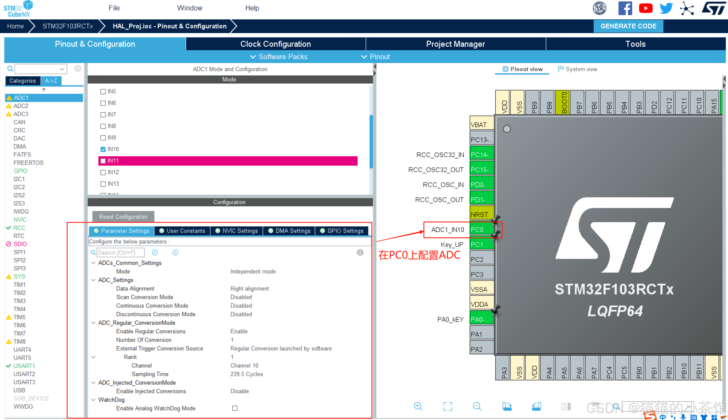
此处的 ADC 配置:
项目							配置内容
ADC 通道						ADC1_IN10(对应 PC0)
模式							Independent mode
数据对齐						Right alignment(右对齐)
Regular Conversion Mode		Enabled
Conversion Trigger			Software trigger(软件触发)
Sampling Time				239.5 cycles(采样时间越长越稳定)

PC0 接入光敏传感器的模拟输出
CubeMX 配置步骤:
1. 选择 ADC 模拟通道
	比如:选择 ADC1_IN10(对应 PC0 引脚)
2. 配置 ADC 模式
	Mode:Independent Mode
	Scan Conversion Mode:Disabled(若单通道)
	Continuous Conversion:Disabled(手动触发)
	Sampling Time:推荐设置较长,如 239.5 cycles(提升稳定性)
3. 开启 ADC
	勾选"Enable Regular Conversion"
	设置触发方式为:Software Trigger(软件控制启动)
HAL 库中常用 ADC 函数
| 函数 | 作用 |
|---|---|
HAL_ADC_Start() |
启动 ADC 转换 |
HAL_ADC_PollForConversion() |
等待转换完成(阻塞) |
HAL_ADC_GetValue() |
获取转换值(0 ~ 4095) |
HAL_ADC_Stop() |
停止转换 |
HAL_ADC_Start_DMA() |
启动 DMA 模式采集 |
HAL_ADCEx_Calibration_Start() |
启动校准(部分芯片支持) |
HAL 库 API 调用(main.c)
📄 main.c
c
/* USER CODE BEGIN Header */
/**
  ******************************************************************************
  * @file           : main.c
  * @brief          : Main program body
  ******************************************************************************
  * @attention
  *
  * Copyright (c) 2025 STMicroelectronics.
  * All rights reserved.
  *
  * This software is licensed under terms that can be found in the LICENSE file
  * in the root directory of this software component.
  * If no LICENSE file comes with this software, it is provided AS-IS.
  *
  ******************************************************************************
  */
/* USER CODE END Header */
/* Includes ------------------------------------------------------------------*/
#include "main.h"
#include "adc.h"
#include "usart.h"
#include "gpio.h"

/* Private includes ----------------------------------------------------------*/
/* USER CODE BEGIN Includes */
#include "string.h"
/* USER CODE END Includes */

/* Private typedef -----------------------------------------------------------*/
/* USER CODE BEGIN PTD */

/* USER CODE END PTD */

/* Private define ------------------------------------------------------------*/
/* USER CODE BEGIN PD */
/* USER CODE END PD */

/* Private macro -------------------------------------------------------------*/
/* USER CODE BEGIN PM */

/* USER CODE END PM */

/* Private variables ---------------------------------------------------------*/

/* USER CODE BEGIN PV */

/* USER CODE END PV */

/* Private function prototypes -----------------------------------------------*/
void SystemClock_Config(void);
/* USER CODE BEGIN PFP */

/* USER CODE END PFP */

/* Private user code ---------------------------------------------------------*/
/* USER CODE BEGIN 0 */
uint16_t ADC_Value = 0;
/* USER CODE END 0 */

/**
  * @brief  The application entry point.
  * @retval int
  */
int main(void)
{
  /* USER CODE BEGIN 1 */
  /* USER CODE END 1 */

  /* MCU Configuration--------------------------------------------------------*/

  /* Reset of all peripherals, Initializes the Flash interface and the Systick. */
  HAL_Init();

  /* USER CODE BEGIN Init */

  /* USER CODE END Init */

  /* Configure the system clock */
  SystemClock_Config();

  /* USER CODE BEGIN SysInit */

  /* USER CODE END SysInit */

  /* Initialize all configured peripherals */
  MX_GPIO_Init();
  MX_USART1_UART_Init();
  MX_ADC1_Init();
  /* USER CODE BEGIN 2 */
	HAL_UARTEx_ReceiveToIdle_IT(  &huart1 , U1RxData, U1RxDataSize);

	HAL_ADCEx_Calibration_Start( &hadc1 );  //开启校准

  /* USER CODE END 2 */

  /* Infinite loop */
  /* USER CODE BEGIN WHILE */

  while (1)
  {
		HAL_ADC_Start( &hadc1 );  //开启ADC转换
		HAL_ADC_PollForConversion( &hadc1, 50); //等待转换完成

		if(HAL_IS_BIT_SET( HAL_ADC_GetState( &hadc1 ), HAL_ADC_STATE_REG_EOC) ) //判断是否转换完成
		{
			ADC_Value = HAL_ADC_GetValue(&hadc1);

			printf(" ADC_Value = %d \r\n",ADC_Value);
		}

		HAL_Delay(1000);

    /* USER CODE END WHILE */

    /* USER CODE BEGIN 3 */
  }
  /* USER CODE END 3 */
}

/**
  * @brief System Clock Configuration
  * @retval None
  */
void SystemClock_Config(void)
{
  RCC_OscInitTypeDef RCC_OscInitStruct = {0};
  RCC_ClkInitTypeDef RCC_ClkInitStruct = {0};
  RCC_PeriphCLKInitTypeDef PeriphClkInit = {0};

  /** Initializes the RCC Oscillators according to the specified parameters
  * in the RCC_OscInitTypeDef structure.
  */
  RCC_OscInitStruct.OscillatorType = RCC_OSCILLATORTYPE_HSE;
  RCC_OscInitStruct.HSEState = RCC_HSE_ON;
  RCC_OscInitStruct.HSEPredivValue = RCC_HSE_PREDIV_DIV1;
  RCC_OscInitStruct.HSIState = RCC_HSI_ON;
  RCC_OscInitStruct.PLL.PLLState = RCC_PLL_ON;
  RCC_OscInitStruct.PLL.PLLSource = RCC_PLLSOURCE_HSE;
  RCC_OscInitStruct.PLL.PLLMUL = RCC_PLL_MUL9;
  if (HAL_RCC_OscConfig(&RCC_OscInitStruct) != HAL_OK)
  {
    Error_Handler();
  }

  /** Initializes the CPU, AHB and APB buses clocks
  */
  RCC_ClkInitStruct.ClockType = RCC_CLOCKTYPE_HCLK|RCC_CLOCKTYPE_SYSCLK
                              |RCC_CLOCKTYPE_PCLK1|RCC_CLOCKTYPE_PCLK2;
  RCC_ClkInitStruct.SYSCLKSource = RCC_SYSCLKSOURCE_PLLCLK;
  RCC_ClkInitStruct.AHBCLKDivider = RCC_SYSCLK_DIV1;
  RCC_ClkInitStruct.APB1CLKDivider = RCC_HCLK_DIV2;
  RCC_ClkInitStruct.APB2CLKDivider = RCC_HCLK_DIV1;

  if (HAL_RCC_ClockConfig(&RCC_ClkInitStruct, FLASH_LATENCY_2) != HAL_OK)
  {
    Error_Handler();
  }
  PeriphClkInit.PeriphClockSelection = RCC_PERIPHCLK_ADC;
  PeriphClkInit.AdcClockSelection = RCC_ADCPCLK2_DIV6;
  if (HAL_RCCEx_PeriphCLKConfig(&PeriphClkInit) != HAL_OK)
  {
    Error_Handler();
  }
}

/* USER CODE BEGIN 4 */

/* USER CODE END 4 */

/**
  * @brief  This function is executed in case of error occurrence.
  * @retval None
  */
void Error_Handler(void)
{
  /* USER CODE BEGIN Error_Handler_Debug */
  /* User can add his own implementation to report the HAL error return state */
  __disable_irq();
  while (1)
  {
  }
  /* USER CODE END Error_Handler_Debug */
}

#ifdef  USE_FULL_ASSERT
/**
  * @brief  Reports the name of the source file and the source line number
  *         where the assert_param error has occurred.
  * @param  file: pointer to the source file name
  * @param  line: assert_param error line source number
  * @retval None
  */
void assert_failed(uint8_t *file, uint32_t line)
{
  /* USER CODE BEGIN 6 */
  /* User can add his own implementation to report the file name and line number,
     ex: printf("Wrong parameters value: file %s on line %d\r\n", file, line) */
  /* USER CODE END 6 */
}
#endif /* USE_FULL_ASSERT */
ADC代码逻辑:
c
HAL_ADC_Start(&hadc1); // 启动ADC
HAL_ADC_PollForConversion(&hadc1, 50); // 等待转换完成(阻塞,最多50ms)
if(HAL_IS_BIT_SET(HAL_ADC_GetState(&hadc1), HAL_ADC_STATE_REG_EOC))
{
ADC_Value = HAL_ADC_GetValue(&hadc1); // 获取ADC值(0~4095)
printf("ADC_Value = %d\r\n", ADC_Value); // 通过串口发送
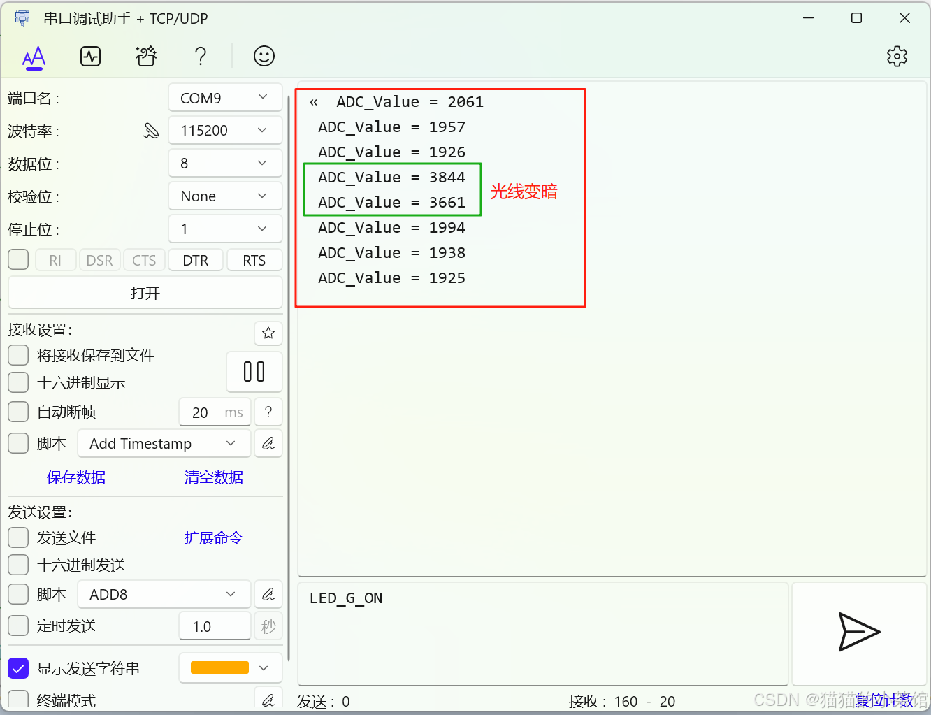
}✅ ADC 数据类型说明:
ADC 是 12 位精度,HAL_ADC_GetValue() 返回值范围为:
c
0 ~ 4095(对应 0V ~ 3.3V)

例如:
ADC_Value = 1926 → 电压约为 1926 / 4095 * 3.3 ≈ 1.55V
ADC_Value = 3844 → 电压约为 3.1V(光线强)
串口调试助手实时查看采样数据
光照强度变化的验证(ADC 值高低变化)
ADC 原始值与电压换算
STM32 的 ADC 通常是 12 位,最大值为 4095,换算公式如下:
c
电压值(V) = adc_value / 4095.0 * 参考电压(通常是 3.3V)比如:
adc_value = 2048→ 电压约为1.65V*adc_value = 4095→ 电压约为3.3V
这里拿光敏传感器作为ADC的例子介绍,但ADC的应用场景还有很多:① 光敏传感器,根据光照强度输出电压,ADC 采集判断亮度;② 热敏电阻,电压随温度变化,用 ADC 采样计算温度;③ 电池电压检测,ADC 采集电池端电压,判断电量;④ 模拟摇杆,采集 X/Y 两轴的电压值进行控制;⑤ 电位器调节,采集旋转角度电压,作为输入参数。
此外,ADC还存在一些进阶用法,感兴趣的小伙伴可自行深入:
多通道采集	开启 Scan Mode,配置多个通道
连续采样		Continuous Mode = Enabled
DMA 模式		使用 HAL_ADC_Start_DMA() 实现高效采集
外部触发		使用定时器 / 外部中断触发 ADC
滤波处理		多次采集后取平均值 / 中值滤波提高准确性
以上。 这便是 STM32 + HAL 库 + 光敏传感器 + ADC 采集 的实现。
以上,欢迎有从事同行业的电子信息工程、互联网通信、嵌入式开发的朋友共同探讨与提问,我可以提供实战演示或模板库。希望内容能够对你产生帮助!