Xilinx FIFO的两种读模式
目标
本文主要是对 Xilinx FIFO中的两种读模式:Standard 与 FWFT 模式进行简单的分析。弄清楚在设置不同的读写长度下,两种模式内部信号是如何变化的,有什么差异。便于后续使用这个IP
FWFT模式相比Strandard模式的特点
在First-Word-Fall-Through(FWFT)读模式下,用户可以预先的查看FIFO中下一个数据内容。读潜伏期为0
而在Standard模式下,用户在发起读使能后,经过1个或者2个读潜伏期后,才能读取数据。读潜伏期>1
实验配置
实验环境在Vivado 2021. 1 下进行,使用modelsim 作为仿真工具
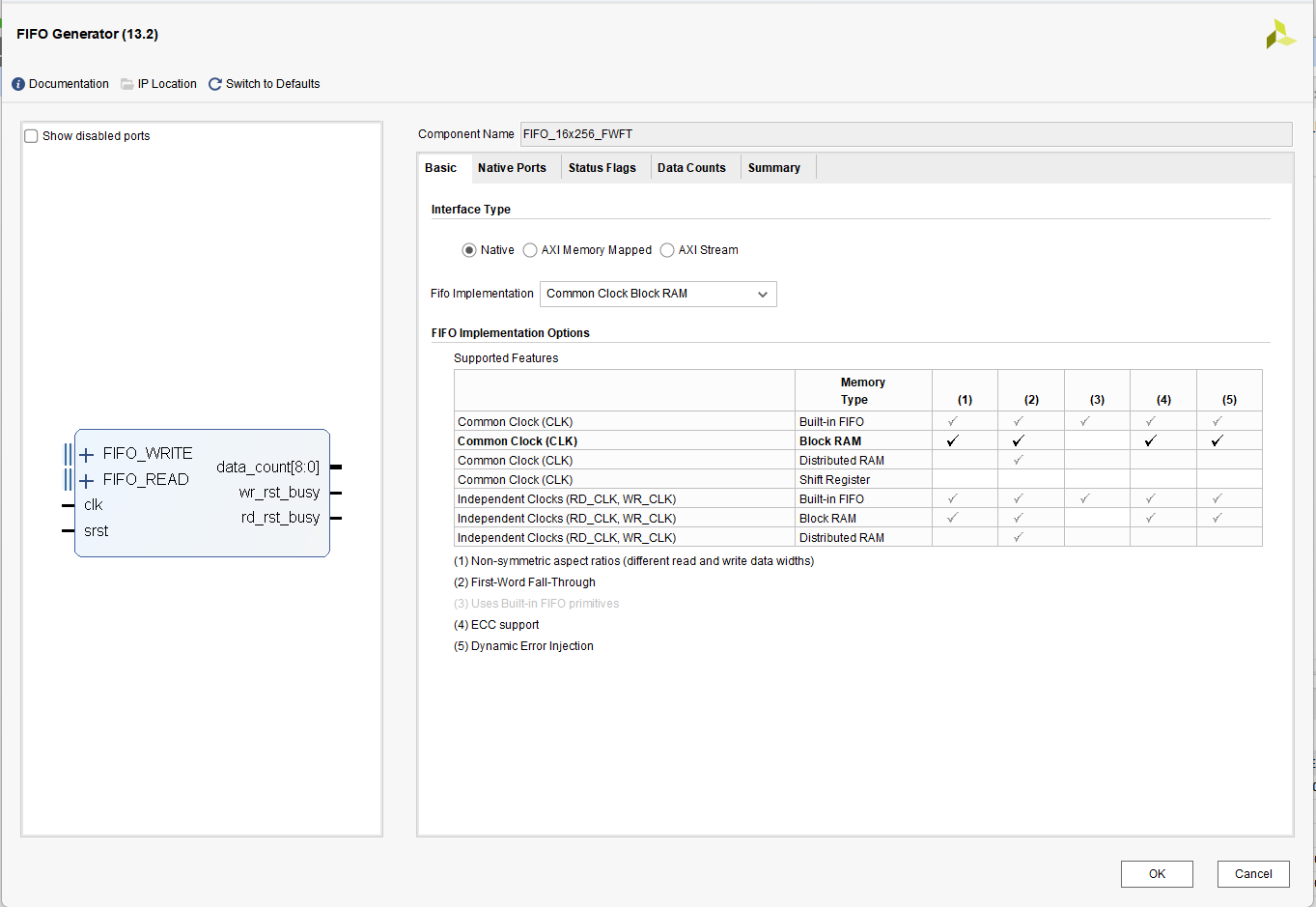
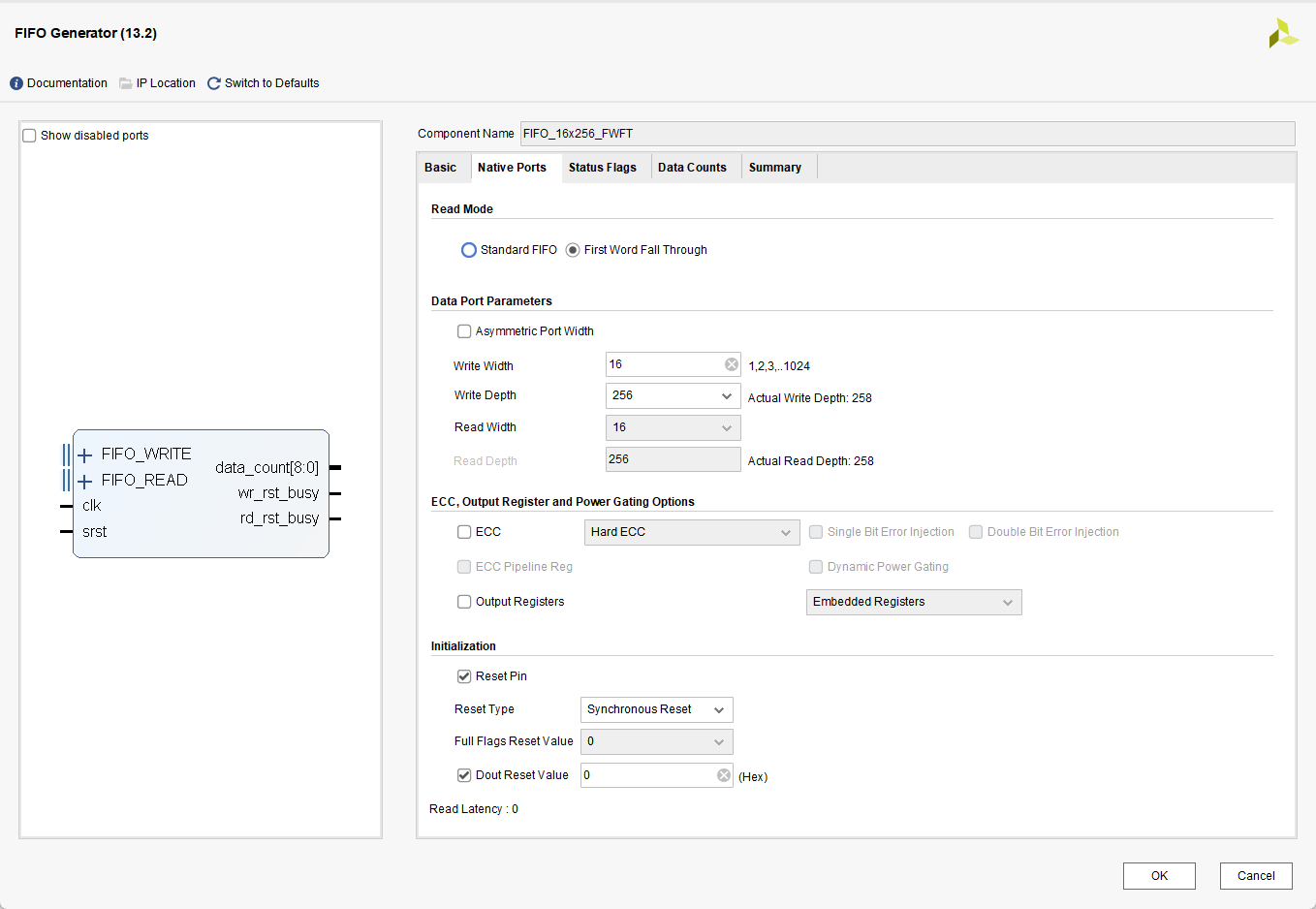
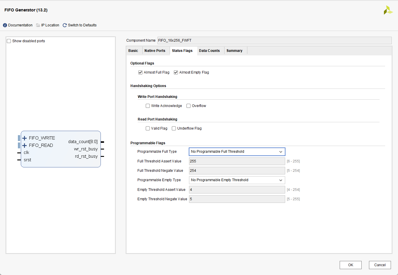
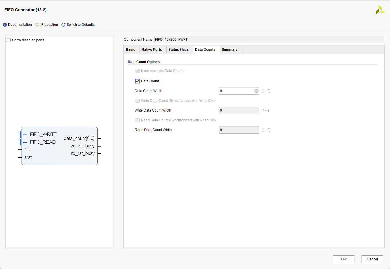
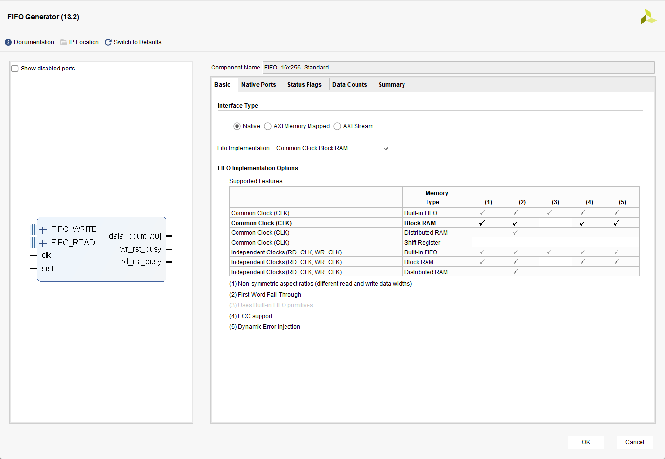
本文设置FIFO数据宽度为 16 位,数据深度为256 , 同时设置了一些常用的信号,具体配置如下:
对于 FWFT模式的实验配置如下
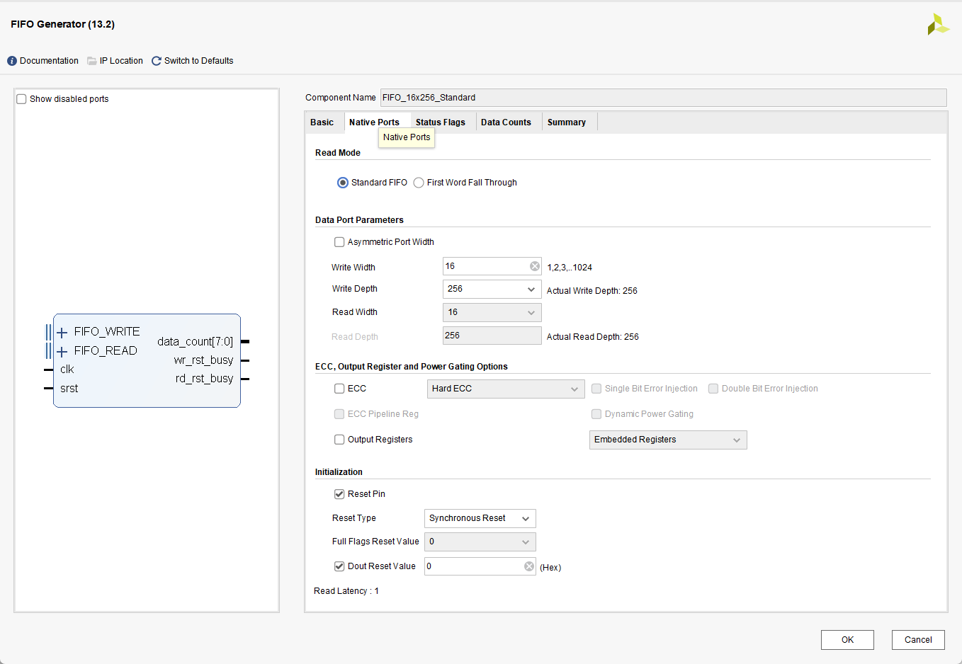
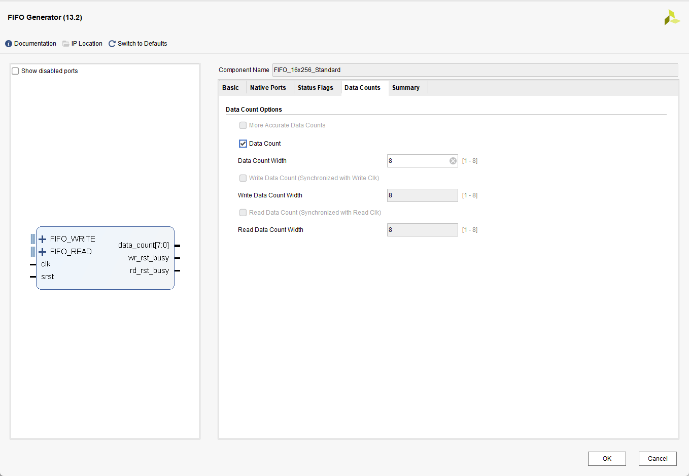
对于 Standard模式的实验配置如下
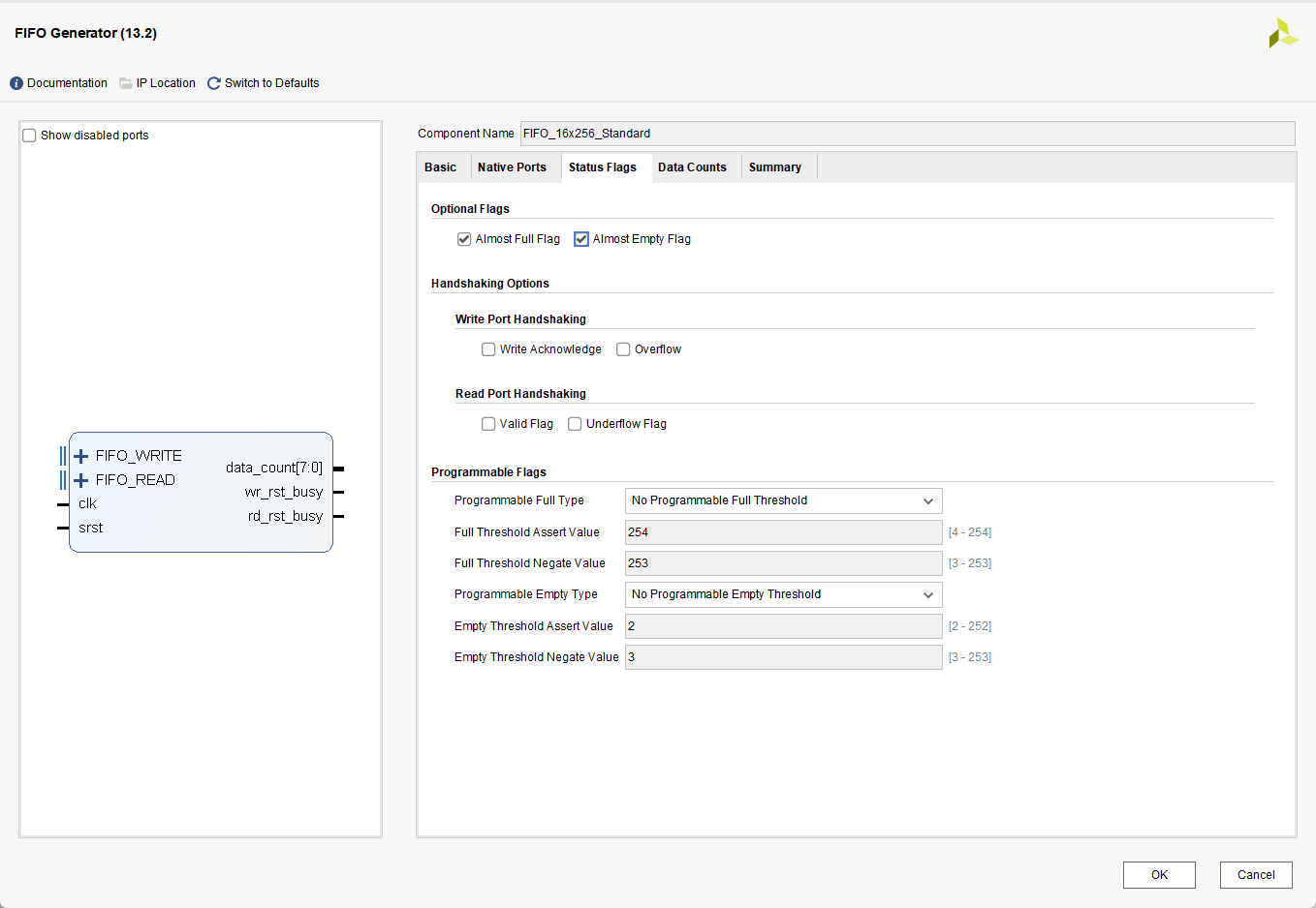
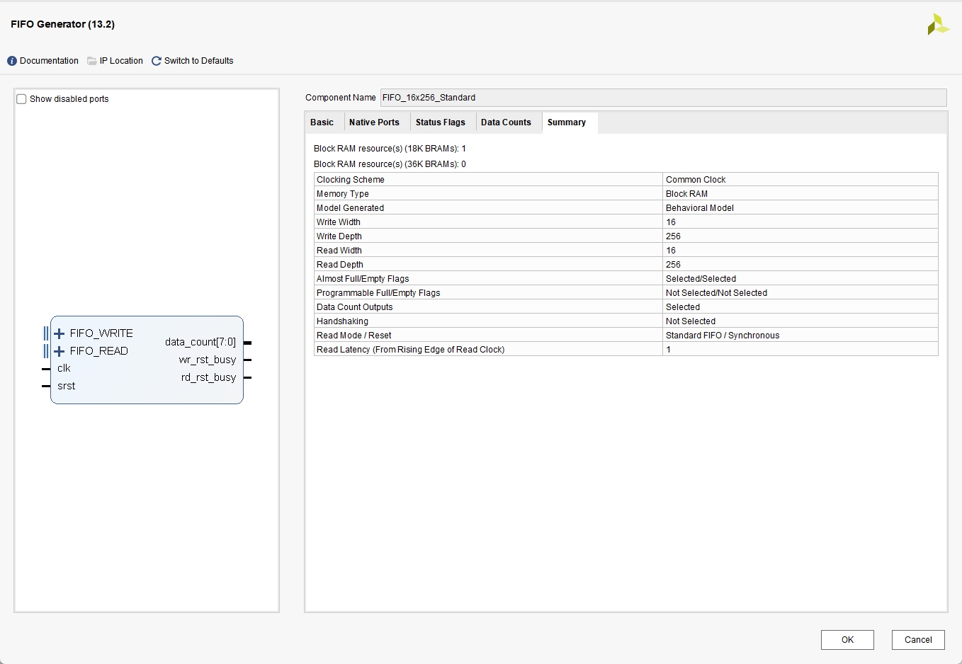
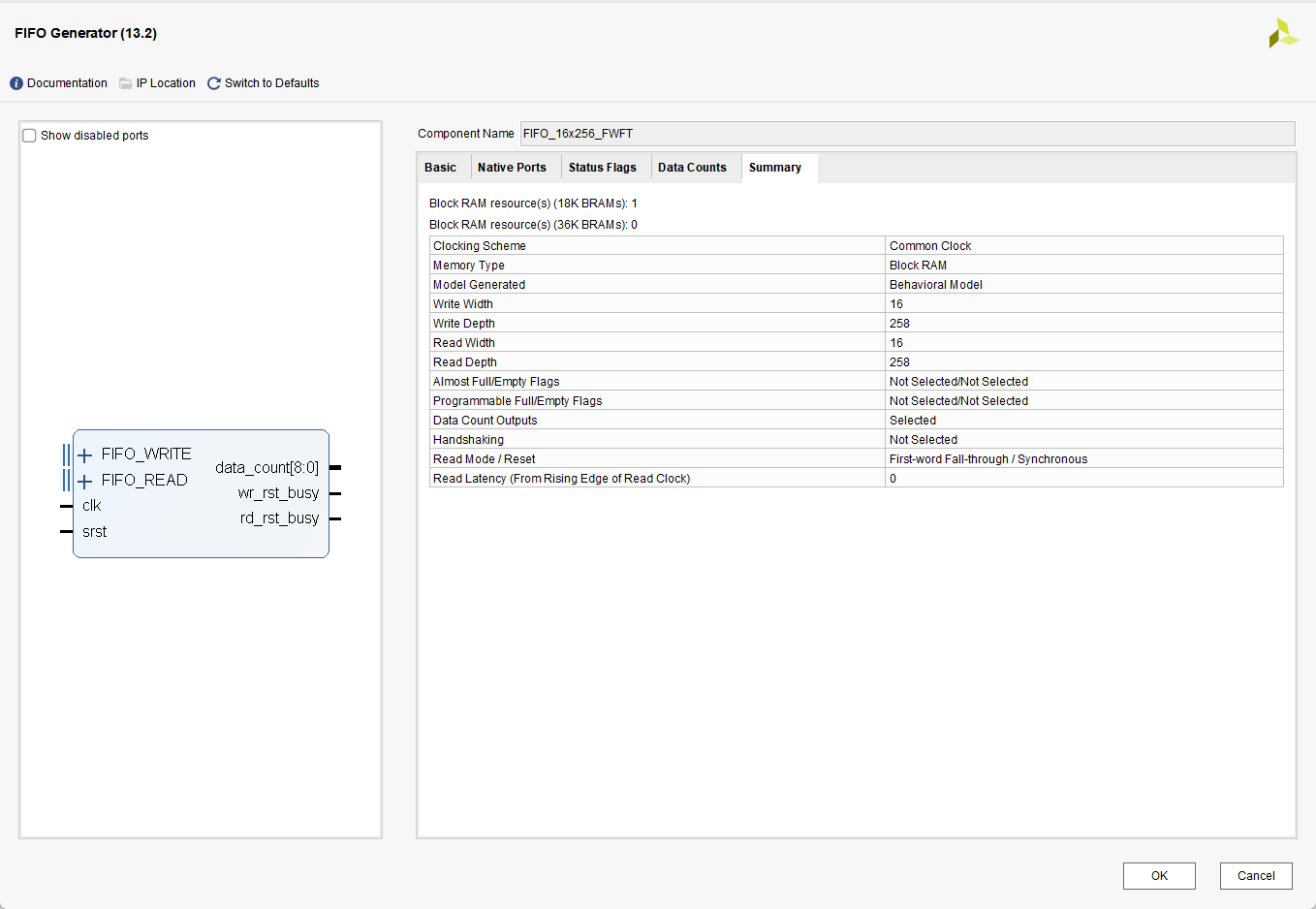
从两种模式配置的总结页面可以看到二者的有
1. 对于FWFT模式 读潜伏期为0 ,而Standard模式 读潜伏期为1
2. 对于FWFT模式,数据深度相比设置的256, 增加至了258。而Standard模式没有发生改变
实验代码
在代码中,对FIFO的一些临界情况,以及普通情况进行了测试,具体如下
C
`timescale 1ns/1ps
module tb_fifo();

reg      i_clk     ;
reg      i_rst     ;

initial begin
    i_clk = 0;
end

always #5 i_clk = ~i_clk;


reg   [15:0]        i_din       ;
reg                 i_din_valid ;
reg                 i_rd_en     ;

wire  [15:0]        w_fifo_fwft_dout   ;
wire                w_fifo_fwft_empty  ;
wire                w_fifo_fwft_full   ;
wire  [8:0]         w_fifo_fwft_count  ;
wire                w_fifo_fwft_wrbusy ;
wire                w_fifo_fwft_rdbusy ;
wire                w_fifo_fwft_almost_full ;
wire                w_fifo_fwft_almost_empty;

wire  [15:0]        w_fifo_standard_dout   ;
wire                w_fifo_standard_full   ;
wire                w_fifo_standard_empty  ;
wire  [7:0]         w_fifo_standard_count  ;
wire                w_fifo_standard_wrbusy ;
wire                w_fifo_standard_rdbusy ;
wire                w_fifo_standard_almost_full ;
wire                w_fifo_standard_almost_empty;

initial begin
    gen_rst(10);
end

initial begin
    i_din = 0;
    i_din_valid  = 0;
    i_rd_en = 0;
    wait(~i_rst);
    @(posedge i_clk);
    //读写一个数据
    gen_din(1);
    repeat(2) @(posedge i_clk);
    gen_rd_en(1);

    //读写两个数据
    repeat(5) @(posedge i_clk);
    gen_din(2);
    repeat(2) @(posedge i_clk);
    gen_rd_en(2);

    //读写255个数据
    repeat(5) @(posedge i_clk);
    gen_din(255);
    repeat(2) @(posedge i_clk);
    gen_rd_en(255);

    //读写256个数据
    repeat(5) @(posedge i_clk);
    gen_din(256);
    repeat(2) @(posedge i_clk);
    gen_rd_en(256);

    //读写257个数据
    repeat(5) @(posedge i_clk);
    gen_din(257);
    repeat(2) @(posedge i_clk);
    gen_rd_en(257);

    //读写258个数据
    repeat(5) @(posedge i_clk);
    gen_din(258);
    repeat(2) @(posedge i_clk);
    gen_rd_en(258);

    //读写259个数据
    repeat(5) @(posedge i_clk);
    gen_din(259);
    repeat(2) @(posedge i_clk);
    gen_rd_en(259);
end

task gen_rst(input [15:0] Tcnt);
begin
    i_rst = 1;
    repeat(Tcnt) @(posedge i_clk);
    i_rst = 0;
end
endtask

task gen_rd_en(input [15:0] Tcnt);
begin
    i_rd_en = 1  ;
    repeat(Tcnt) @(posedge i_clk);
    i_rd_en = 0  ;
end
endtask

task gen_din(input [15:0] data);
integer i;
begin
   for(i = 1 ; i <= data ; i = i + 1)
   begin
        i_din = i;
        i_din_valid = 1;
        @(posedge i_clk);
    end
   i_din = 0;
   i_din_valid = 0;
end
endtask


FIFO_16x256_FWFT FIFO_16x256_FWFT_U0 (
    .clk                               (i_clk                     ),// input wire clk
    .srst                              (i_rst                     ),// input wire srst
    .din                               (i_din                     ),// input wire [17 : 0] din
    .wr_en                             (i_din_valid               ),// input wire wr_en
    .rd_en                             (i_rd_en                   ),// input wire rd_en
    .dout                              (w_fifo_fwft_dout          ),// output wire [17 : 0] dout
    .full                              (w_fifo_fwft_full          ),// output wire full
    .almost_full                       (w_fifo_fwft_almost_full   ),// output wire almost_full
    .empty                             (w_fifo_fwft_empty         ),// output wire empty
    .almost_empty                      (w_fifo_fwft_almost_empty  ),// output wire almost_empty
    .data_count                        (w_fifo_fwft_count         ),// output wire [10 : 0] data_count
    .wr_rst_busy                       (w_fifo_fwft_wrbusy        ),// output wire wr_rst_busy
    .rd_rst_busy                       (w_fifo_fwft_rdbusy        ) // output wire rd_rst_busy
);


FIFO_16x256_Standard FIFO_16x256_Standard_U0 (
    .clk                               (i_clk                        ),// input wire clk
    .srst                              (i_rst                        ),// input wire srst
    .din                               (i_din                        ),// input wire [17 : 0] din
    .wr_en                             (i_din_valid                  ),// input wire wr_en
    .rd_en                             (i_rd_en                      ),// input wire rd_en
    .dout                              (w_fifo_standard_dout         ),// output wire [17 : 0] dout
    .full                              (w_fifo_standard_full         ),// output wire full
    .almost_full                       (w_fifo_standard_almost_full  ),// output wire almost_full
    .empty                             (w_fifo_standard_empty        ),// output wire empty
    .almost_empty                      (w_fifo_standard_almost_empty ),// output wire almost_empty
    .data_count                        (w_fifo_standard_count        ),// output wire [9 : 0] data_count
    .wr_rst_busy                       (w_fifo_standard_wrbusy       ),// output wire wr_rst_busy
    .rd_rst_busy                       (w_fifo_standard_rdbusy       ) // output wire rd_rst_busy
);

endmodule
实验分析
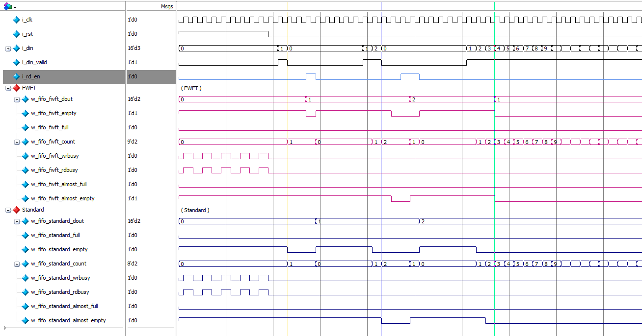
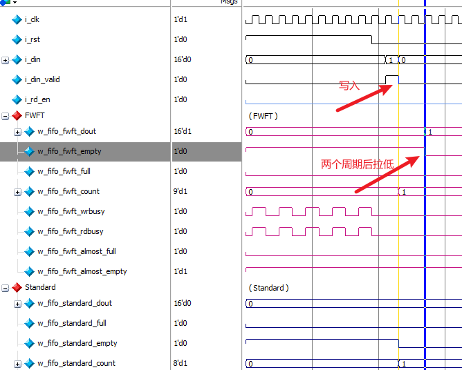
i_din_valid 作为两个FIFO的写入使能,可以观察到写入一个数据后,对于Standard模式 empty信号立即拉低,而对于FWFT模式empty信号并不会立即拉低。当写入三个数据后,FWFT模式下的empty信号才拉低,也可以理解为FWFT模式下,写入数据后延迟两个时钟周期empty才会拉低
将读写的周期加大后,可以看到确实如此。
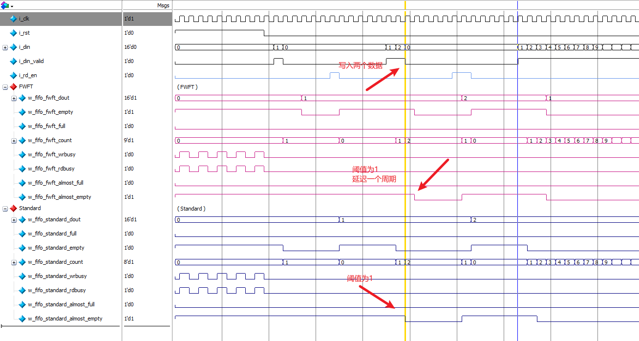
写入两个数据后,对于Standard模式,almost_empty 会拉低,说明几乎空信号 最低的阈值是1。对于FWFT模式,almost_empty 在延迟一个周期后才会拉低,说明几乎空信号 最低的阈值也是1,或者可以理解为在连续写入的过程中,FWFT模式下,几乎空信号 最低的阈值是2
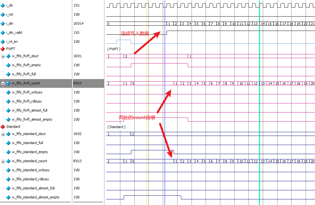
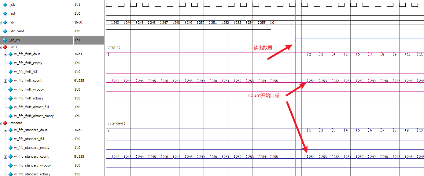
对于count信号 ,两种模式下写入时都会开始自增,读出数据时开始自减。
同时也可以看到在FWFT模式下,dout 输出与i_rd_en 读使能是同步的
而在Standard模式下,dout 输出与i_rd_en 读使能相差一个时钟周期。
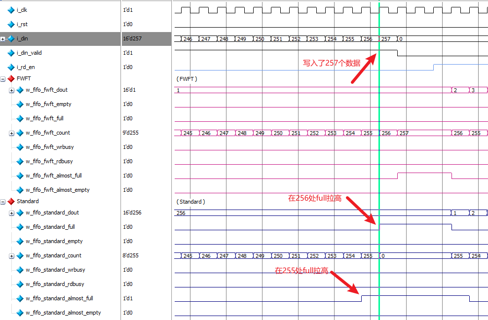
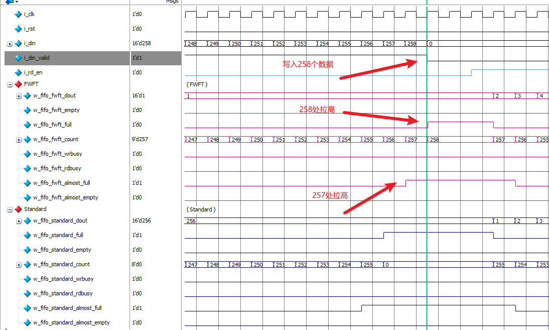
配置完成时,在IP的总结页面上可以看到Standard模式下最大的数据深度为256 ,在波形图中可以看到当写入257个数据时,full信号 在256处被拉高了,而almost_full信号 在255处被拉高。
在FWFT模式下最大的数据深度为258 ,在波形图中可以看到当写入258个数据时,full信号 在258处被拉高了,而almost_full信号 在257处被拉高。
两种模式下,full信号 都是在写入数据最大深度后立即拉低,almost_full信号阈值都是1
总结
| 信号 | FWFT模式 | Standard模式 | 备注 |
|---|---|---|---|
| 读潜伏期 | 0 | 1 | 一般详细的数值可以看配置界面的总结部分 |
| dout | 用户可以提前看到下一个数据的值,数据相较读使能没有延迟 | 需要等待读使能的触发,数据相较读使能延迟一个时钟周期 | 无 |
| full | 在写入数据最大深度后立即拉低 | 在写入数据最大深度后立即拉低 | 无 |
| empty | 写入数据后 ,延迟两个时钟周期拉低或写入三个数据后拉低 | 数据写入后,信号立即拉低 | 无 |
| almost_full | 阈值为1,写入最大数据深度-1时拉高 | 阈值为1,写入最大数据深度-1时拉高 | 无 |
| almost_empty | 阈值为1,写入两个数据后延迟一个周期后才会拉低或连续写入下,阈值为2 | 阈值为1,写入两个数据后信号拉低 | 无 |
| data_cout | 写时自增,读时自减 | 写时自增,读时自减 | 无 |