一、先写下解决方法,debug过程就当做乐子给大家看吧。
问题原因:
reset顺序颠倒。
解决方法:
static void fbtft_reset(struct fbtft_par *par)里,将
gpiod_set_value_cansleep(1)
gpiod_set_value_cansleep(0)
修改为
gpiod_set_value_cansleep(0)
gpiod_set_value_cansleep(1)
一些参考链接,但是不是我遇到的问题
全志v851s使用fbtft驱动0.96寸st7735屏分享 | 全志在线开发者论坛
求助荔枝派zero 驱动st7735 0.96寸spi屏幕 / 全志 SOC / WhyCan Forum(哇酷开发者社区)
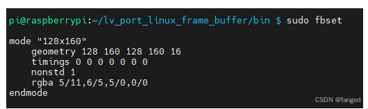
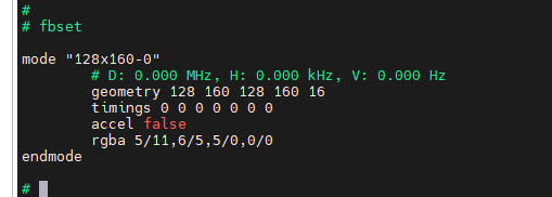
用户态fbset上看也没问题:
二、尝试从硬件/pull up上解决
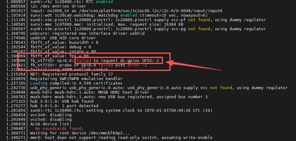
问题现入僵局,从软件上看一切正常,但是st7735是没有输出的,芯片也看不到是否运行正常。所以拿出示波器,看到reset脚一直是拉低的。
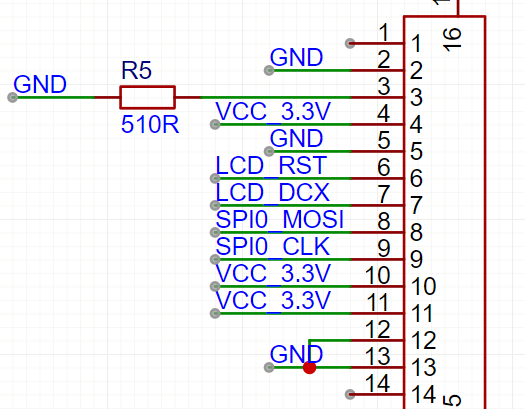
检查原理图:
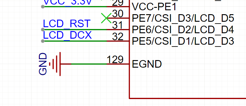
网上都在说reset,dc要加上拉之类的。我没有加,难道是因为没有配置成上拉模式吗?(其实这里被网络上带偏了,后来才发现)。那么是加上拉有两种方式:
1、通过硬件的方式,因为拉测试点时,已经将reset信号拉出,只需要接到按键的上拉电阻就完事。
2、通过软件配置PE6,也就是reset脚为上拉输出。(万一配置成了开漏,或都弱输出也是会影响信号的。那样再改回来就行)。
想着按方法一,但是最后还是要要改软件。而且方法一一定可行,不需要再试了。就打算用方法二,其实电烙铁已经准备好了,就是不想动手焊来回跑。
修改设备树sun8i-v3s.dtsi,在pio下添加:
cpp
tft_lcd_pins: tft-lcd-pins {
				pins = "PE5", "PE6";
				function = "gpio_out";
				bias-pull-up;
			};
修改设备树sun8i-v3s-licheepi-zero-with-st7735-lcd.dts:
cpp
pinctrl-names = "default";
		pinctrl-0 = <&tft_lcd_pins>;
		dc-gpios = <&pio 4 5 GPIO_ACTIVE_HIGH>; // PE5
		reset-gpios = <&pio 4 6 GPIO_ACTIVE_LOW>; // PE6
结果pinctrl-0 = <&tft_lcd_pins>;与
dc-gpios = <&pio 4 5 GPIO_ACTIVE_HIGH>; // PE5
reset-gpios = <&pio 4 6 GPIO_ACTIVE_LOW>; // PE6
冲突了,重复request 同一个gpio。
相关问题可以看我的另一篇文章:
3、于是换一种方法,手动设置pe6为上拉:
cpp
static int fbtft_request_gpios(struct fbtft_par *par)
{
	int i;
	int ret;
	int* temp;
	int* config;
	int* driver;
	int gpio_pin_num;

	ret = fbtft_request_one_gpio(par, "reset-gpios", 0, &par->gpio.reset);
	if (ret)
		return ret;


	gpio_pin_num		= 6;
	temp                = (int*)(0x1c20800 + 4*0x24 + 0x1c + gpio_pin_num/16*4);
	temp                = ioremap(temp, 4);

	config				= (int*)(0x1c20800 + 0x90);
	config              = ioremap(config, 4);

	driver				= (int*)(0x1c20800 + 0xA4);
	driver              = ioremap(driver, 4);
	//*driver				|= 3<12;

	printk("[test] (config:%x) (driver:%x) (pull:%x) \n", *config, *driver, *temp);
	*temp               &= ~(3<<(12));
	*temp               |= 1<<(12);//1:pull_up, 2:pull_down.
	iounmap(temp);
	iounmap(config);
	iounmap(driver);

	ret = fbtft_request_one_gpio(par, "dc-gpios", 0, &par->gpio.dc);
	if (ret)
		return ret;
	ret = fbtft_request_one_gpio(par, "rd-gpios", 0, &par->gpio.rd);
	if (ret)
		return ret;
	ret = fbtft_request_one_gpio(par, "wr-gpios", 0, &par->gpio.wr);
	if (ret)
		return ret;
	ret = fbtft_request_one_gpio(par, "cs-gpios", 0, &par->gpio.cs);
	if (ret)
		return ret;
	ret = fbtft_request_one_gpio(par, "latch-gpios", 0, &par->gpio.latch);
	if (ret)
		return ret;
	for (i = 0; i < 16; i++) {
		ret = fbtft_request_one_gpio(par, "db-gpios", i,
					     &par->gpio.db[i]);
		if (ret)
			return ret;
		ret = fbtft_request_one_gpio(par, "led-gpios", i,
					     &par->gpio.led[i]);
		if (ret)
			return ret;
		ret = fbtft_request_one_gpio(par, "aux-gpios", i,
					     &par->gpio.aux[i]);
		if (ret)
			return ret;
	}

	return 0;
}
打印出来看到的值为0 ( test (*pe6:0) )
063647] usbcore: registered new interface driver usbhid
[    1.069537] usbhid: USB HID core driver
[    1.073638] fb_st7735r spi0.0: fbtft_property_value: buswidth = 8
[    1.079846] fb_st7735r spi0.0: fbtft_property_value: debug = 0
[    1.085724] fb_st7735r spi0.0: fbtft_property_value: rotate = 0
[    1.091653] fb_st7735r spi0.0: fbtft_property_value: fps = 30
[    1.098082] sun8i-v3s-pinctrl 1c20800.pinctrl: supply vcc-pe not found, using dummy regulator
[    1.107132] fb_st7735r spi0.0: success to request reset-gpios GPIO134
[    1.113700] [test] (*pe6:0)
[    1.116842] sunxi-mmc 1c0f000.mmc: initialized, max. request size: 16384 KB
[    1.124515] fb_st7735r spi0.0: success to request dc-gpios GPIO133
[    1.165638] mmc0: host does not support reading read-only switch, assuming write-enable
[    1.175753] mmc0: new high speed SD card at address 211d
[    1.183312] mmcblk0: mmc0:211d APPSD 1.88 GiB
[    1.193116]  mmcblk0: p1 p2
[    2.110583] graphics fb0: fb_st7735r frame buffer, 128x160, 40 KiB video memory, 4 KiB buffer memory, fps=33, spi0.0 at 4 MHz
[    2.126134] Initializing XFRM netlink socket
还是不行,继续添加 config,driver,pull后,打印出信息:
] usbhid: USB HID core driver
[    1.070207] fb_st7735r spi0.0: fbtft_property_value: buswidth = 8
[    1.076414] fb_st7735r spi0.0: fbtft_property_value: debug = 0
[    1.082261] fb_st7735r spi0.0: fbtft_property_value: rotate = 0
[    1.088215] fb_st7735r spi0.0: fbtft_property_value: fps = 30
[    1.094754] sun8i-v3s-pinctrl 1c20800.pinctrl: supply vcc-pe not found, using dummy regulator
[    1.103647] fb_st7735r spi0.0: success to request reset-gpios GPIO134
[    1.110326] [test] (config:71777777) (driver:55555555) (pull:0)
[    1.116568] sunxi-mmc 1c0f000.mmc: initialized, max. request size: 16384 KB
[    1.124018] fb_st7735r spi0.0: success to request dc-gpios GPIO133
[    1.165202] mmc0: host does not support reading read-only switch, assuming write-enable
[    1.175321] mmc0: new high speed SD card at address 211d
[    1.182869] mmcblk0: mmc0:211d APPSD 1.88 GiB
[    1.192652]  mmcblk0: p1 p2
[    2.110803] graphics fb0: fb_st7735r frame buffer, 128x160, 40 KiB video memory, 4 KiB buffer memory, fps=33, spi0.0 at 4 MHz
[    2.126320] Initializing XFRM netlink socket
test (config:71777777) (driver:55555555) (pull:0)
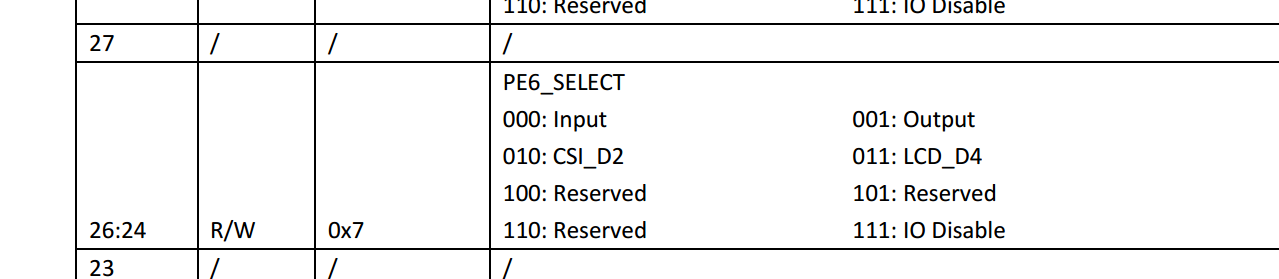
0x71就是pe6配置为output
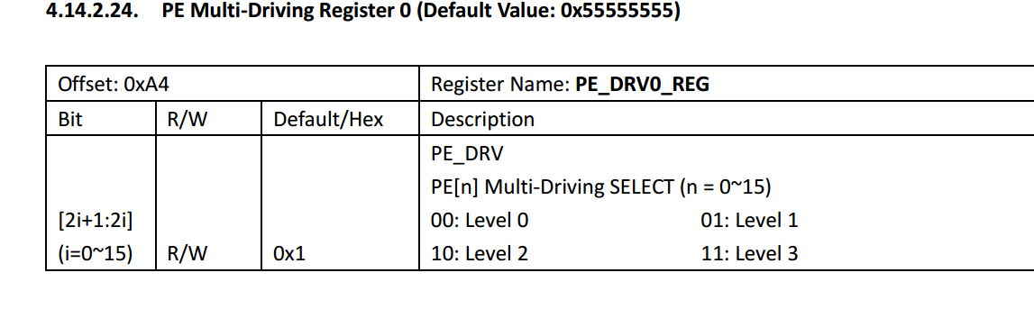
0x5就是0101,就是level1
pull就是disable。
5、找到问题原因
看配置也没有问题。把屏幕去掉,重新启动,看到现象和以前一样。那么就不是驱动能力这些电器属性造成的。
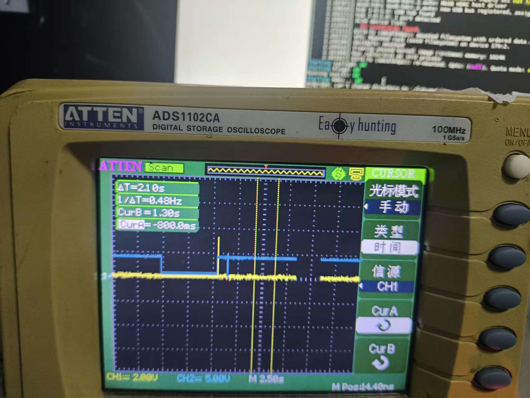
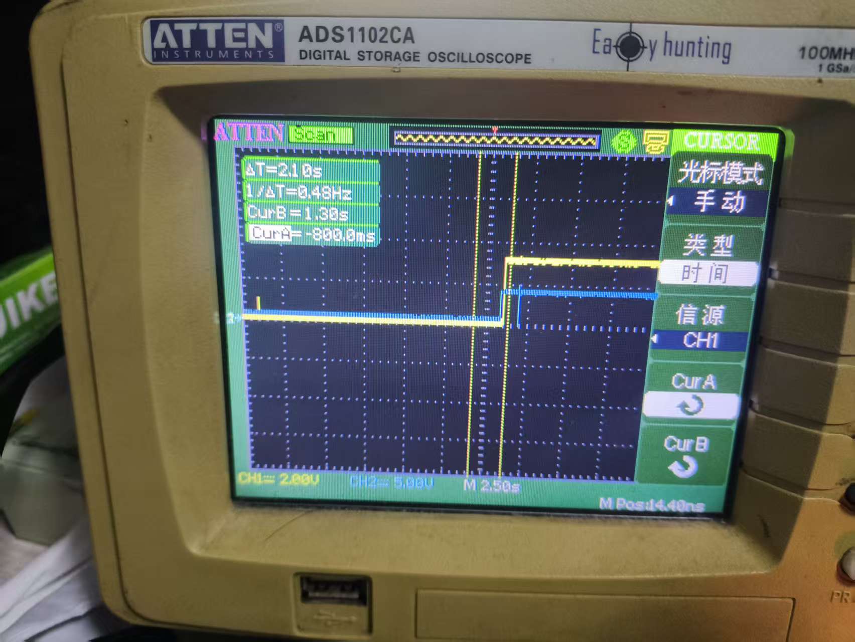
如图,黄色是reset,蓝色是dc。
看波形reset是被软件拉低了,然后一直没有恢复。下面就是分析fb_st7735r.c的初始化过程了。
============================st7735r初始化过程============================
fbtft_framebuffer_alloc
fbops->owner = dev->driver->owner;
fbops->fb_read = fb_sys_read;
fbops->fb_write = fbtft_fb_write;
fbops->fb_fillrect = fbtft_fb_fillrect;
fbops->fb_copyarea = fbtft_fb_copyarea;
fbops->fb_imageblit = fbtft_fb_imageblit;
fbops->fb_setcolreg = fbtft_fb_setcolreg;
fbops->fb_blank = fbtft_fb_blank;
/* default fbtft operations */
par->fbtftops.write = fbtft_write_spi;
par->fbtftops.read = fbtft_read_spi;
par->fbtftops.write_vmem = fbtft_write_vmem16_bus8;
par->fbtftops.write_register = fbtft_write_reg8_bus8;
par->fbtftops.set_addr_win = fbtft_set_addr_win;
par->fbtftops.reset = fbtft_reset;
par->fbtftops.mkdirty = fbtft_mkdirty;
par->fbtftops.update_display = fbtft_update_display;
if (display->backlight)
par->fbtftops.register_backlight = fbtft_register_backlight;
fbtft_reset() 发现该函数是这样写的:
cpp
static void fbtft_reset(struct fbtft_par *par)
{
	if (!par->gpio.reset)
		return;

	fbtft_par_dbg(DEBUG_RESET, par, "%s()\n", __func__);

	gpiod_set_value_cansleep(par->gpio.reset, 1);
	usleep_range(20, 40);
	gpiod_set_value_cansleep(par->gpio.reset, 0);
	msleep(120);

	gpiod_set_value_cansleep(par->gpio.cs, 1);  /* Activate chip */
}
字面意思是reset脚先置高,等一段时间后,再置低。
st7735我太熟悉了,正常启动流程正好相反,是先将reset拉低,再拉高。因为离开函数前,是手动设置为低,所以符合之前看到的波形。
所以修改为:
cpp
static void fbtft_reset(struct fbtft_par *par)
{
	if (!par->gpio.reset)
		return;

	fbtft_par_dbg(DEBUG_RESET, par, "%s()\n", __func__);

	//gpiod_set_value_cansleep(par->gpio.reset, 1);
	gpiod_set_value_cansleep(par->gpio.reset, 0);
	usleep_range(20, 40);
	//gpiod_set_value_cansleep(par->gpio.reset, 0);
	gpiod_set_value_cansleep(par->gpio.reset, 1);
	msleep(120);

	gpiod_set_value_cansleep(par->gpio.cs, 1);  /* Activate chip */
}
获得波形如下(可以看到reset信号已经正常了):
输入以下命令:
dd if=urandom of=fb0 bs=1k count=40
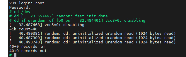
可得图片:
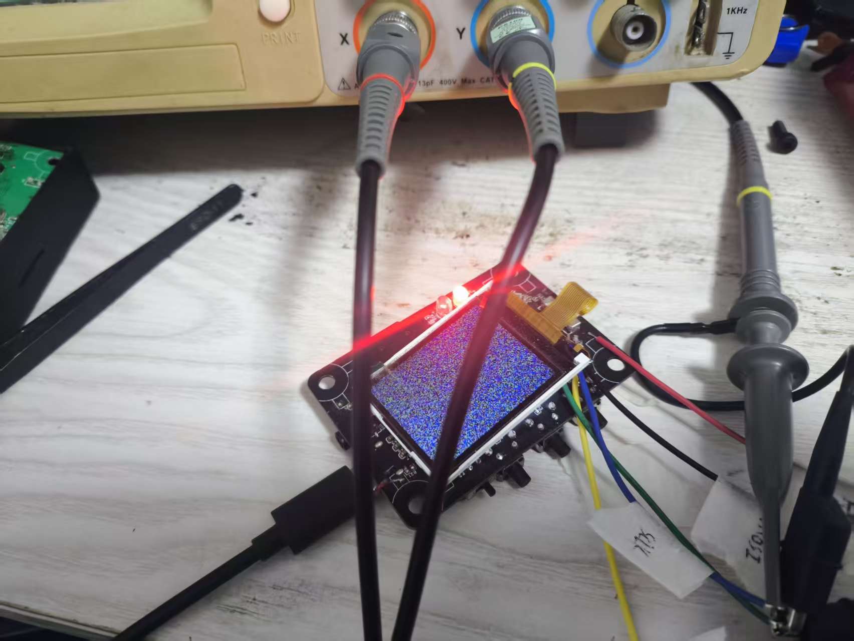
看到从黑屏,刷到了随机点。这样一来,一切都正常了。
=======================================================================
三、修改显示偏移
什么,你说屏幕有白边,那就改这里:
cpp
#define X_OFFSET	(1U)
#define Y_OFFSET	(2U)
static void set_addr_win(struct fbtft_par *par, int xs, int ys, int xe, int ye)
{
	xs	+= X_OFFSET;xe	+= X_OFFSET;
	ys	+= Y_OFFSET;ye	+= Y_OFFSET;

	write_reg(par, MIPI_DCS_SET_COLUMN_ADDRESS,
		  xs >> 8, xs & 0xFF, xe >> 8, xe & 0xFF);

	write_reg(par, MIPI_DCS_SET_PAGE_ADDRESS,
		  ys >> 8, ys & 0xFF, ye >> 8, ye & 0xFF);

	write_reg(par, MIPI_DCS_WRITE_MEMORY_START);
}
四、设备树备份:
/*
* Copyright (C) 2016 Icenowy Zheng <icenowy@aosc.xyz>
*
* This file is dual-licensed: you can use it either under the terms
* of the GPL or the X11 license, at your option. Note that this dual
* licensing only applies to this file, and not this project as a
* whole.
*
* a) This file is free software; you can redistribute it and/or
* modify it under the terms of the GNU General Public License as
* published by the Free Software Foundation; either version 2 of the
* License, or (at your option) any later version.
*
* This file is distributed in the hope that it will be useful,
* but WITHOUT ANY WARRANTY; without even the implied warranty of
* MERCHANTABILITY or FITNESS FOR A PARTICULAR PURPOSE. See the
* GNU General Public License for more details.
*
* Or, alternatively,
*
* b) Permission is hereby granted, free of charge, to any person
* obtaining a copy of this software and associated documentation
* files (the "Software"), to deal in the Software without
* restriction, including without limitation the rights to use,
* copy, modify, merge, publish, distribute, sublicense, and/or
* sell copies of the Software, and to permit persons to whom the
* Software is furnished to do so, subject to the following
* conditions:
*
* The above copyright notice and this permission notice shall be
* included in all copies or substantial portions of the Software.
*
* THE SOFTWARE IS PROVIDED "AS IS", WITHOUT WARRANTY OF ANY KIND,
* EXPRESS OR IMPLIED, INCLUDING BUT NOT LIMITED TO THE WARRANTIES
* OF MERCHANTABILITY, FITNESS FOR A PARTICULAR PURPOSE AND
* NONINFRINGEMENT. IN NO EVENT SHALL THE AUTHORS OR COPYRIGHT
* HOLDERS BE LIABLE FOR ANY CLAIM, DAMAGES OR OTHER LIABILITY,
* WHETHER IN AN ACTION OF CONTRACT, TORT OR OTHERWISE, ARISING
* FROM, OUT OF OR IN CONNECTION WITH THE SOFTWARE OR THE USE OR
* OTHER DEALINGS IN THE SOFTWARE.
*/
/dts-v1/;
#include "sun8i-v3s.dtsi"
#include "sunxi-common-regulators.dtsi"
/ {
model = "Lichee Pi Zero";
compatible = "licheepi,licheepi-zero", "allwinner,sun8i-v3s";
aliases {
serial0 = &uart0;
serial2 = &uart2;
};
chosen {
stdout-path = "serial2:115200n8";
};
};
&mmc0 {
broken-cd;
bus-width = <4>;
vmmc-supply = <®_vcc3v3>;
status = "okay";
};
&uart0 {
pinctrl-0 = <&uart0_pb_pins>;
pinctrl-names = "default";
status = "okay";
};
&uart2 {
pinctrl-0 = <&uart2_pb_pins>;
pinctrl-names = "default";
status = "okay";
};
&usb_otg {
dr_mode = "otg";
status = "okay";
};
&usbphy {
usb0_id_det-gpios = <&pio 5 6 GPIO_ACTIVE_HIGH>;
status = "okay";
};
&codec {
allwinner,audio-routing =
"Headphone", "HP",
"Headphone", "HPCOM",
"MIC1", "Mic",
"Mic", "HBIAS";
status = "okay";
};
&ohci0 {
status = "okay";
};
&ehci0 {
status = "okay";
};
&spi0 {
status = "okay";
pinctrl-names = "default";
pinctrl-0 = <&spi0_pins>;
cs-gpios = <0>;
st7735r@0{
compatible = "sitronix,st7735r";
reg = <0x0>;
status = "okay";
spi-max-frequency = <48000000>;
spi-cpol;
spi-cpha;
fps = <60>;
buswidth = <8>;
//pinctrl-names = "default";
//pinctrl-0 = <&tft_lcd_pins>;
dc-gpios = <&pio 4 5 GPIO_ACTIVE_HIGH>; // PE5
reset-gpios = <&pio 4 6 GPIO_ACTIVE_LOW>; // PE6
debug = <0x0>;
rotate = <90>;
};
};