以下的移植过程都是基于野火的 S T M 32 H 750 X B H 6 STM32H750XBH6 STM32H750XBH6的开发板硬件,如图1和图2所示,具体野火的链接在这里https://doc.embedfire.com/products/link/zh/latest/mcu/stm32/stm32h750_h743_pro.html。
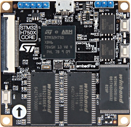
图1.
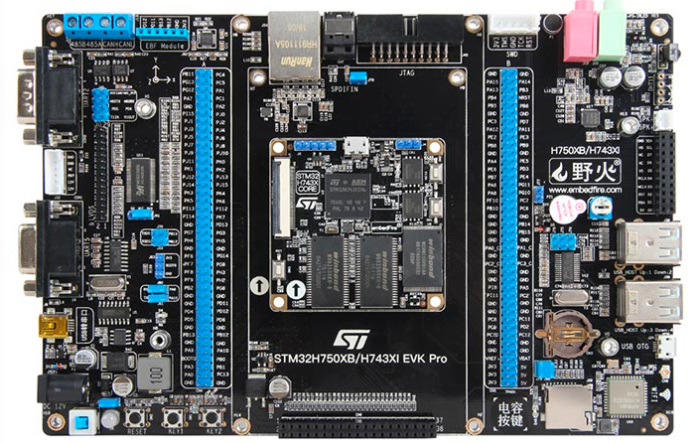
图2.
硬件有了之后我们再来看看软件,我们先准备一个 H 7 H7 H7的工程,也可以自己建立,自己建立可以参考这里https://blog.csdn.net/caoleiwe/article/details/126154021?spm=1011.2415.3001.5331。我这里直接取https://download.csdn.net/download/caoleiwe/88444283这里的工程作为开始。然后改一下相应的名字,添加一下 E T H ETH ETH模块的驱动,确保可以编译通过,正常下载,如图3所示。
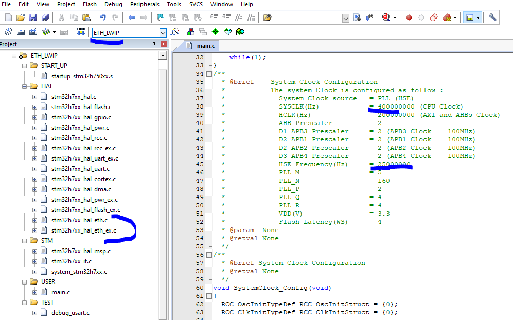
图3.
野火和正点原子针对 L W I P LWIP LWIP都有专门的一个合集来介绍,图4是野火的介绍文档,他们的介绍文档在移植的过程中会专门从 L W I P LWIP LWIP的官网(如图5所示,关于 L W I P LWIP LWIP的介绍网上很多介绍,我这里就不详细说明了)下载 L W I P LWIP LWIP的源码,但是我这里没有从 L W I P LWIP LWIP的官网下载 L W I P LWIP LWIP的源码,我这里直接使用的是 S T M 32 C u b e H 7 STM32Cube H7 STM32CubeH7里面的源码,如图6所示。

图4.
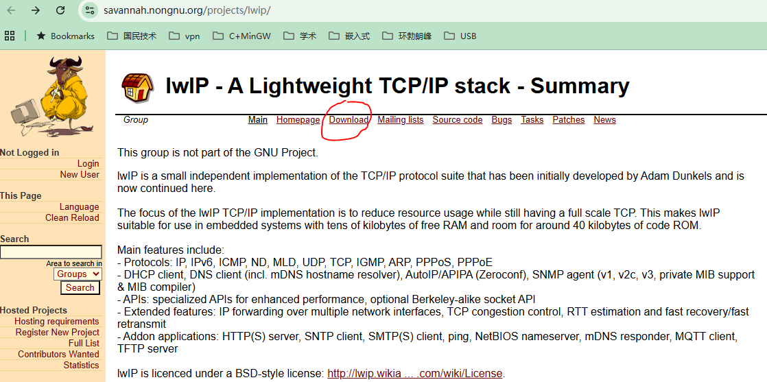
图5.
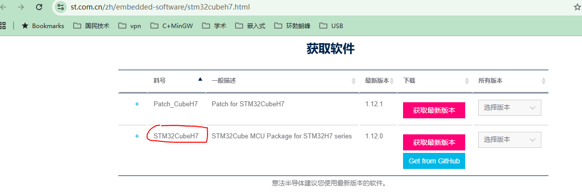
图6.
S T M 32 C u b e H 7 STM32Cube H7 STM32CubeH7里面的 L W I P LWIP LWIP的源码的位置如图7所示。这里我们只需要图7中下划红线的文件夹里面的代码就可以了,关于 L W I P LWIP LWIP的源码里面各个文件夹以及文件的介绍看看图4中的野火的文档就可以了。从图8可以看出这里使用的 L W I P LWIP LWIP的版本是 2.1.2 2.1.2 2.1.2,接着我们新建一个 l w i p lwip lwip文件夹并将图7中需要的源码放进去并放到工程文件夹里面去,如图9所示。
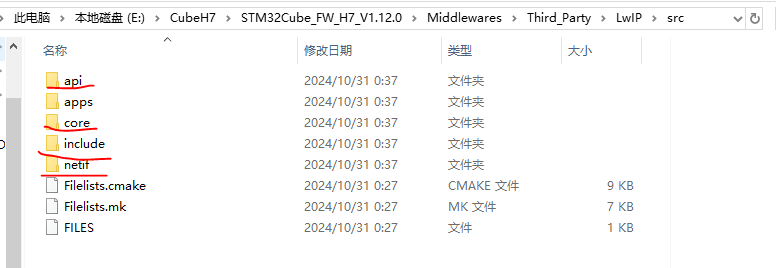
图7.
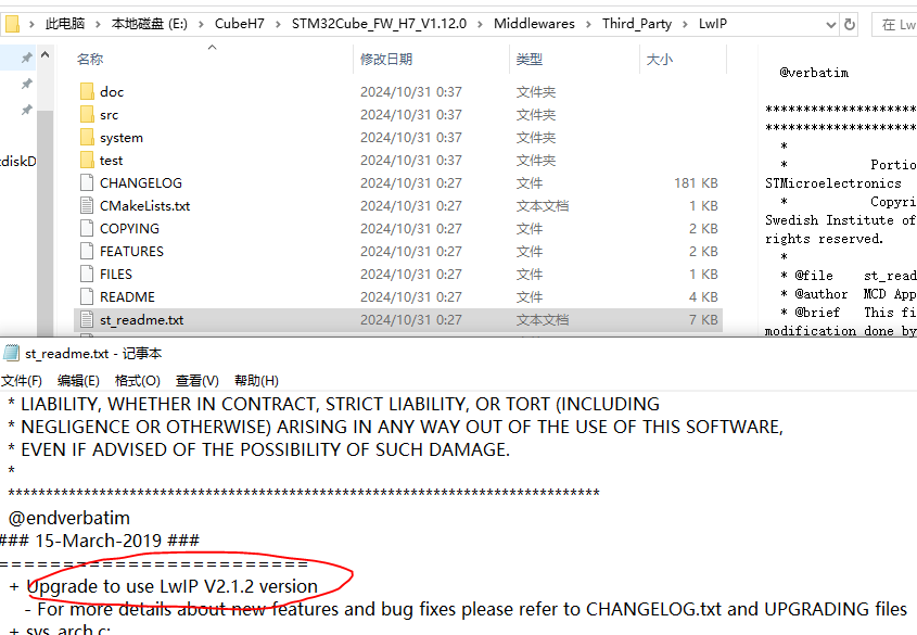
图8.
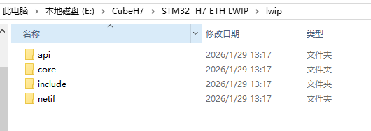
图9.
接着我们把图9中的源码和工程联系起来,如图10所示,编译之后现实缺少头文件 l w i p o p t s . h lwipopts.h lwipopts.h,这个头文件是用来对 L W I P LWIP LWIP协议栈进行剪裁的,是否需要某些功能以及大小可以通过在这个头文件中的不同宏定义来实现,图4中的野火的文档有更详细的介绍。这里我们直接从图11的 S T M 32 C u b e H 7 STM32Cube H7 STM32CubeH7里面的一个例子中找到该头文件然后放到我们在图12的工程目录里面再编译。
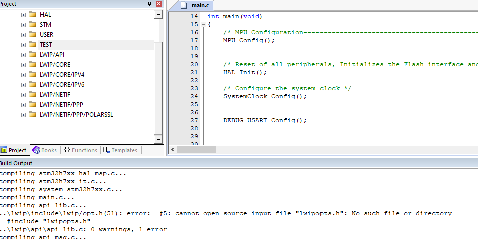
图10.
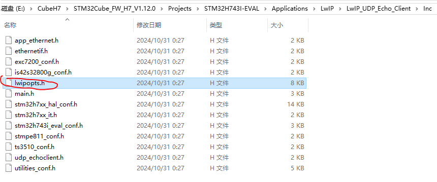
图11.
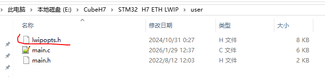
图12.
结果又显示缺少头文件,这时我们把图15中的 s y s t e m system system文件夹放到工程目录,如图14所示,然后再编译。这里别忘了如图16的包含头文件路径添加。
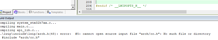
图13.
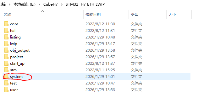
图14.
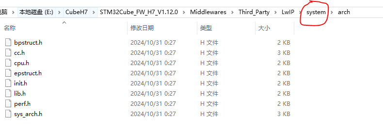
图15.
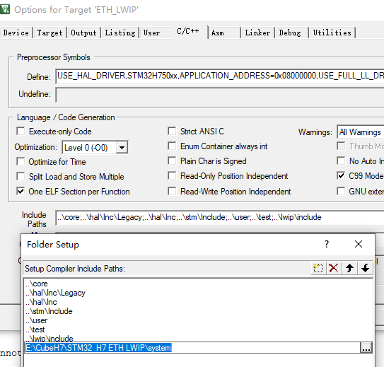
图16.
结果又显示图17的错误,图17中红圈中的三个错误的原因是某种功能需要这三个底层函数,但是我们这里没有实现,但是我们这里暂时也用不到这个功能,因此直接把 s l i p i f . c slipif.c slipif.c这个文件从我们的工程编译目录中删除即可,对于蓝圈中的错误是因为 L W I P LWIP LWIP协议栈中的 s y s _ n o w sys\_now sys_now时间基准函数没有实现,我们这里实现一下,然后放到工程文件中即可,如下所示。再编译之后就没有错误了。
c
/**
  * @brief  Returns the current time in milliseconds
  *         when LWIP_TIMERS == 1 and NO_SYS == 1
  * @param  None
  * @retval Current Time value
  */
uint32_t sys_now(void)
{
  return HAL_GetTick();
} 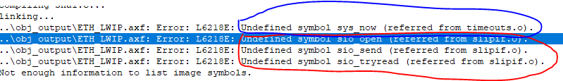
图17.
我们可以看到野火的以太网的 P H Y PHY PHY芯片使用的是 L A N 8720 A LAN8720A LAN8720A 且引脚 L E D 2 / n I N T S E L LED2/nINTSEL LED2/nINTSEL接地了,因此引脚 n I N T / R E F C L K O nINT/REFCLKO nINT/REFCLKO用于参考时钟输出而不是用来作为中断输出,因此 X T A L 1 XTAL1 XTAL1和 X T A L 2 XTAL2 XTAL2引脚接了一个25 M H Z MHZ MHZ的晶振用来在引脚 n I N T / R E F C L K O nINT/REFCLKO nINT/REFCLKO输出50 M H Z MHZ MHZ给 S T M 32 H 750 X B H 6 STM32H750XBH6 STM32H750XBH6的ETH模块,如图18,19,20,21所示。从图18中可以看出引脚 P H Y A D 0 PHYAD0 PHYAD0没有接低或高,但是它的内部有下拉,因此 L A N 8720 A LAN8720A LAN8720A 的访问地址为0。我有个疑问是只有一个引脚 P H Y A D 0 PHYAD0 PHYAD0的话,那么 L A N 8720 A LAN8720A LAN8720A 的访问地址只能是0或1,如果我想把 L A N 8720 A LAN8720A LAN8720A 的访问地址配置为大于1的情况怎么办?
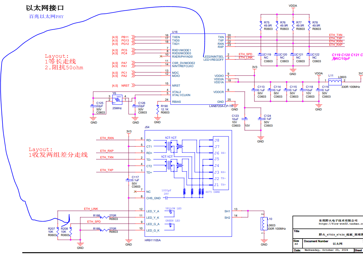
图18.
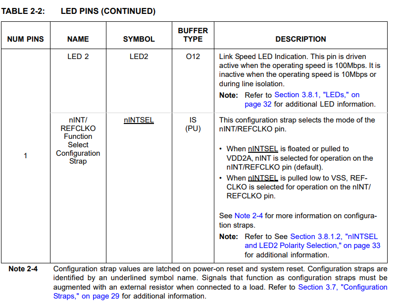
图19.
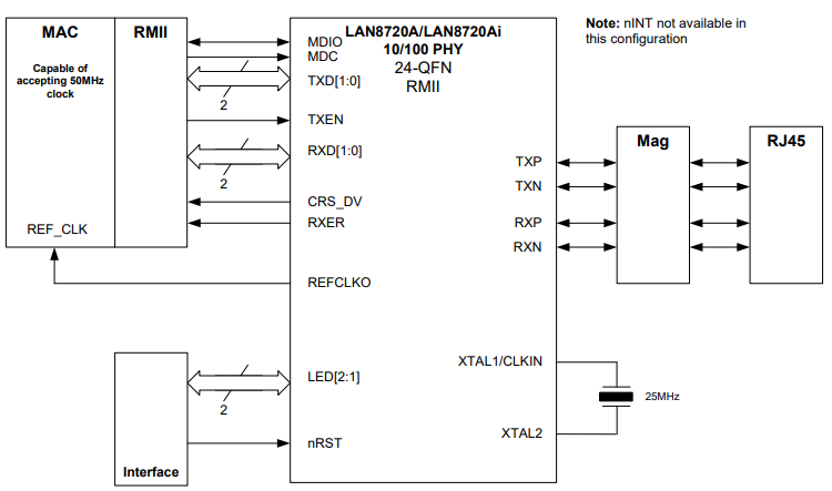
图20.
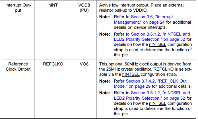
图21.
因为这里的移植只是简单的可以实现利用电脑可以利用 p i n g ping ping命令ping通开发板以及利用 D H C P DHCP DHCP协议可以为开发板分配 I P IP IP地址功能,因此这里首先将图22和图23里面的两个文件复制过来,再在这两个文件的基础上进行剪裁。同样将图24中的这两个文件改名为 l a n 8720 a lan8720a lan8720a之后再复制过来并进行修改。
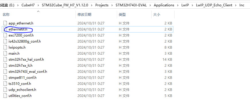
图22.
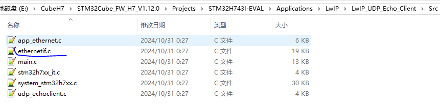
图23.
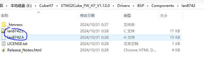
图24.
l a n 8720 a . c lan8720a.c lan8720a.c和 l a n 8720 a . h lan8720a.h lan8720a.h这两个文件主要是用来配置 L A N 8720 A LAN8720A LAN8720A这个 P H Y PHY PHY芯片的一些接口,还是比较容易实现的,其实就是调用 S T M 32 STM32 STM32的读写 P H Y PHY PHY芯片的寄存器的接口来操作配置 L A N 8720 A LAN8720A LAN8720A这个 P H Y PHY PHY芯片的参数。
c
/**
  * @brief  Initialize the lan8720a speed and duplex
  * @param  none.
  * @retval 1 if OK
  *         0 if FAILED
  */
int32_t LAN8720A_Init()
{
    uint32_t r_loop_num =10000;
    uint32_t bsr_reg_value =0;
    if(LAN8720A_StartAutoNego()!=LAN8720A_STATUS_OK)
    {
       return 0;
    }
    while(r_loop_num!=0)
    {
        if(ETH_PHY_IO_ReadReg(PHY_ADDRESS, LAN8720A_BSR, &bsr_reg_value) >= 0)
        {
            bsr_reg_value &=(0x00000020);
            if(bsr_reg_value ==(0x00000020))
            {
                return 1;
            }
	    }
	    r_loop_num++;
	}
    return 0;
}
L A N 8720 A LAN8720A LAN8720A这个 P H Y PHY PHY芯片的参数可以手动单独配置,也可以通过这个 P H Y PHY PHY芯片和网络中的其他设备的 P H Y PHY PHY芯片自动协商完成。这种自动协商完全是物理层的行为,也就是 P H Y PHY PHY芯片这一层, S T M 32 STM32 STM32的 E T H ETH ETH模块处于数据链路层。 L A N 8720 A LAN8720A LAN8720A这个 P H Y PHY PHY芯片主要协商的是:是 100 M 100M 100M的通信速率还是 10 M 10M 10M的通信速率。是全双工模式,还是半双工模式,协商完成之后 L A N 8720 A LAN8720A LAN8720A这个 P H Y PHY PHY芯片的相应的状态位会根据协商的结果对应相应的值,比如假设协商完成之后是 100 M 100M 100M的通信速率,那么 L A N 8720 A LAN8720A LAN8720A这个 P H Y PHY PHY芯片的相应寄存器的状态位就会显示是 100 M 100M 100M的通信速率。当然也可以不选择自动协商,而是单独配置。我们这里的 D E M O DEMO DEMO选择的是自动协商,如以上 L A N 8720 A LAN8720A LAN8720A这个 P H Y PHY PHY芯片的初始化代码所示,这里先将图25中的 B C R BCR BCR寄存器第12个比特位置1(使能自动协商),然后等待图26中的 B S R BSR BSR寄存器第5个比特位置1(等待自动协商完成)。
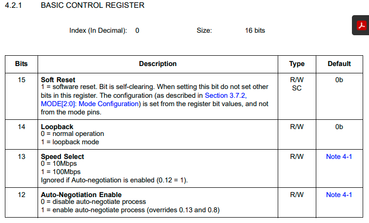
图25.
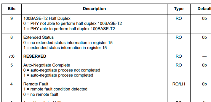
图26.
我直接把图23这个例子中的的以下两个接口复制到了 m a i n main main函数中,接口 N e t i f _ C o n f i g Netif\_Config Netif_Config的主要作用是配置了协议栈设备的 I P IP IP地址,网关和子网掩码(如果使能了 D H C P DHCP DHCP功能的话,定义宏 # d e f i n e L W I P _ D H C P 1 \#define\quad LWIP\_DHCP\quad 1 #defineLWIP_DHCP1,路由器会自动分配 I P IP IP地址给开发板),接口 N e t i f _ C o n f i g Netif\_Config Netif_Config里面的接口 n e t i f _ a d d netif\_add netif_add的主要作用相当于是把 L W I P LWIP LWIP协议栈(软件)和我们 S T M 32 STM32 STM32的 E T H ETH ETH模块(硬件)联系了起来,因为 L W I P LWIP LWIP协议栈(软件)不仅仅可以用于这里的 S T M 32 STM32 STM32的 E T H ETH ETH模块(硬件),也可以用于其他实现了数据链路层的硬件,具体详细的可以去图4的野火的手册的第4章去了解。接口 E t h e r n e t _ L i n k _ P e r i o d i c _ H a n d l e Ethernet\_Link\_Periodic\_Handle Ethernet_Link_Periodic_Handle的作用是每隔一定时间去检查 L A N 8720 A LAN8720A LAN8720A这个 P H Y PHY PHY芯片的参数(是 100 M 100M 100M的通信速率还是 10 M 10M 10M的通信速率,是全双工模式,还是半双工模式,因为有可能其他设备的 P H Y PHY PHY芯片发起了自动协商),如果有变化则我们会重新配置 S T M 32 STM32 STM32的 E T H ETH ETH模块的对应参数。接口 n e t i f _ s e t _ d e f a u l t netif\_set\_default netif_set_default的作用是当网络中有多个网卡接口时且没有指定采用那个网卡接口发送数据的时候,则采用该接口指定的默认网卡接口发送。接口 e t h e r n e t _ l i n k _ s t a t u s _ u p d a t e d ethernet\_link\_status\_updated ethernet_link_status_updated和接口 n e t i f _ s e t _ l i n k _ c a l l b a c k netif\_set\_link\_callback netif_set_link_callback的作用主要用于使能了 D H C P DHCP DHCP的 D E M O DEMO DEMO中。
c
/**
* @brief Ethernet Link periodic check
* @param netif
* @retval None
*/
void Ethernet_Link_Periodic_Handle(struct netif *netif)
{
/* Ethernet Link every 100ms */
if (HAL_GetTick() - EthernetLinkTimer >= 100)
{
EthernetLinkTimer = HAL_GetTick();
ethernet_link_check_state(netif);
}
}
/**
* @brief Setup the network interface
* @param None
* @retval None
*/
static void Netif_Config(void)
{
ip_addr_t ipaddr;
ip_addr_t netmask;
ip_addr_t gw;
#if LWIP_DHCP
ip_addr_set_zero_ip4(&ipaddr);
ip_addr_set_zero_ip4(&netmask);
ip_addr_set_zero_ip4(&gw);
#else
/* IP address default setting */
IP4_ADDR(&ipaddr, IP_ADDR0, IP_ADDR1, IP_ADDR2, IP_ADDR3);
IP4_ADDR(&netmask, NETMASK_ADDR0, NETMASK_ADDR1 , NETMASK_ADDR2, NETMASK_ADDR3);
IP4_ADDR(&gw, GW_ADDR0, GW_ADDR1, GW_ADDR2, GW_ADDR3);
#endif
/* add the network interface */
netif_add(&gnetif, &ipaddr, &netmask, &gw, NULL, ðernetif_init, ðernet_input);
/* Registers the default network interface */
netif_set_default(&gnetif);
//#if LWIP_DHCP
ethernet_link_status_updated(&gnetif);
netif_set_link_callback(&gnetif, ethernet_link_status_updated);
//#endif
}e t h e r n e t i f . c ethernetif.c ethernetif.c和 e t h e r n e t i f . h ethernetif.h ethernetif.h这两个文件的改动不是很大,只是做了一些小的修改,然后把不需要的功能接口都删除了。我们来看看其中比较关键的一些部分。
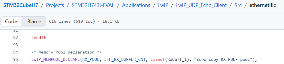
图27.
c
typedef struct
{
  struct pbuf_custom pbuf_custom;
  uint8_t buff[(ETH_RX_BUFFER_SIZE + 31) & ~31] __ALIGNED(32);
} RxBuff_t;
c
/** Main packet buffer struct */
struct pbuf {
  /** next pbuf in singly linked pbuf chain */
  struct pbuf *next;

  /** pointer to the actual data in the buffer */
  void *payload;

  /**
   * total length of this buffer and all next buffers in chain
   * belonging to the same packet.
   *
   * For non-queue packet chains this is the invariant:
   * p->tot_len == p->len + (p->next? p->next->tot_len: 0)
   */
  u16_t tot_len;

  /** length of this buffer */
  u16_t len;

  /** a bit field indicating pbuf type and allocation sources
      (see PBUF_TYPE_FLAG_*, PBUF_ALLOC_FLAG_* and PBUF_TYPE_ALLOC_SRC_MASK)
    */
  u8_t type_internal;

  /** misc flags */
  u8_t flags;

  /**
   * the reference count always equals the number of pointers
   * that refer to this pbuf. This can be pointers from an application,
   * the stack itself, or pbuf->next pointers from a chain.
   */
  LWIP_PBUF_REF_T ref;

  /** For incoming packets, this contains the input netif's index */
  u8_t if_idx;
};

/** Prototype for a function to free a custom pbuf */
typedef void (*pbuf_free_custom_fn)(struct pbuf *p);

/** A custom pbuf: like a pbuf, but following a function pointer to free it. */
struct pbuf_custom {
  /** The actual pbuf */
  struct pbuf pbuf;
  /** This function is called when pbuf_free deallocates this pbuf(_custom) */
  pbuf_free_custom_fn custom_free_function;
};
图27声明了一个内存池(详细的介绍可以查看图4的野火的手册的第5章去了解),我们经过一系列的预处理之后可以得到下面的结果
c
  u8_t memp_memory_RX_POOL_base[(12) * (1056) +3]
  static struct memp *memp_tab_RX_POOL;

  const struct memp_desc memp_RX_POOL =
  {
    1056,
    12,
    memp_memory_RX_POOL_base,
    &memp_tab_RX_POOL
  };
其实就是定义了一个内存池描述符并初始化了,内存池描述的结构体如下所示,但是按照图27中的工程里面的配置,只有图28中的4个元素。内存池初始化完成之后如图29所示,图29里面的next指针其实就是结构体struct pbuf_custom里面的结构体元素struct pbuf 的指针元素next。图30中蓝色圈里面的代码是初始化内存池的。
c
/** Memory pool descriptor */
struct memp_desc {
#if defined(LWIP_DEBUG) || MEMP_OVERFLOW_CHECK || LWIP_STATS_DISPLAY
  /** Textual description */
  const char *desc;
#endif /* LWIP_DEBUG || MEMP_OVERFLOW_CHECK || LWIP_STATS_DISPLAY */
#if MEMP_STATS
  /** Statistics */
  struct stats_mem *stats;
#endif

  /** Element size */
  u16_t size;

#if !MEMP_MEM_MALLOC
  /** Number of elements */
  u16_t num;

  /** Base address */
  u8_t *base;

  /** First free element of each pool. Elements form a linked list. */
  struct memp **tab;
#endif /* MEMP_MEM_MALLOC */
}; 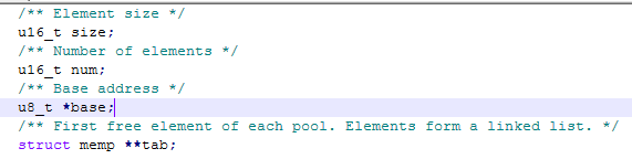
图28.
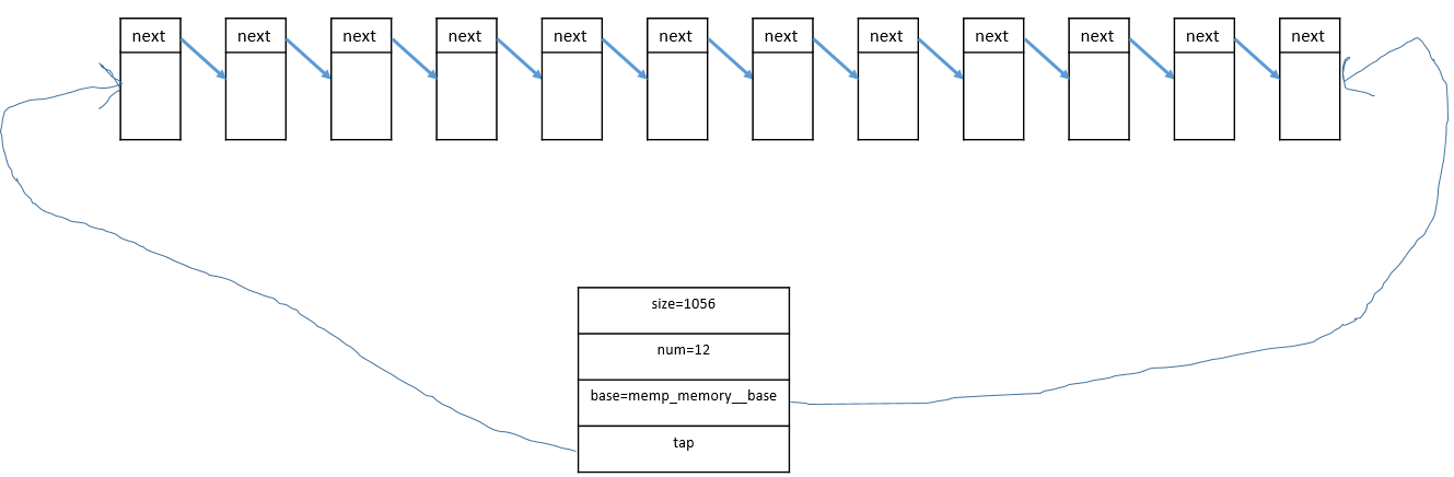
图29.
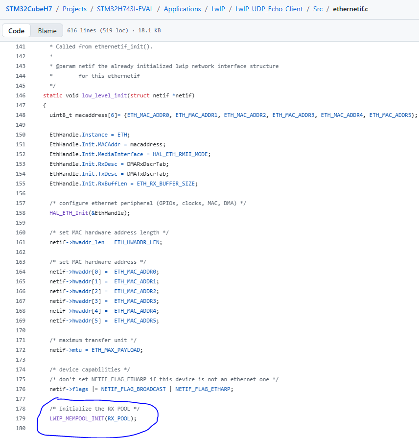
图30.
图31中的函数在刚刚初始化的内存池中取出来了一个内存块,图31中的函数的调用流程是图32,图33,图34,图35。
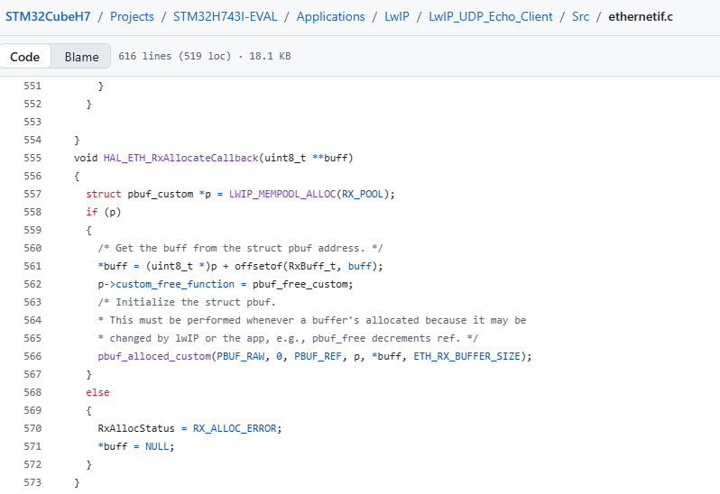
图31.
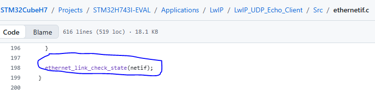
图32.
图33.
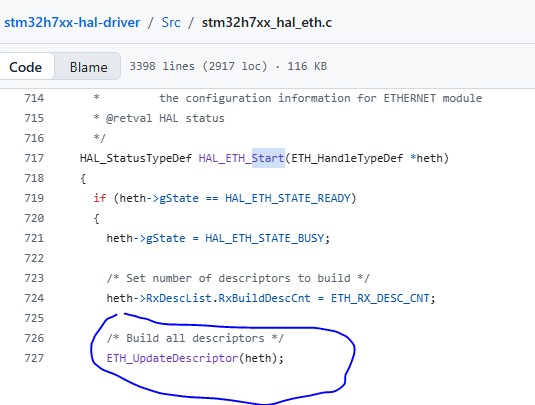
图34.
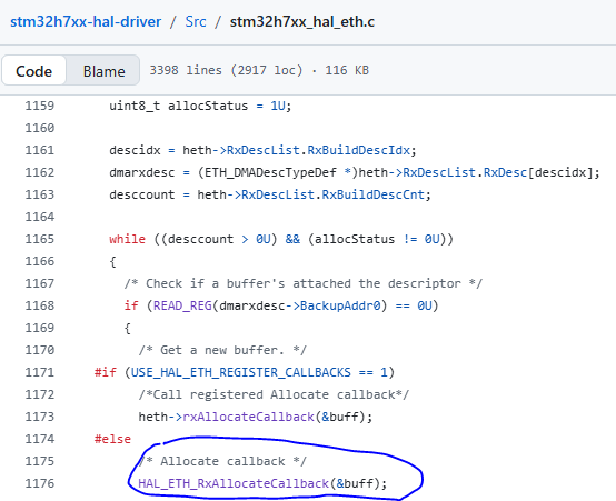
图35.
图31中的函数在刚刚初始化的内存池中取出来了一个内存块,取完之后如图36所示。取完这个内存块的地址会被偏移 s t r u c t p b u f _ c u s t o m struct\quad pbuf\_custom structpbuf_custom结构体的大小(偏移之后才是实际的存储数据的地址),然后再写入到 E T H ETH ETH的接收描述符用于存储接收到的数据。
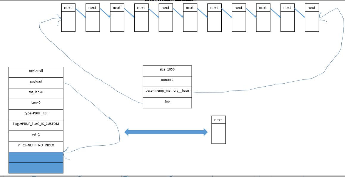
图36.
下面的接口相对于图36中的接口反向偏移了 s t r u c t p b u f _ c u s t o m struct\quad pbuf\_custom structpbuf_custom结构体的大小(反向偏移之后才是实际指向 s t r u c t p b u f _ c u s t o m struct\quad pbuf\_custom structpbuf_custom结构体)。
c
void HAL_ETH_RxLinkCallback(void **pStart, void **pEnd, uint8_t *buff, uint16_t Length)
{
  struct pbuf **ppStart = (struct pbuf **)pStart;
  struct pbuf **ppEnd = (struct pbuf **)pEnd;
  struct pbuf *p = NULL;

  /* Get the struct pbuf from the buff address. */
  p = (struct pbuf *)(buff - offsetof(RxBuff_t, buff));
  p->next = NULL;
  p->tot_len = 0;
  p->len = Length;

  /* Chain the buffer. */
  if (!*ppStart)
  {
    /* The first buffer of the packet. */
    *ppStart = p;
  }
  else
  {
    /* Chain the buffer to the end of the packet. */
    (*ppEnd)->next = p;
  }
  *ppEnd  = p;

  /* Update the total length of all the buffers of the chain. Each pbuf in the chain should have its tot_len
   * set to its own length, plus the length of all the following pbufs in the chain. */
  for (p = *ppStart; p != NULL; p = p->next)
  {
    p->tot_len += Length;
  }

  /* Invalidate data cache because Rx DMA's writing to physical memory makes it stale. */
  SCB_InvalidateDCache_by_Addr((uint32_t *)buff, Length);
}
通过 E T H ETH ETH模块接收了一帧数据(可能跨越了多个描述符的buffer)之后(通过接口 l o w _ l e v e l _ i n p u t low\_level\_input low_level_input),然后通过接口 n e t i f − > i n p u t netif->input netif−>input(实际是 e t h e r n e t _ i n p u t ethernet\_input ethernet_input)a把数据包传送给上层协议处理。上层协议处理完之后会释放这个在图35中的接口中分配的内存区域。因为图35中的接口中分配的内存区域被初始化为 s t r u c t p b u f _ c u s t o m struct\quad pbuf\_custom structpbuf_custom类型,因此必须自己定义释放函数,如图37所示。图38也有说明。
c
/**
  * @brief This function is the ethernetif_input task, it is processed when a packet
  * is ready to be read from the interface. It uses the function low_level_input()
  * that should handle the actual reception of bytes from the network
  * interface. Then the type of the received packet is determined and
  * the appropriate input function is called.
  *
  * @param netif the lwip network interface structure for this ethernetif
  */
void ethernetif_input(struct netif *netif)
{
  struct pbuf *p = NULL;

    do
    {
      p = low_level_input( netif );
      if (p != NULL)
      {
        if (netif->input( p, netif) != ERR_OK )
        {
          pbuf_free(p);
        }
      }

    } while(p!=NULL);
} 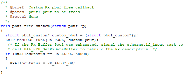
图37.
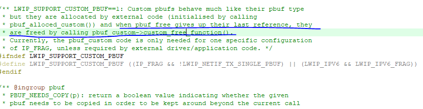
图38.
再来看一下 m a i n main main函数,如下所示, l w i p _ i n i t lwip\_init lwip_init是整个协议栈的初始化, N e t i f _ C o n f i g Netif\_Config Netif_Config前面有讲到, w h i l e while while死循环里面会等到 D M A C S R DMACSR DMACSR寄存器的第6个比特位置1(也就是相当于收到了一帧数据),接着去读这一帧数据然后把这一帧数据送给上层协议,如图39和40所示,这个标志位置起的条件是相应的中断使能位必须置1。接口 s y s _ c h e c k _ t i m e o u t s sys\_check\_timeouts sys_check_timeouts是超时的一些处理,接口 E t h e r n e t _ L i n k _ P e r i o d i c _ H a n d l e Ethernet\_Link\_Periodic\_Handle Ethernet_Link_Periodic_Handle前面有讲到过,接口 D H C P _ P e r i o d i c _ H a n d l e DHCP\_Periodic\_Handle DHCP_Periodic_Handle在使能 D H C P DHCP DHCP功能的时候会用到。
c
/**
  * @brief  The application entry point.
  * @retval int
  */
int main(void)
{
    /* MPU Configuration--------------------------------------------------------*/
    MPU_Config();
    /* Reset of all peripherals, Initializes the Flash interface and the Systick. */
    HAL_Init();
    /* Configure the system clock */
    SystemClock_Config();
    DEBUG_USART_Config();
    /* Initialize the LwIP stack */
    lwip_init();
    /* Configure the Network interface */
    Netif_Config();

	  debug_print("This is the ETH demo.\r\n");
    /* Infinite loop */
    while (1)
    {
			  if(ETH->DMACSR & (0x00000040))
				{
            /* Read a received packet from the Ethernet buffers and send it to the lwIP for handling */
            ethernetif_input(&gnetif);
					  ETH->DMACSR=0x00000040;
					  while(ETH->DMACSR & (0x00000040));
					  debug_print("T\r\n");
				}

      /* Handle timeouts */
      sys_check_timeouts();
      Ethernet_Link_Periodic_Handle(&gnetif);

#if LWIP_DHCP
      DHCP_Periodic_Handle(&gnetif);
#endif
    }
} 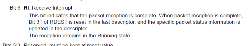
图39.
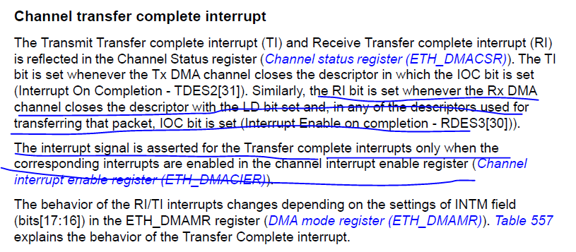
图40.
接下来我们将程序编译好下载到开发板,然后再配置一下开发板和我的电脑的 I P IP IP地址,网关地址和地址掩码等。如图41和42所示。
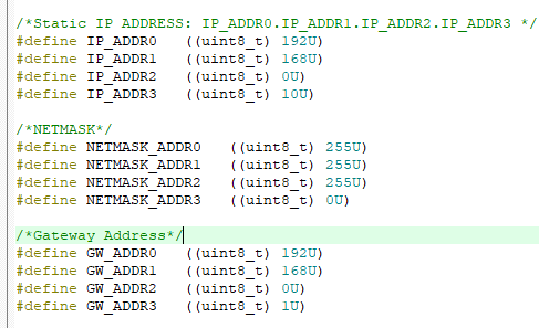
图41.
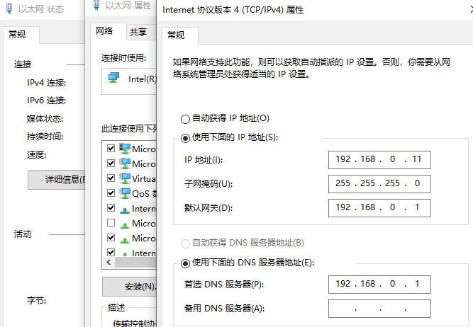
图42.
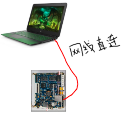
图43.
接下来我们将开发板和电脑用普通的网线连接起来(这里没有使能 D H C P DHCP DHCP功能),然后打开电脑( W i n 10 Win10 Win10)的命令行窗口,然后尝试去 p i n g ping ping开发板的 I P IP IP地址 192.168.0.10 192.168.0.10 192.168.0.10,看能否成功(即开发板可以会送数据给电脑),如果出现图44的结果则表明 p i n g ping ping成功。这里开发板和电脑用普通的网线连接起来之后电脑会发送很多的数据包(会一直断的打印大写字母 T T T,对应 m a i n main main函数中的 C C C语句 d e b u g _ p r i n t ( " T r n " ) ; debug\_print("T\\r\\n"); debug_print("Trn");),这些数据包是干啥的目前我也不懂,我这里的程序偶尔会出现小问题,就是开发板复位之后,打印几个大写字母 T T T之后就不打印了,不知道是程序哪里出了问题(进 d e b u g debug debug模式显示是进了 H a r d F a u l t HardFault HardFault),最后定位到是图45中的接口里面的语句造成的,具体原因未知,屏蔽之后似乎就好了。
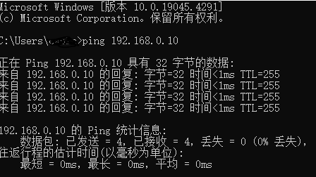
图44.
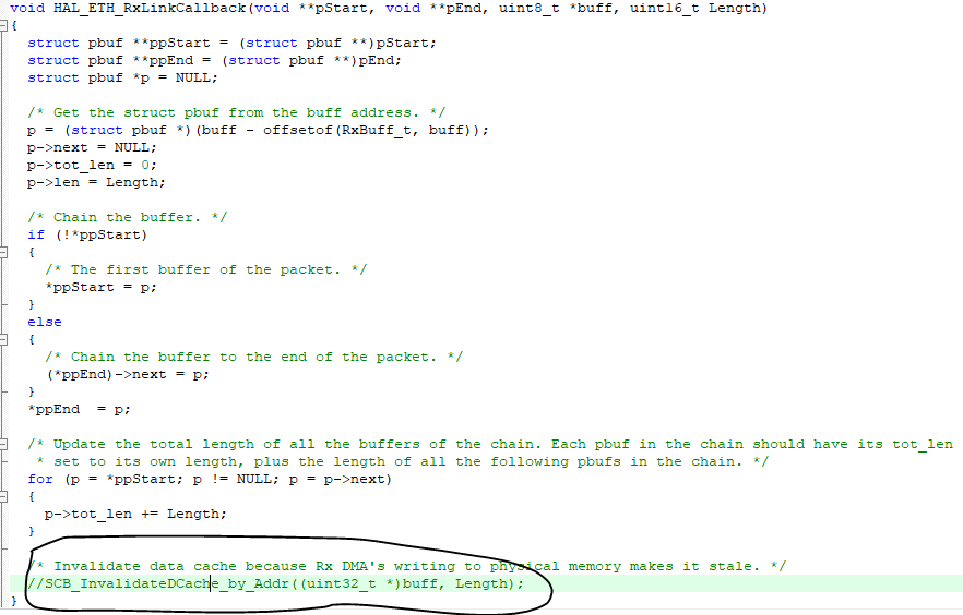
图45.
p i n g ping ping命令实际上是发送了4个 I C M P ICMP ICMP协议请求包,正常协议规定,如果通信成功的话,收到 I C M P ICMP ICMP协议请求包的设备需要返回 I C M P ICMP ICMP协议回送包(刚开始的时候电脑是不知道开发板的 M A C MAC MAC地址,即硬件地址的,因此电脑在发送 I C M P ICMP ICMP协议请求包之前会发送 A R P ARP ARP数据包来获取开发板的硬件地址,这里我们假设电脑已经知道了开发板的硬件地址),关于 A R P ARP ARP协议和 I C M P ICMP ICMP协议可以分别简单看下图46的谢希仁版的《计算机网络(第8版)》的第 4.2.4 4.2.4 4.2.4和 4.4 4.4 4.4小节。

图46.
从图47中可以看出一个 p i n g ping ping命令之后捕获的4个 I C M P ICMP ICMP协议请求包和对应的4个 I C M P ICMP ICMP协议会送包。
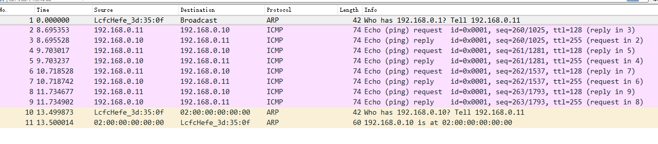
图47.
接下来我们简单看一下一个 I C M P ICMP ICMP协议请求包发送到开发版之后到返回到电脑的大概的一个流程。当有一个数据包到达开发板之后,首先会经过图48和图49中的接口,图49中的接口 n e t i f − > i n p u t ( p , n e t i f ) netif->input( p, netif) netif−>input(p,netif)其实就是接口 e t h e r n e t _ i n p u t ethernet\_input ethernet_input。
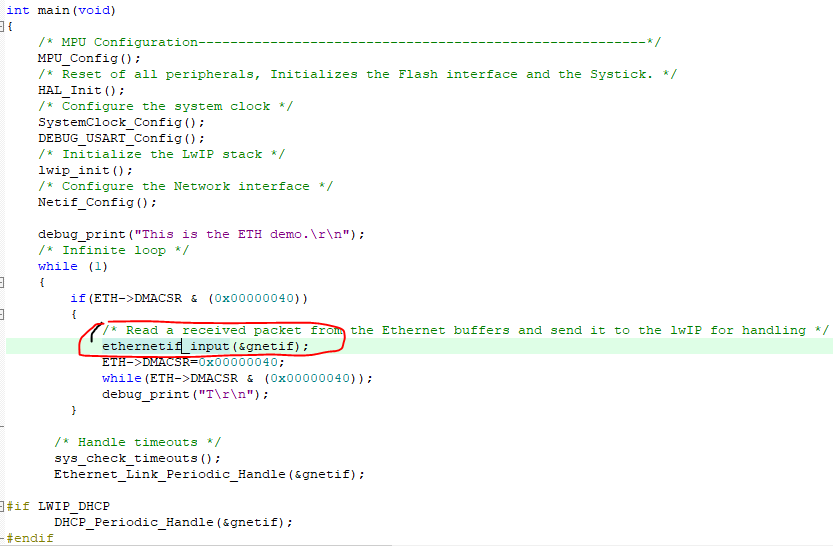
图48.
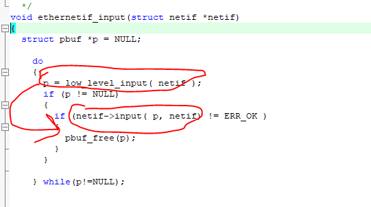
图49.
接下来数据包达到图50的两个红圈中的接口,接着进入接口 i p 4 _ i n p u t ip4\_input ip4_input里面的接口 i c m p i n p u t icmp_input icmpinput,如图51所示。
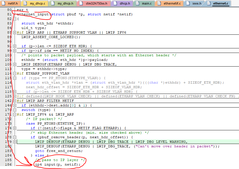
图50.
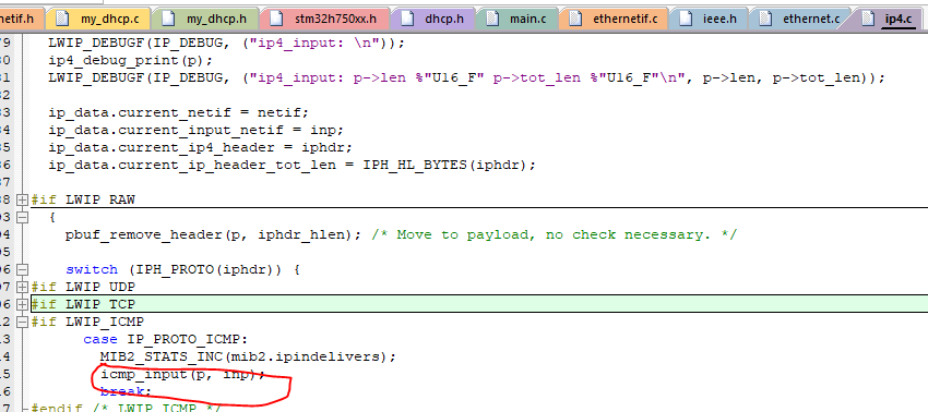
图51.
接着进入接口 i c m p i n p u t icmp_input icmpinput里面的接口 i p 4 _ o u t p u t _ i f ip4\_output\_if ip4_output_if,如图52所示。接着进入接口 i p 4 _ o u t p u t _ i f _ s r c ip4\_output\_if\_src ip4_output_if_src,如图53所示。接着进入接口 i p 4 _ o u t p u t _ i f _ s r c ip4\_output\_if\_src ip4_output_if_src里面的接口 n e t i f − > o u t p u t netif->output netif−>output,如图54所示。这时就发送一个 I C M P ICMP ICMP协议会送包给了电脑,这是因为接口 n e t i f − > o u t p u t netif->output netif−>output实际上就是我们自己定义的 S T M 32 STM32 STM32的 E T H ETH ETH模块的数据保发送接口 l o w _ l e v e l _ o u t p u t low\_level\_output low_level_output,如图55所示。
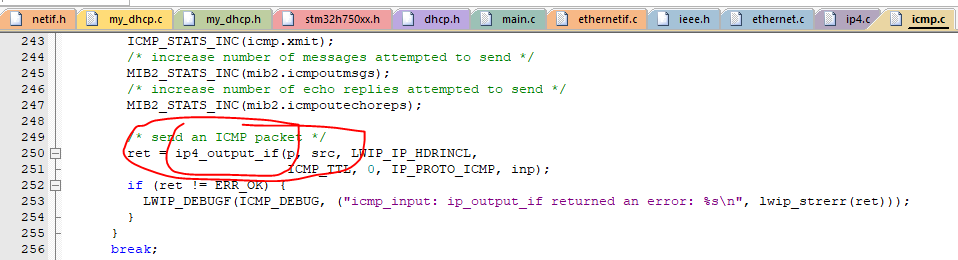
图52.
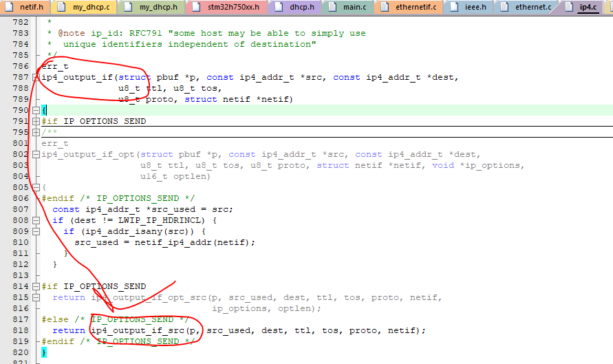
图53.
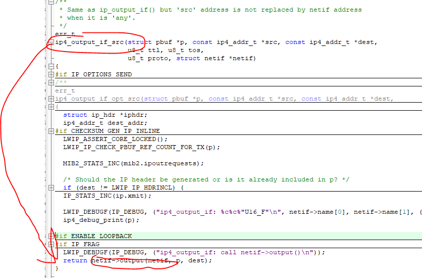
图54.
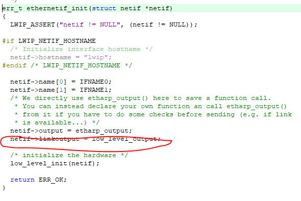
图55.
在上面的例子中的 I P IP IP地址,网关和子网掩码等都是直接配置好的,没有启用 D H C P DHCP DHCP功能(也就是 D H C P DHCP DHCP服务器自动给 D H C P DHCP DHCP客户端分配一个 I P IP IP地址,网关和子网掩码等,这里 D H C P DHCP DHCP服务器是路由器, D H C P DHCP DHCP客户端是开发板,这时硬件连线也和以前没有启用 D H C P DHCP DHCP功能的例子有些区别,如图56所示,因为电脑是没有 D H C P DHCP DHCP服务器功能的),如果需要启用 D H C P DHCP DHCP功能需要将宏 L W I P _ D H C P LWIP\_DHCP LWIP_DHCP的值定义为1,且添加如图57两个文件。
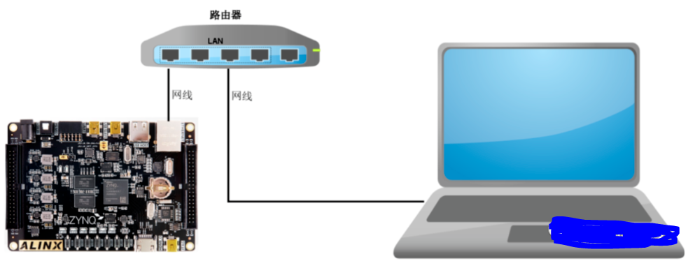
图56.
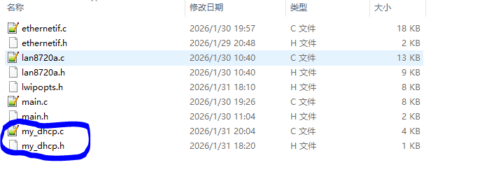
图57.
图57中的 m y _ d h c p . c my\_dhcp.c my_dhcp.c文件的主要内容如下,其实主要看 D H C P _ P r o c e s s DHCP\_Process DHCP_Process这个接口,刚开始的时候 D H C P _ s t a t e DHCP\_state DHCP_state为 D H C P _ O F F DHCP\_OFF DHCP_OFF,一般当开发板复位开机之后会调用接口 e t h e r n e t _ l i n k _ s t a t u s _ u p d a t e d ethernet\_link\_status\_updated ethernet_link_status_updated,如果 L W I P LWIP LWIP协议栈已经和 S T M 32 STM32 STM32的 E T H ETH ETH模块的建立了联系,那么这时 D H C P _ s t a t e DHCP\_state DHCP_state为 D H C P _ S T A R T DHCP\_START DHCP_START,这时会调用接口 d h c p _ s t a r t dhcp\_start dhcp_start来开启开发板向路由器请求分配 I P IP IP地址,网关和子网掩码等的过程,这时 D H C P _ s t a t e DHCP\_state DHCP_state为 D H C P _ W A I T _ A D D R E S S DHCP\_WAIT\_ADDRESS DHCP_WAIT_ADDRESS,这时会等待路由器分配,调用接口 d h c p _ s u p p l i e d _ a d d r e s s dhcp\_supplied\_address dhcp_supplied_address检查分配是否完成,如果超过一定的时间没有分配完成就将 I P IP IP地址,网关和子网掩码等配置为预先准备的值(通过调用接口 n e t i f _ s e t _ a d d netif\_set\_add netif_set_add),在 m a i n main main函数中的死循环中会不断调用接口 D H C P _ P e r i o d i c _ H a n d l e DHCP\_Periodic\_Handle DHCP_Periodic_Handle。
c
#define MAX_DHCP_TRIES  40
uint32_t DHCPfineTimer = 0;
uint8_t DHCP_state = DHCP_OFF;


/**
  * @brief  DHCP_Process_Handle
  * @param  None
  * @retval None
  */
void DHCP_Process(struct netif *netif)
{
  ip_addr_t ipaddr;
  ip_addr_t netmask;
  ip_addr_t gw;
  struct dhcp *dhcp;
  uint8_t iptxt[20];
#if LWIP_DHCP

  switch (DHCP_state)
  {
    case DHCP_START:
    {
      debug_print("  State: Looking for DHCP server ...\n");
      ip_addr_set_zero_ip4(&netif->ip_addr);
      ip_addr_set_zero_ip4(&netif->netmask);
      ip_addr_set_zero_ip4(&netif->gw);
      dhcp_start(netif);
      DHCP_state = DHCP_WAIT_ADDRESS;
    }
    break;

  case DHCP_WAIT_ADDRESS:
    {
      if (dhcp_supplied_address(netif))
      {
        DHCP_state = DHCP_ADDRESS_ASSIGNED;
        sprintf((char *)iptxt, "%s", ip4addr_ntoa(netif_ip4_addr(netif)));
        debug_print("IP address assigned by a DHCP server: %s\n", iptxt);
        sprintf((char *)iptxt, "%s", ip4addr_ntoa(netif_ip4_netmask(netif)));
        debug_print("NetMask assigned by a DHCP server: %s\n", iptxt);
        sprintf((char *)iptxt, "%s", ip4addr_ntoa(netif_ip4_gw(netif)));
        debug_print("GateWay assigned by a DHCP server: %s\n", iptxt);
      }
      else
      {
        dhcp = (struct dhcp *)netif_get_client_data(netif, LWIP_NETIF_CLIENT_DATA_INDEX_DHCP);

        /* DHCP timeout */
        if (dhcp->tries > MAX_DHCP_TRIES)
        {
          DHCP_state = DHCP_TIMEOUT;

          /* Static address used */
          IP_ADDR4(&ipaddr, IP_ADDR0 ,IP_ADDR1 , IP_ADDR2 , IP_ADDR3 );
          IP_ADDR4(&netmask, NETMASK_ADDR0, NETMASK_ADDR1, NETMASK_ADDR2, NETMASK_ADDR3);
          IP_ADDR4(&gw, GW_ADDR0, GW_ADDR1, GW_ADDR2, GW_ADDR3);
          netif_set_addr(netif, &ipaddr, &netmask, &gw);

          sprintf((char *)iptxt, "%s", ip4addr_ntoa(netif_ip4_addr(netif)));
          debug_print("DHCP Timeout !! \n");
          debug_print("Static IP address: %s\n", iptxt);
        }
      }
    }
    break;
  case DHCP_LINK_DOWN:
    {
      DHCP_state = DHCP_OFF;
      debug_print("The network cable is not connected \n");
    }
    break;
  default: break;
  }
#endif
}

/**
  * @brief  DHCP periodic check
  * @param  netif
  * @retval None
  */
void DHCP_Periodic_Handle(struct netif *netif)
{
#if LWIP_DHCP
  /* Fine DHCP periodic process every 500ms */
  if (HAL_GetTick() - DHCPfineTimer >= DHCP_FINE_TIMER_MSECS)
  {
    DHCPfineTimer =  HAL_GetTick();
    /* process DHCP state machine */
    DHCP_Process(netif);
  }
#endif
}

/**
  * @brief  Notify the User about the network interface config status
  * @param  netif: the network interface
  * @retval None
  */
void ethernet_link_status_updated(struct netif *netif)
{
  if (netif_is_link_up(netif))
  {
    /* Update DHCP state machine */
    DHCP_state = DHCP_START;
    uint8_t iptxt[20];
    sprintf((char *)iptxt, "%s", ip4addr_ntoa(netif_ip4_addr(netif)));
    debug_print("Static IP address: %s\n", iptxt);
    sprintf((char *)iptxt, "%s", ip4addr_ntoa(netif_ip4_netmask(netif)));
    debug_print("Static NetMask: %s\n", iptxt);
    sprintf((char *)iptxt, "%s", ip4addr_ntoa(netif_ip4_gw(netif)));
    debug_print("Static GateWay: %s\n", iptxt);
  }
  else
  {
    /* Update DHCP state machine */
    DHCP_state = DHCP_LINK_DOWN;
    debug_print("The network cable is not connected\r\n");
  }
}
关于 D H C P DHCP DHCP协议的简单描述可以参考图46的谢希仁版的《计算机网络(第8版)》的第 6.6 6.6 6.6小节。这里下载完程序复位然后分配的结果如图58所示(开发板已经连接到了路由器)。到这里我觉得你也可以完整的单独的来一次移植了,如果你觉得有困难,可以向我要源代码。
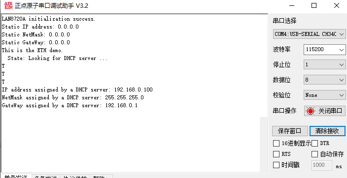
图58.