一、 前言
很高兴能参加本次瑞萨 AI 挑战赛。我收到的硬件是 FPB-RA6E2(Fast Prototyping Board)。这款板子搭载了高性能的 RA6E2 系列单片机,其 200MHz 的 Cortex-M33 内核在边缘 AI 推理方面非常令人期待。本篇将记录我的开箱体验及开发环境的搭建过程。
瑞萨官网:www.renesas.cn
二、 硬件开箱
FPB-RA6E2 的设计非常紧凑,板载资源丰富:
核心 MCU: R7FA6E27BB3CFP (Cortex-M33, 200MHz)。
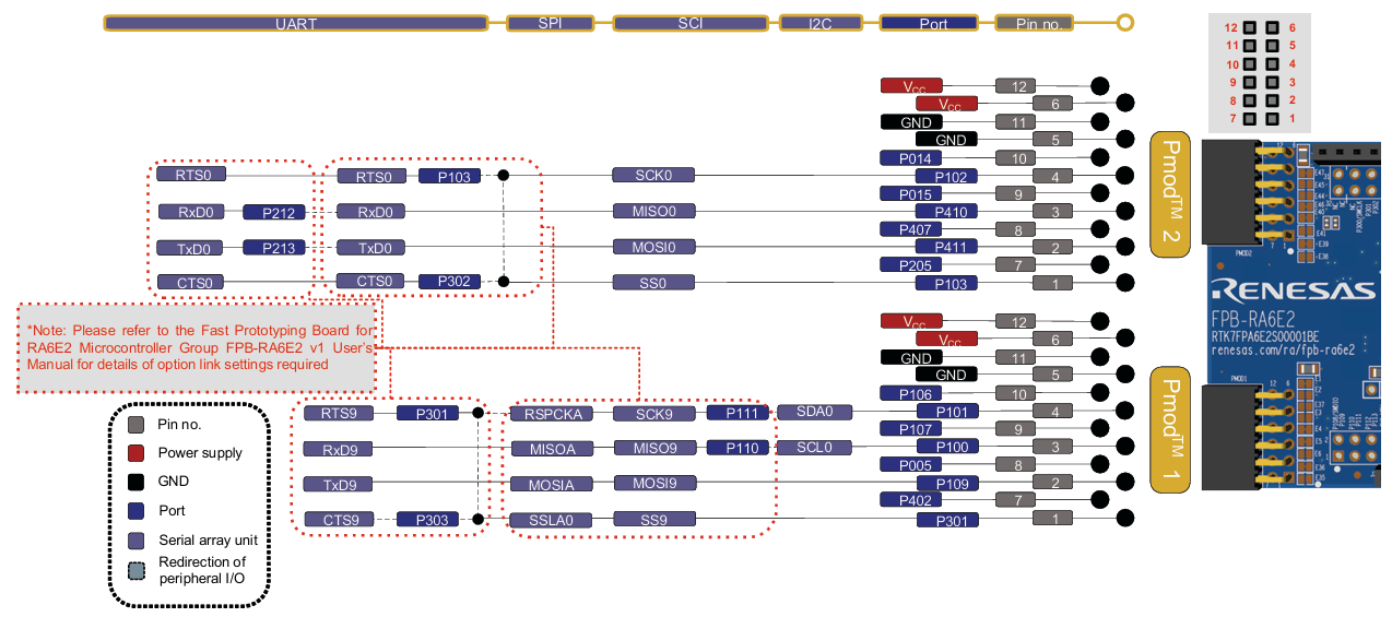
接口: 提供两路 Pmod 接口和 Arduino Uno R3 接口,扩展传感器非常方便。
调试器: 自带 E2 Lite 调试电路,通过一根 USB-C 线即可完成供电和程序烧录。
按键与LED: 板载 2 个用户按键和 2 个用户 LED,非常适合快速验证逻辑。
Figure 1. FPB-RA6E2 Board Layout
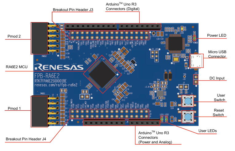
Figure 2. FPB-RA6E2 Arduino Interface
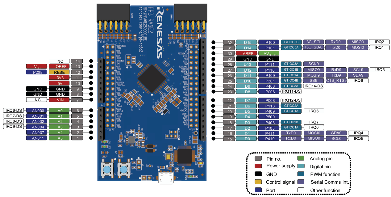
Figure 3. FPB-RA6E2 Pmod Interface
三、 开发环境搭建
瑞萨提供了完善的工具链,我选择了官方推荐的方案:
IDE: e2 studio 官方下载页面(建议下载集成了 FSP 的版本)。
FSP (Flexible Software Package): 它是瑞萨 RA 系列的灵魂,通过图形化配置大大减少了底层代码编写工作。
下载路径1:https://www.renesas.cn/zh/software-tool/e2-studio#overview
也可以直接下载带有FSP的e2 studio: https://github.com/renesas/fsp/releases到这里找到setup_fsp_v6_3_0_e2s_v2025-12.exe
或者直接点击下面的链接下载:setup_fsp_v6_3_0_e2s_v2025-12.exe
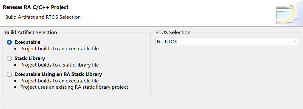
编译器: 默认使用 GCC ARM Embedded。
安装流程可以参考 【瑞萨MCU】开发环境搭建之 e2 studio
配置流程:
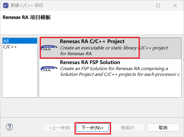
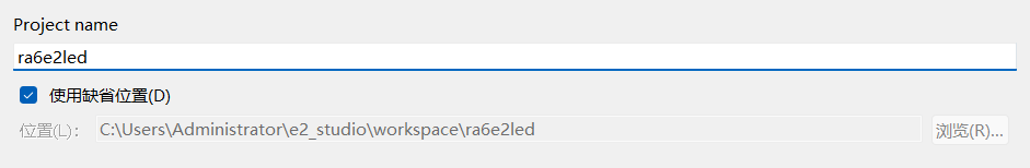
安装完毕后,打开 e2 studio,新建 RA C/C++ Project。
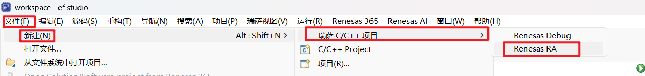
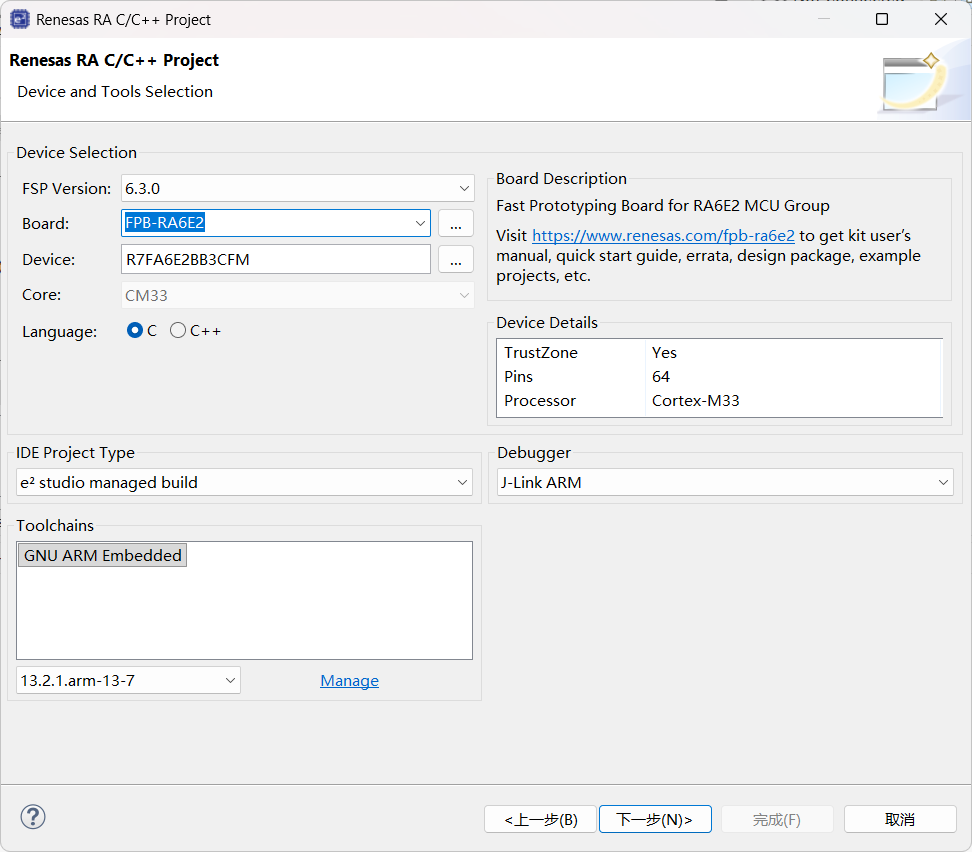
选择对应的板卡型号 FPB-RA6E2。
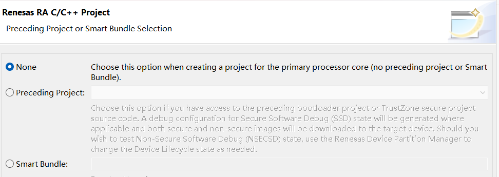
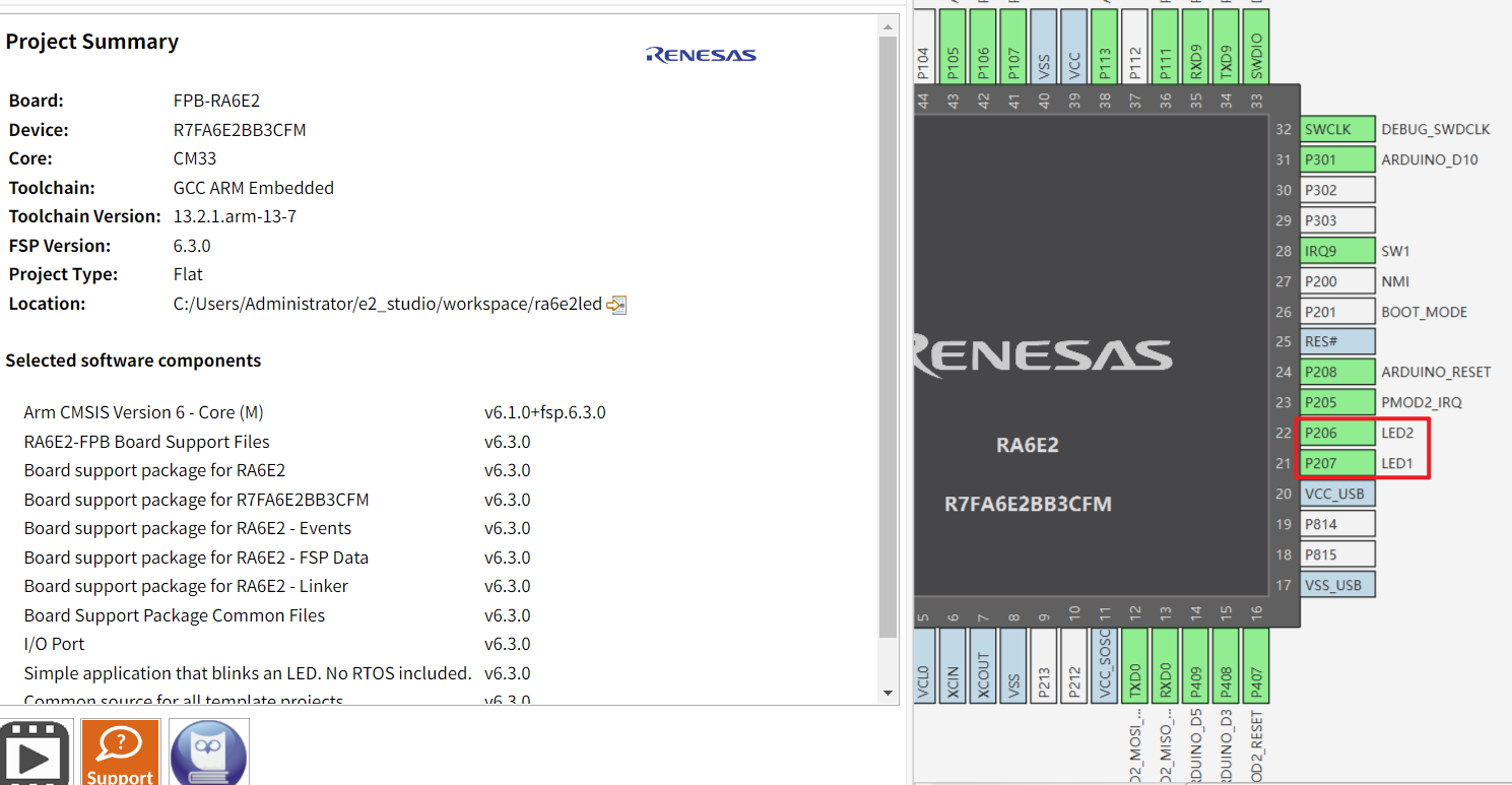
在 FSP 配置界面,可以直观地看到引脚分配和外设时钟设置。
c
/*
* Copyright (c) 2020 - 2025 Renesas Electronics Corporation and/or its affiliates
*
* SPDX-License-Identifier: BSD-3-Clause
*/

#include "hal_data.h"

extern bsp_leds_t g_bsp_leds;

/*******************************************************************************************************************//**
 * @brief  Blinky example application
 *
 * Blinks all leds at a rate of 1 second using the software delay function provided by the BSP.
 *
 **********************************************************************************************************************/
void hal_entry (void)
{
#if BSP_TZ_SECURE_BUILD

    /* Enter non-secure code */
    R_BSP_NonSecureEnter();
#endif

    /* Define the units to be used with the software delay function */
    const bsp_delay_units_t bsp_delay_units = BSP_DELAY_UNITS_MILLISECONDS;

    /* Set the blink frequency (must be <= bsp_delay_units / 2) */
    const uint32_t freq_in_hz = 1;

    /* Calculate the delay in terms of bsp_delay_units */
    const uint32_t delay = bsp_delay_units / (freq_in_hz * 2);

    /* LED type structure */
    bsp_leds_t leds = g_bsp_leds;

    /* Wake up 2nd core if this is first core and we are inside a multicore project. */
#if (0 == _RA_CORE) && (1 == BSP_MULTICORE_PROJECT) && !BSP_TZ_NONSECURE_BUILD
    R_BSP_SecondaryCoreStart();
#endif

    /* If this board has no LEDs then trap here */
    if (0 == leds.led_count)
    {
        while (1)
        {
            ;                          // There are no LEDs on this board
        }
    }

    /* Holds level to set for pins */
    bsp_io_level_t pin_level = BSP_IO_LEVEL_LOW;

    while (1)
    {
        /* Enable access to the PFS registers. If using r_ioport module then register protection is automatically
         * handled. This code uses BSP IO functions to show how it is used.
         */
        R_BSP_PinAccessEnable();

#if BSP_NUMBER_OF_CORES == 1

        /* Update all board LEDs */
        for (uint32_t i = 0; i < leds.led_count; i++)
        {
            /* Get pin to toggle */
            uint32_t pin = leds.p_leds[i];

            /* Write to this pin */
            R_BSP_PinWrite((bsp_io_port_pin_t) pin, pin_level);
        }
#else

        /* Update LED that is at the index of this core. */
        R_BSP_PinWrite((bsp_io_port_pin_t) leds.p_leds[_RA_CORE], pin_level);
#endif

        /* Protect PFS registers */
        R_BSP_PinAccessDisable();

        /* Toggle level for next write */
        if (BSP_IO_LEVEL_LOW == pin_level)
        {
            pin_level = BSP_IO_LEVEL_HIGH;
        }
        else
        {
            pin_level = BSP_IO_LEVEL_LOW;
        }

        /* Delay */
        R_BSP_SoftwareDelay(delay, bsp_delay_units);
    }
}
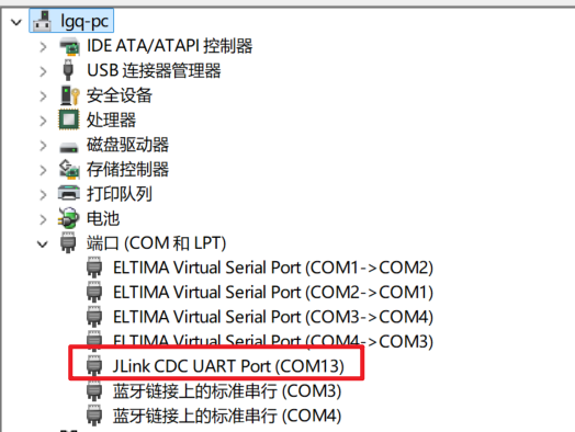
连接之前需要确保设备管理器中显示了Jlink设备
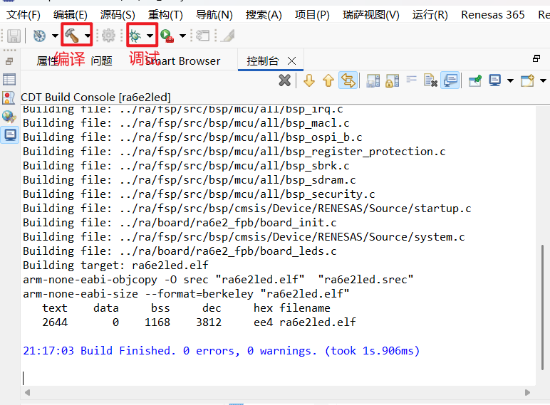
运行结果:
ra6e2_led