**前言:**本文为手把手教学的基于 STM32 的嵌入式系统 RT-Thread 移植教程,使用 STM32F103ZET6 作为核心 MCU 进行操作。本篇博客的教程为纯手动移植 RT-Thread 操作系统,且基于 STM32 的 HAL 库版本进行开发。RT-Thread 作为如今很火的嵌入式实时操作系统被广泛应由于物联网与工业设计等领域,它的设计架构也与 Linux 有异曲同工之妙,从而备受广大工程师好评。希望这篇博文能给读者朋友的工程项目给予些许帮助,Respect(代码开源)!
**硬件与软件:**STM32F103ZET6、RT-Thread、WCH COMTransmit
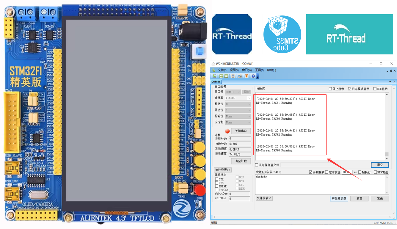
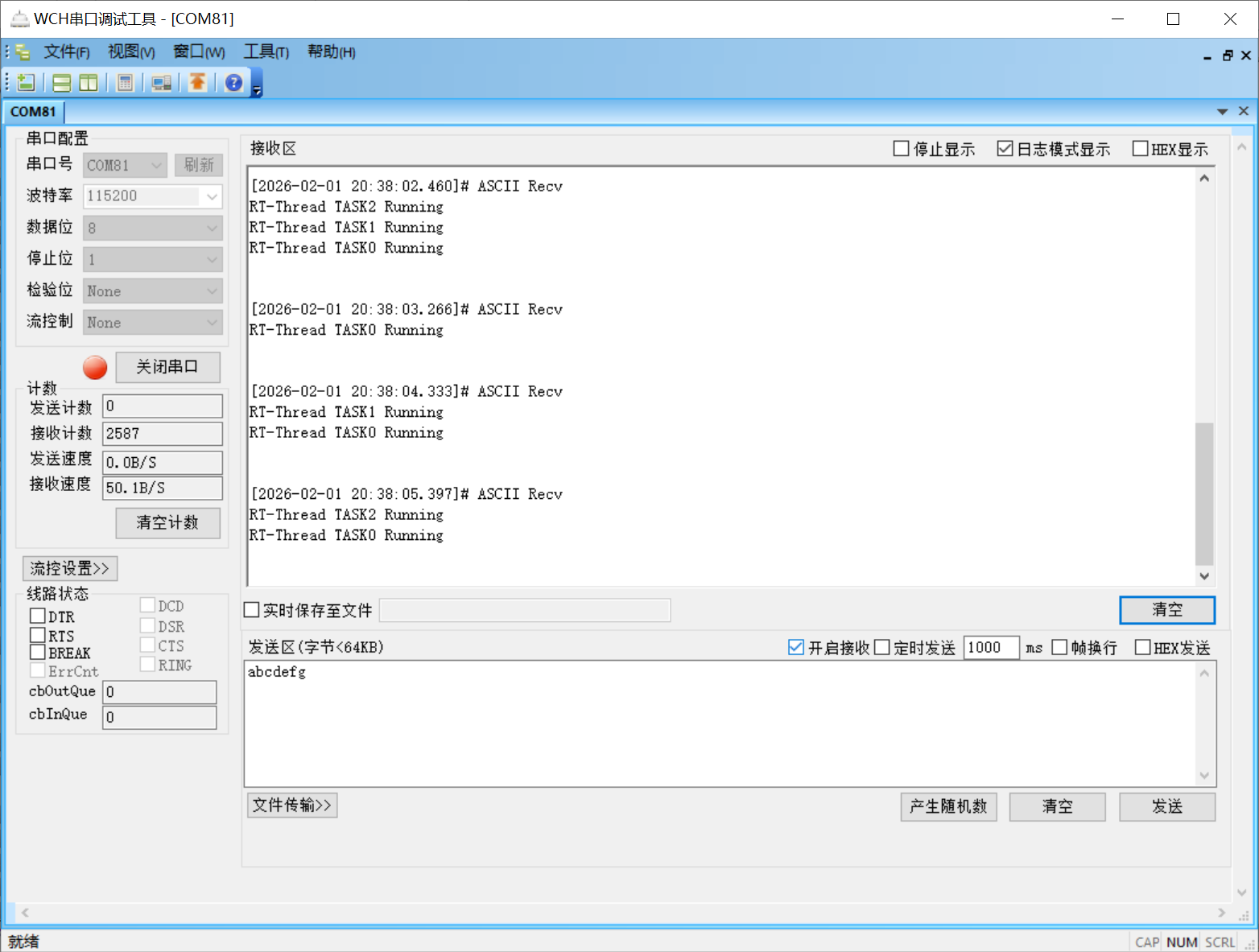
项目结果图:
RT- Thread 官网地址:rt-thread.org
RT- Thread 文档中心:https://www.rt-thread.org/document/site
一、嵌入式系统 RT-Thread 概述
1.1 RT-Thread 概述
RT-Thread(Real Time-Thread)是一款诞生于 2006 年的国产开源实时操作系统(RTOS),由熊谱翔先生创始,上海睿赛德科技负责开发维护和运营,遵循 Apache License v2.0 开源协议,可以进行免费商业化的嵌入式操作系统。RT-Thread 已从单一实时内核发展为完整的物联网操作系统平台,累计支撑全球超过 25 亿台设备运行,社区开发者规模突破 30 万。

**作者补充:**RT-Thread 拥有着极其丰富的组件、各种各样的软件包和对应各大厂商的开发板的 BSP,并且 RT-RT-Thread 还提供了自己官方的 IDE 软件 RT-Thread Studio,针对 RT-Thread 在 MCU 芯片上的部署和搭建进行了便捷化操作。RT-Thread 也是现在物联网设备很流行的 RTOS,所以如果打算入行物联网产品设计的工程师们,可以考虑学习使用这款系统!
1.2 RT-Thread 的核心框架与版本
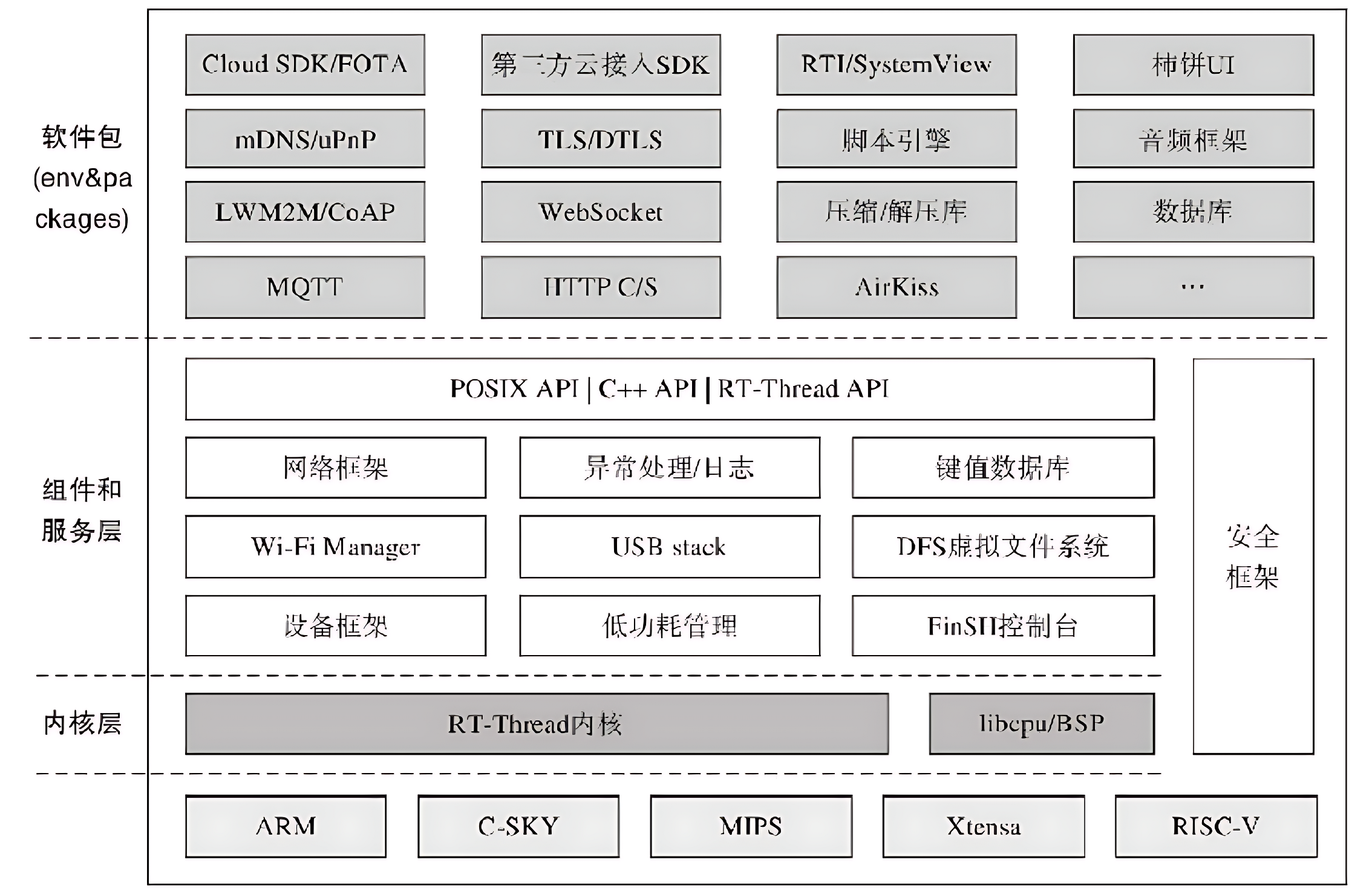
RT-Thread 的模块化设计分为:内核层、组件与服务层、软件包层。这样的设计既保证了系统的实时性与稳定性,又提升了开发灵活性。
1、The Lowest Level:Kernel layer
Kernel layer:这是 RT-Thread 的核心基础,也是整个操作系统的 "心脏",直接对接硬件内核(如 Cortex-M 内核的 CPU 寄存器、中断控制器等),提供最核心的实时系统能力。
核心组件:任务调度器、内存管理器、中断管理器、时钟管理器、同步互斥模块(信号量、互斥量、事件、消息队列)
2、The Middle Layer:Component and Service Layer
Component and Service Layer:这是衔接内核层和上层应用的桥梁层,基于内核层提供的基础能力,封装出标准化、模块化的组件和服务,向上提供统一的编程接口,屏蔽底层硬件差异。
核心组件:设备驱动框架、虚拟文件系统(DFS)、网络协议栈(LwIP)、Finsh/MSH Shell 调试组件、低功耗管理框架(PM)、图形界面(RT-GUI)。
3、The Top Layer: Software package layer
Software package layer:这是 RT-Thread 的功能扩展层,由官方和社区维护的海量第三方软件包组成,是系统生态的核心体现,开发者可按需集成,无需从零开发。
RT-Thread 版本分支:
- RT-Thread Nano:超轻量级内核(仅 2KB ROM/1KB RAM),面向资源极度受限的 8/16/32 位 MCU,无动态内存分配
- RT-Thread Standard:全功能 RTOS,面向主流 32 位 MCU(Cortex-M4/M7/RISC-V 等),支持完整组件生态
- RT-Thread Smart:面向带 MMU 的处理器(Cortex-A/RISC-V 等),支持进程隔离和动态加载,兼容 Linux 应用
1.3 各大主流嵌入式操作系统对比
主流的嵌入式实时操作系统包含有:FreeRTOS、RT-Thread、uCos、Zephyr 和 VxWorks。
1、FreeRTOS:全球最普及的轻量级开源 RTOS,MIT 协议,专注内核层,系统定位:小型嵌入式设备、消费电子、传感器节点;
2、RT-Thread:国产开源轻量级物联网 RTOS,Apache 2.0 协议,支持免费商用,系统定位:智能家居、工业控制、智能穿戴、国产芯片项目;
3、uCos:商业化实时操作系统,需授权使用,通过多项安全认证(ISO 26262、IEC 61508),系统定位:航空航天、汽车电子、医疗设备等对安全性要求严苛的领域;
4、Zephyr:Linux 基金会旗下开源 RTOS,面向物联网和边缘计算,系统定位:智能硬件、工业物联网、车规级设备;
5、VxWorks:高端商用实时操作系统,业界实时性标杆,系统定位:航空航天、国防军工、轨道交通、工业控制高端设备;
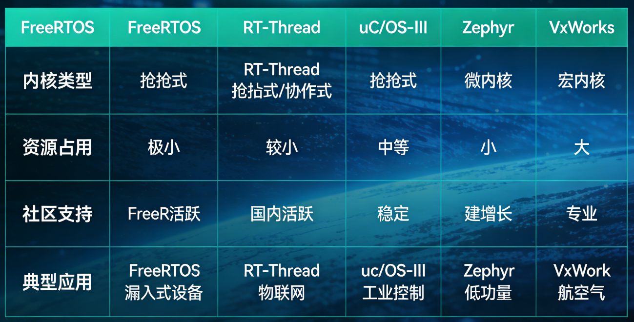
各大主流 RTOS 都有各自的特点与优势,工程师应该根据设计的产品特性、研发周期和综合成本作为衡量,选择适合项目的那套架构。RT-Thread 的架构设计与编程框架还是很舒服的,其中间层兼容了很多物联网的协议包,故特别适合物联网产品的开发。
二、RT-Thread 源码下载与介绍
2.1 RT-Thread 源码下载
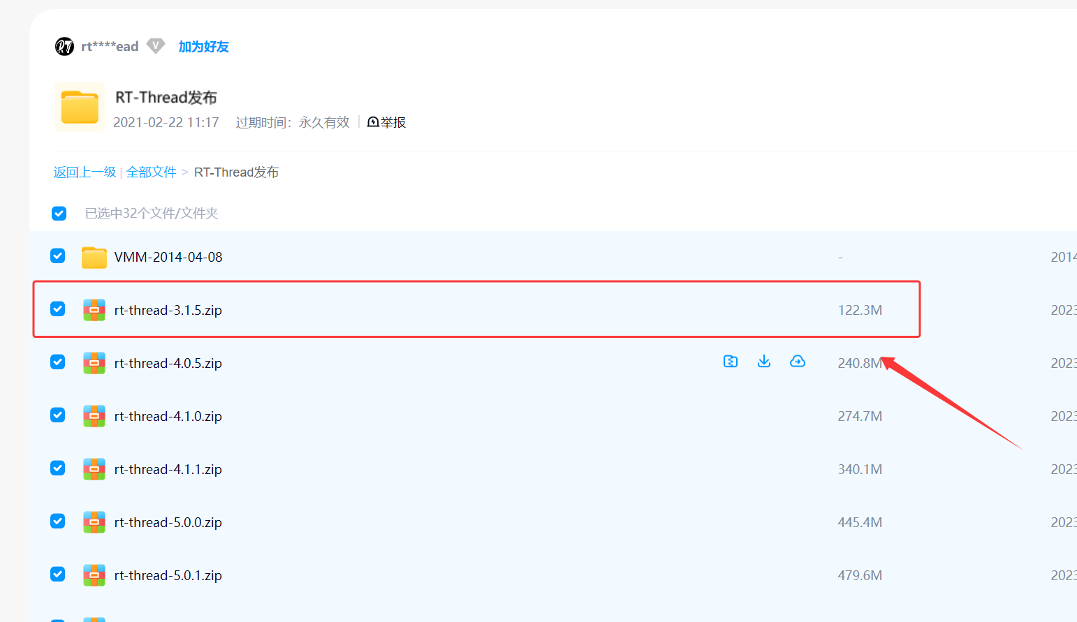
1、我们首先拿到 RT-Thread nano 源码:rt-thread.org/download.html
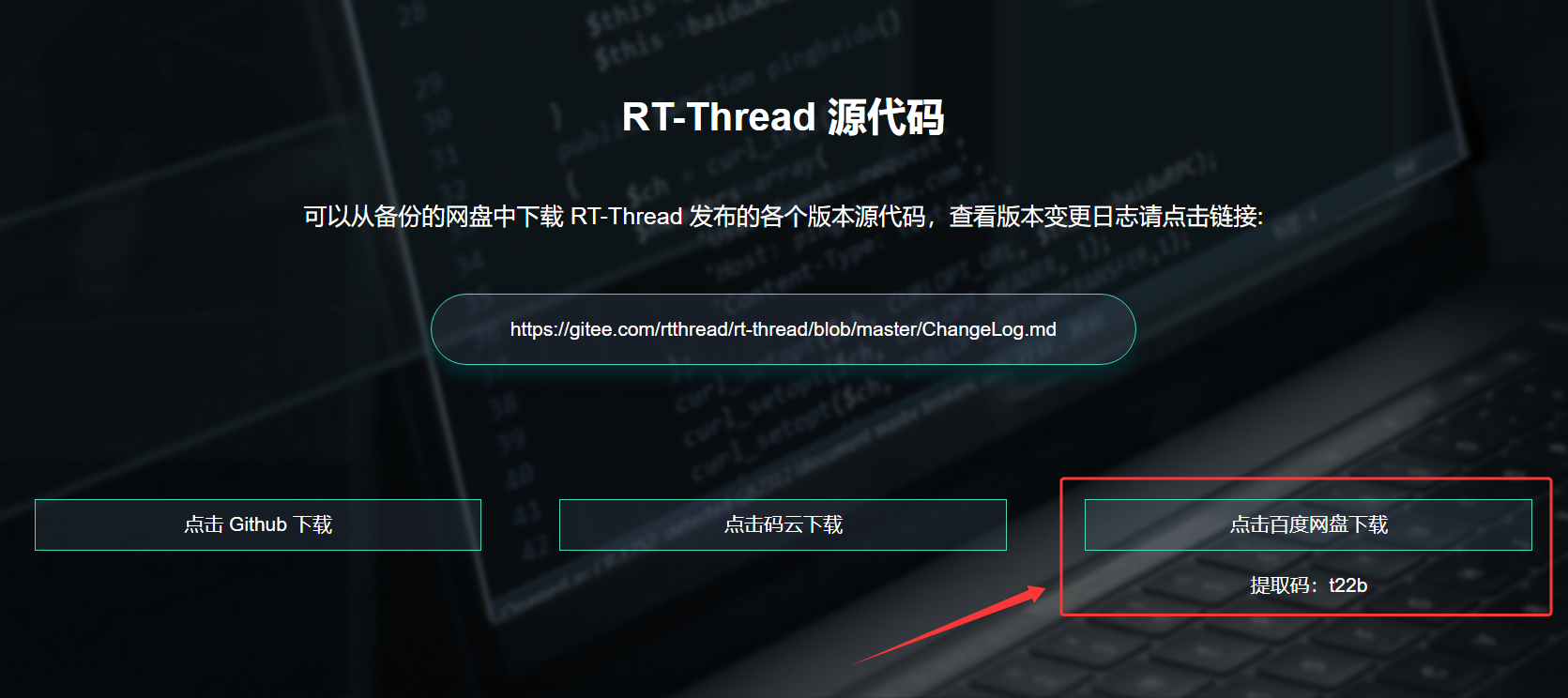
2、作者在百度网盘中这边选择 RT-Thread-3.1.5 的版本文件,大家可以根据自己的需求选择最新的版本;
RT-Thread 3.x 系列整体架构一致,均为「微内核 + 组件化」,小版本迭代以 BUG 修复、性能优化、轻量功能新增为主,无架构性变更,3.1.5 是 3.x 系列的黄金稳定版(里程碑),与同系列版本的差异集中在「稳定性、细节优化、兼容性」
2.2 RT-Thread 源码介绍
RT-Thread 的源码采用内核与组件解耦、硬件与软件分层的目录设计,整体遵循嵌入式 RTOS 标准化规范,所有文件 / 目录按「核心内核→硬件适配→功能组件→板级驱动→应用示例→开发工具」分层组织,可按需裁剪,核心组成以一级目录为核心单元,配套根目录关键配置文件,作者这边仅介绍一下源码中核心和关键的文件。
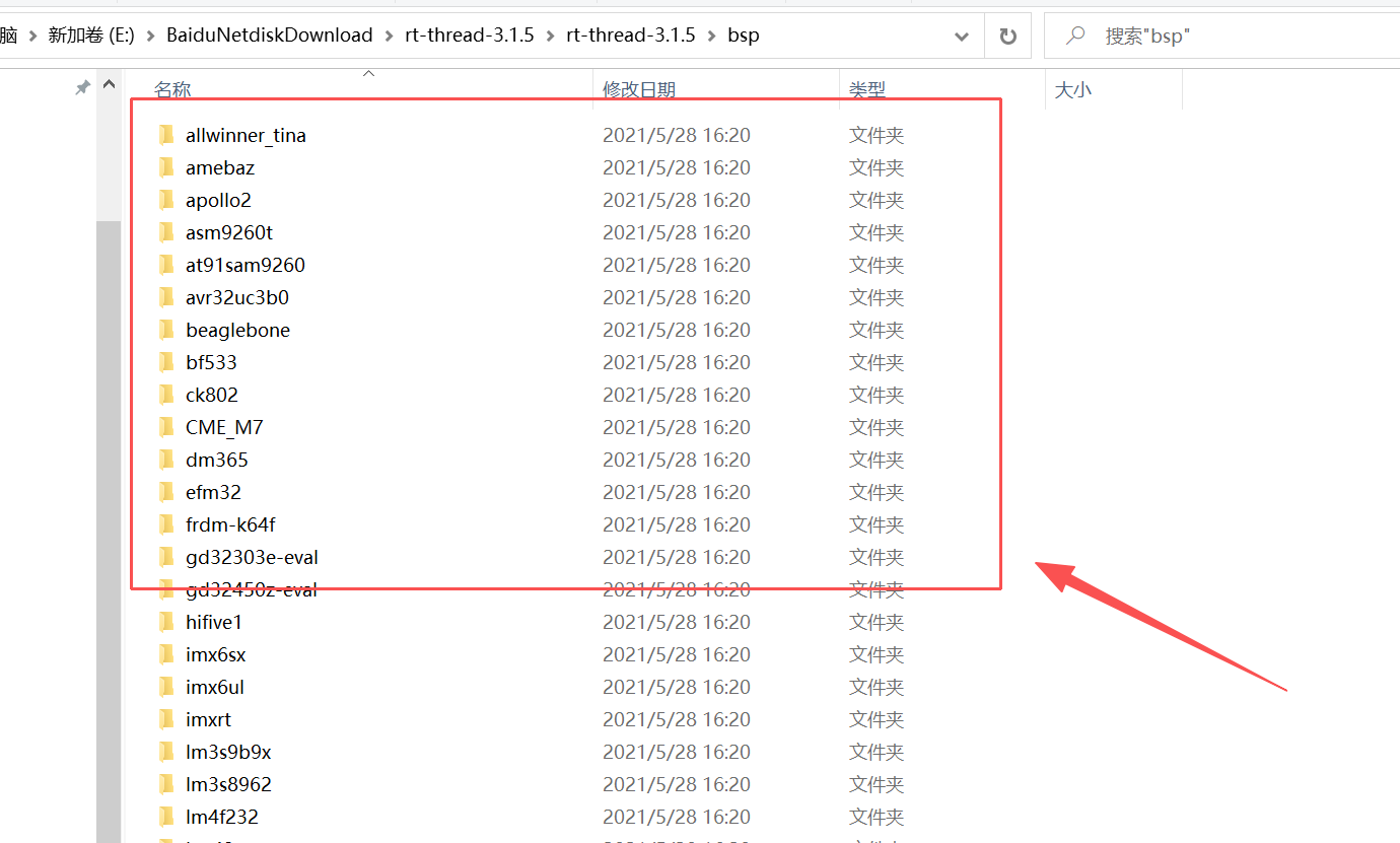
1、rt-thread-3.1.5/bsp:
RT-Thread 3.1.5 中的 bsp/ 是Board Support Package(板级支持包) 目录的缩写,也是 RT-Thread 实现「上层系统与底层硬件解耦」的核心目录,专为具体 MCU 型号 / 开发板提供一站式专属硬件适配代码集合,是 RT-Thread 移植到实际硬件的关键载体。bsp 也是我们移植 RT-Thread 系统的核心操作点。
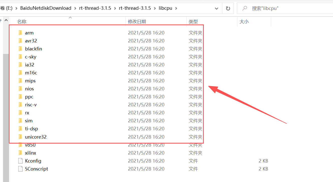
2、rt-thread-3.1.5/libcpu
存放不同 CPU 内核的底层适配代码,解耦上层内核与底层硬件,让内核无需修改即可运行在不同 MCU 上,核心特点是「按 CPU 架构分目录」(而非按 MCU 型号),比如:1、arm/:主流 ARM 架构适配(3.1.5 主打 Cortex-M3/M4,如 STM32F1/F4),包含上下文切换汇编代码、中断向量表、系统时钟初始化、关 / 开中断封装等硬件相关底层代码;2、其他架构:如 risc-v/、mips/(3.1.5 对非主流架构适配较少);
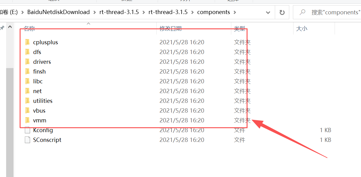
3、rt-thread-3.1.5/components
存放 RT-Thread 3.1.5 的标准化可裁剪组件,是区别于 2.x 系列的核心(2.x 无标准化组件体系),所有组件基于内核实现,独立编译、可按需开启 / 关闭,开发中直接调用组件 API 即可,核心组件包含:1、finsh/: RT-Thread 专属的命令行调试组件(Shell),支持串口命令交互、查看系统状态、调用自定义函数,3.1.5 新增命令补全 / 历史记录功能;**2、drivers/:**通用设备驱动框架,定义 SPI /I2C /UART /ADC 等外设的标准化驱动接口,解耦上层应用与底层硬件驱动;
RT-Thread 的源码目录中还包含了很多有用的文件夹,包括:documentation、tools、src、include、example 等,作者这边就不一样介绍了,感兴趣的读者朋友们可以在 RT-Thread 官网手册中去了解和学习。
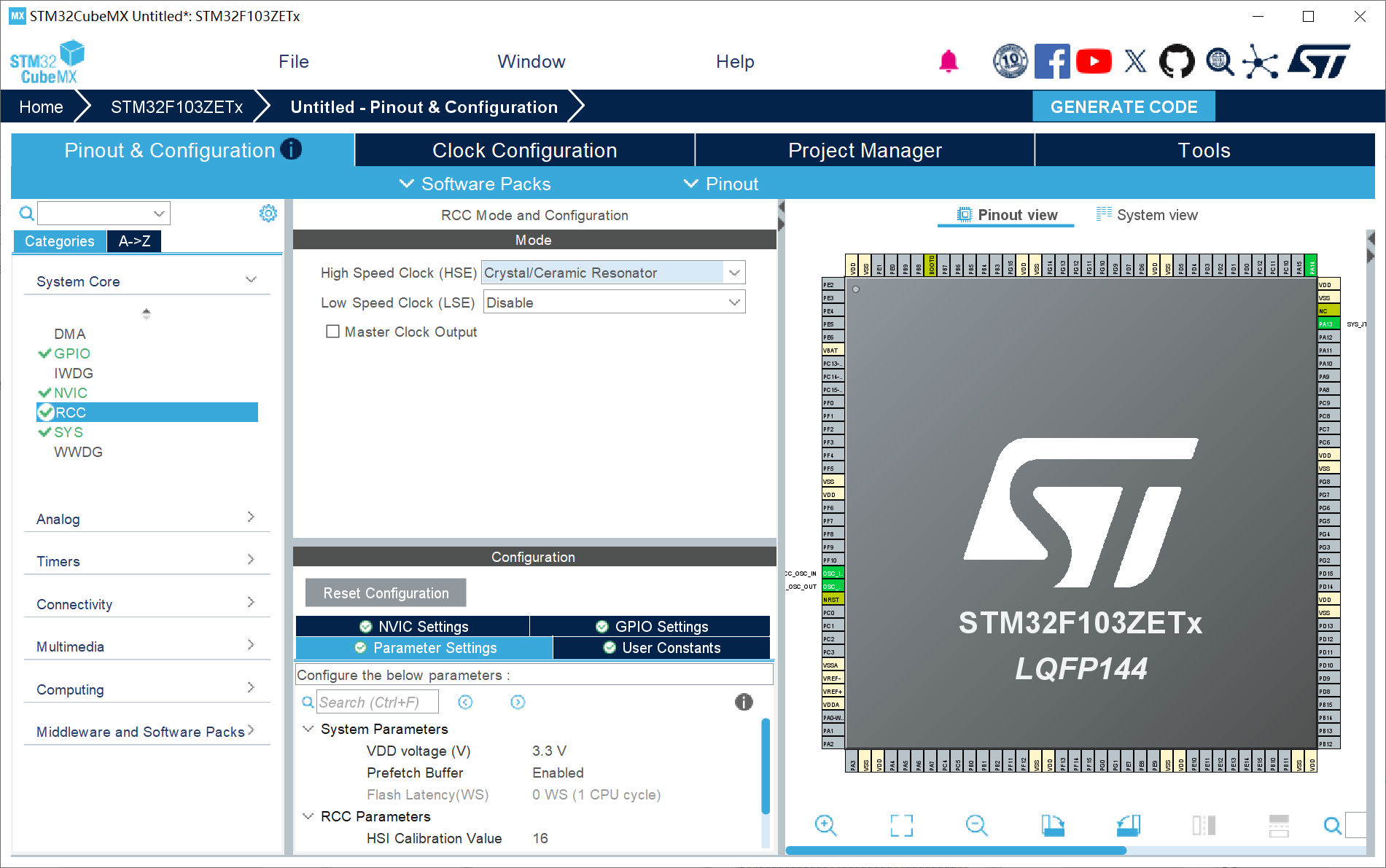
三、STM32CubeMX 配置
1、RCC配置外部高速晶振(精度更高)------HSE;
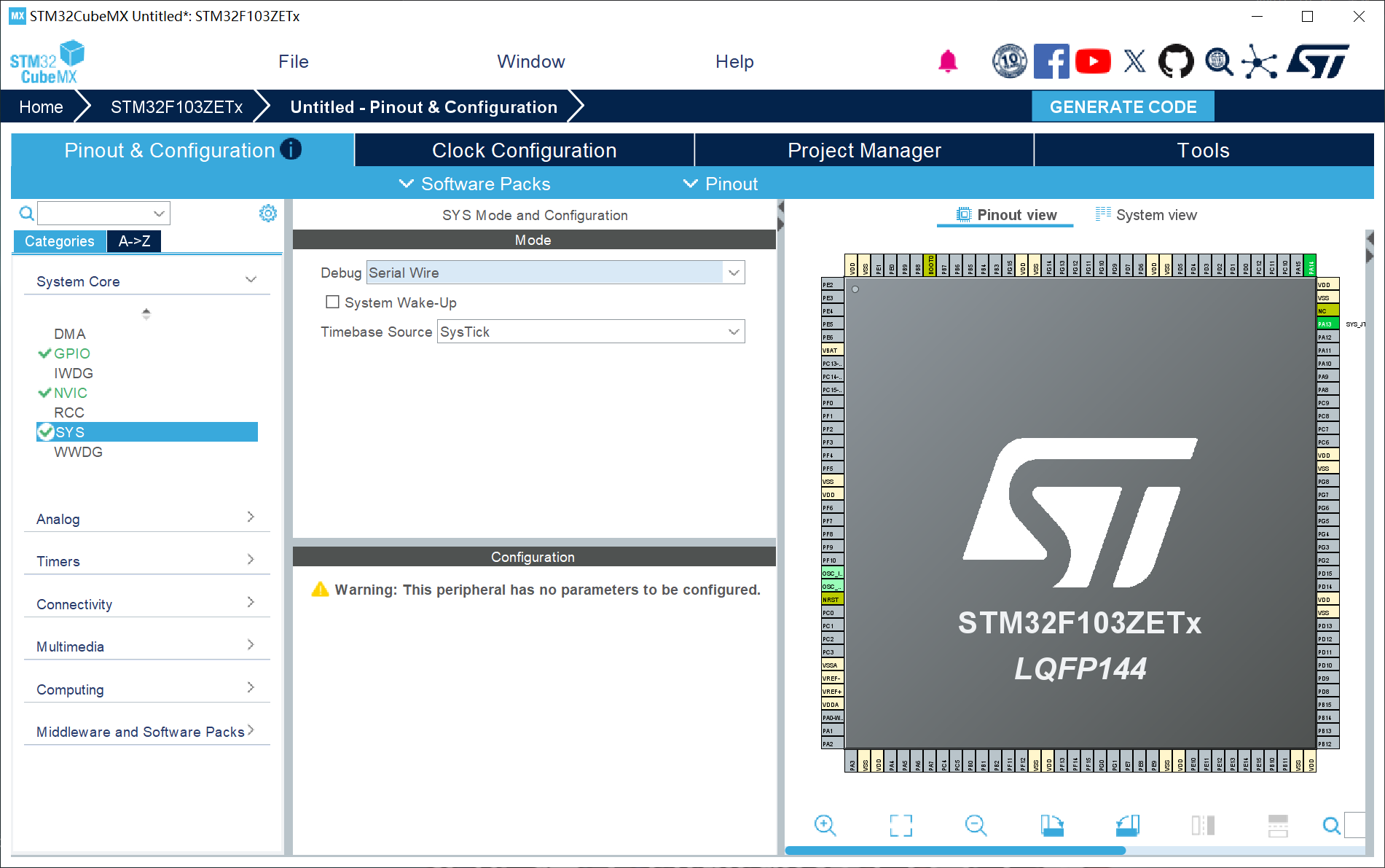
2、SYS配置:Debug设置成Serial Wire (否则可能导致芯片自锁);
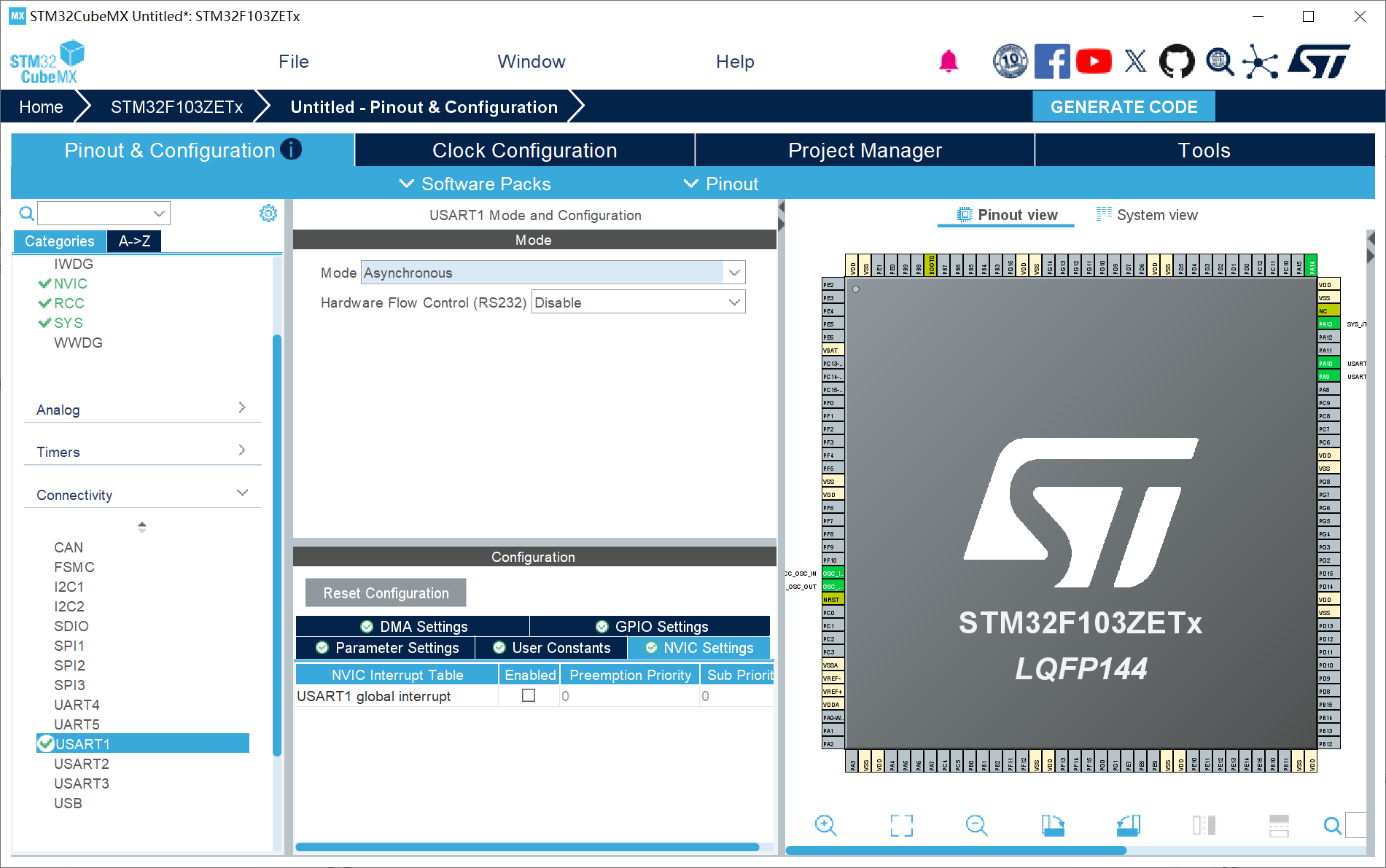
3、UART1配置:使用串口打印作为 RT-Thread 的多任务机制操作;
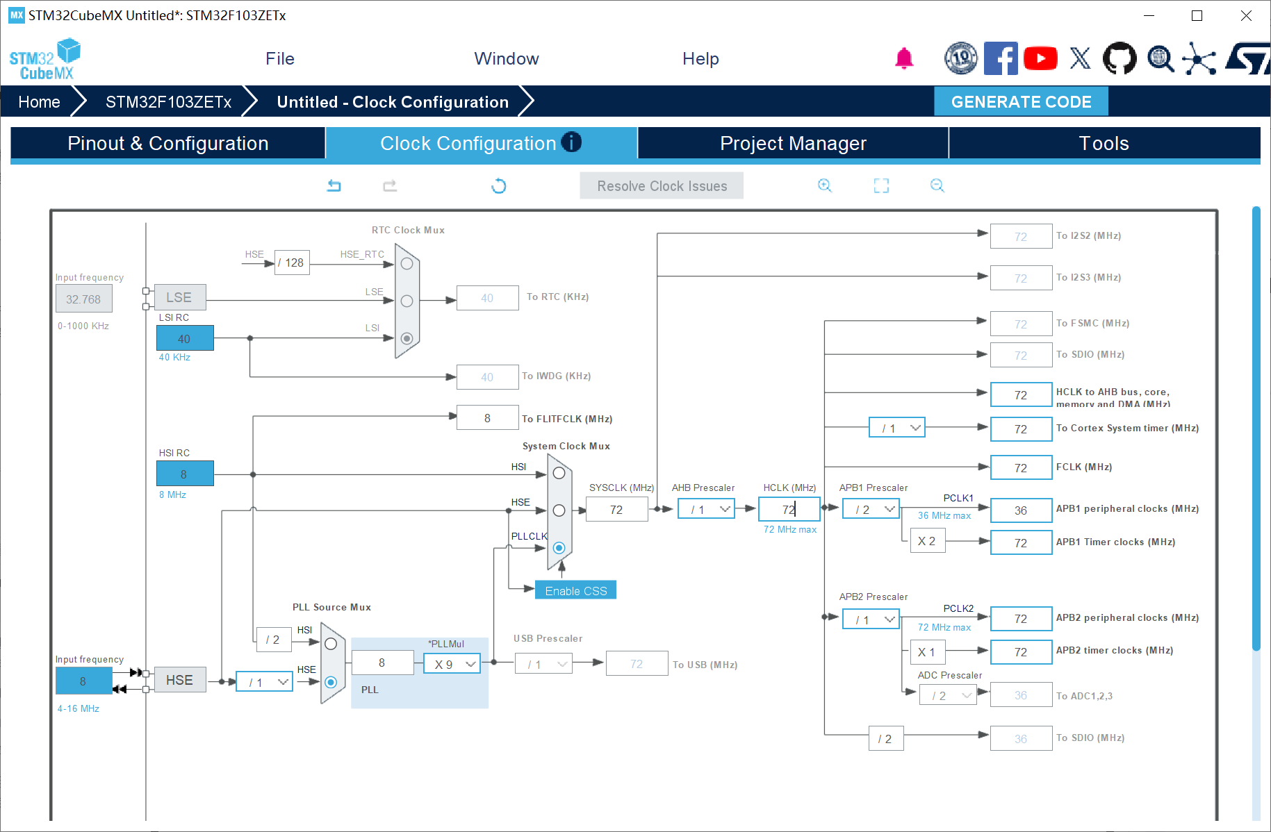
4、时钟树配置
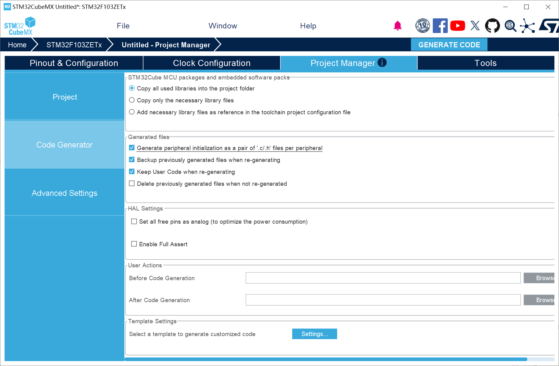
5、工程配置
四、RT-Thread 代码移植与编写
4.1 RT-Thread 代码移植
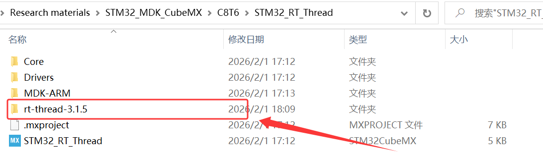
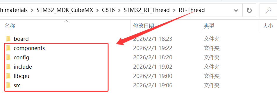
1、将解压的 rt-thread-3.1.5 源码复制到工程文件夹目录下,并创建一个 RT-Thread 文件夹;
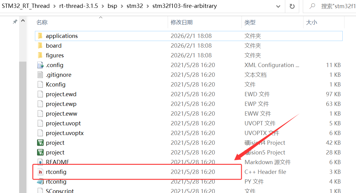
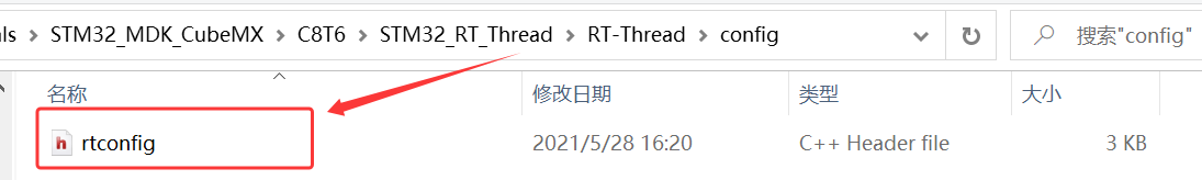
2、将 \STM32_RT_Thread\rt-thread-3.1.5\bsp\stm32\stm32f103-fire-arbitrary 下的 rtconfig.h 复制到 RT_Thread 下的文件夹 config;
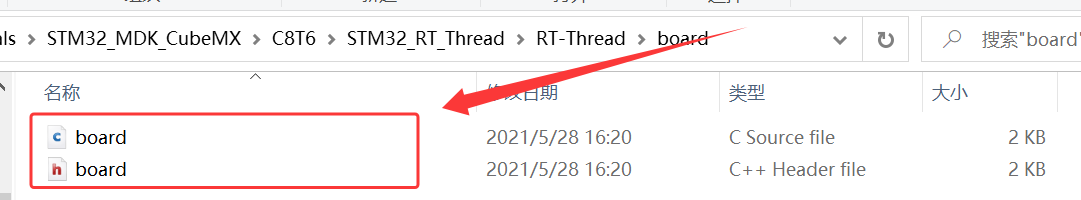
3、将 \STM32_RT_Thread\rt-thread-3.1.5\bsp\stm32\stm32f103-fire-arbitrary\board 下的 board.c、board.h 复制到 RT_Thread 下的文件夹 board;
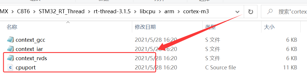
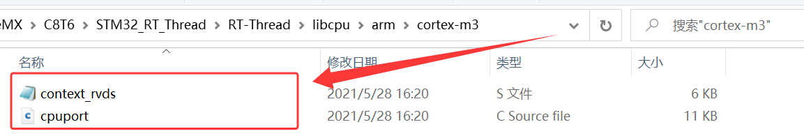
4、根据自己的实际硬件平台具有的内核架构选择,将 \STM32_RT_Thread\rt-thread-3.1.5\libcpu\arm\cortex-m3 下的 context_rvds.S、cpuport.c 复制到 \STM32_RT_Thread\RT_Thread\libcpu\arm\cortex-m3;
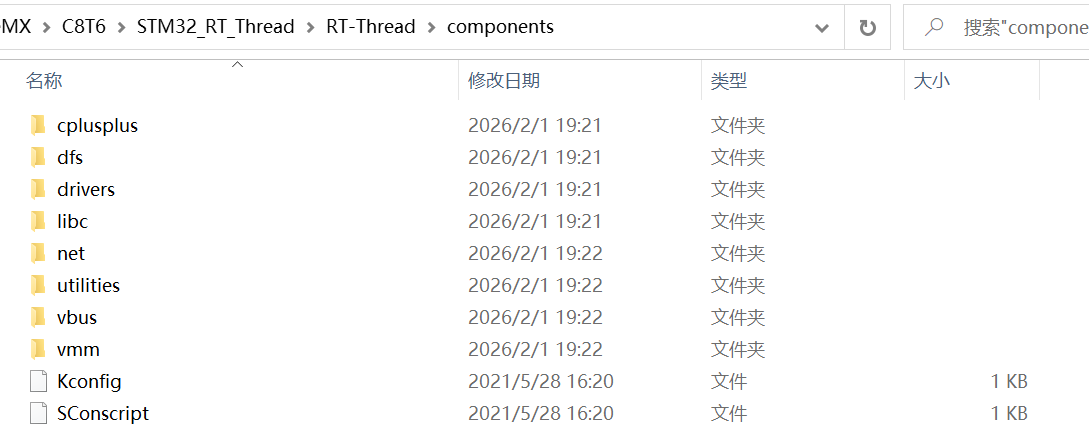
5、将 \STM32_RT_Thread\rt-thread-3.1.5 下的 include、src 和 components 文件夹整个复制到 \STM32_RT_Thread\RT_Thread 下,并且把 components下的 finsh 组件删除;
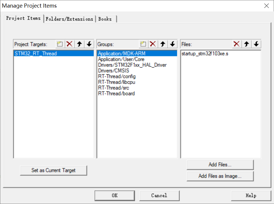
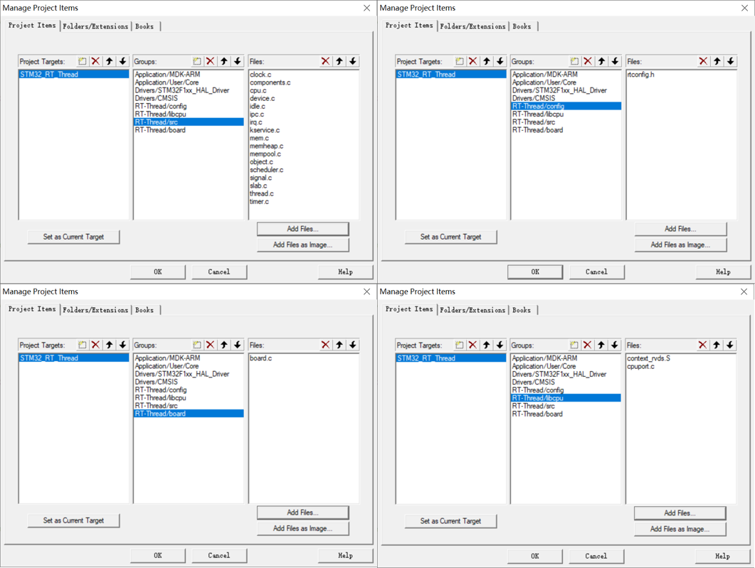
6、在 KEIL 里新建 4 个组别 RT_Thread/config,RT_Thread/libcpu,RT_Thread/src,RT_Thread/board,并在 4 个组内添加对应程序文件;
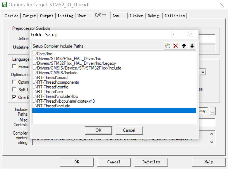
7、在 KEIL 中添加对应路径;
4.2 RT-Thread 任务代码编写
1、重写 printf 函数:
cpp
#include "stdio.h"
//重定义
int fputc(int c,FILE *stream)
{
uint8_t ch[1]={c};
HAL_UART_Transmit(&huart1,ch,1,0xFFFF);
return c;
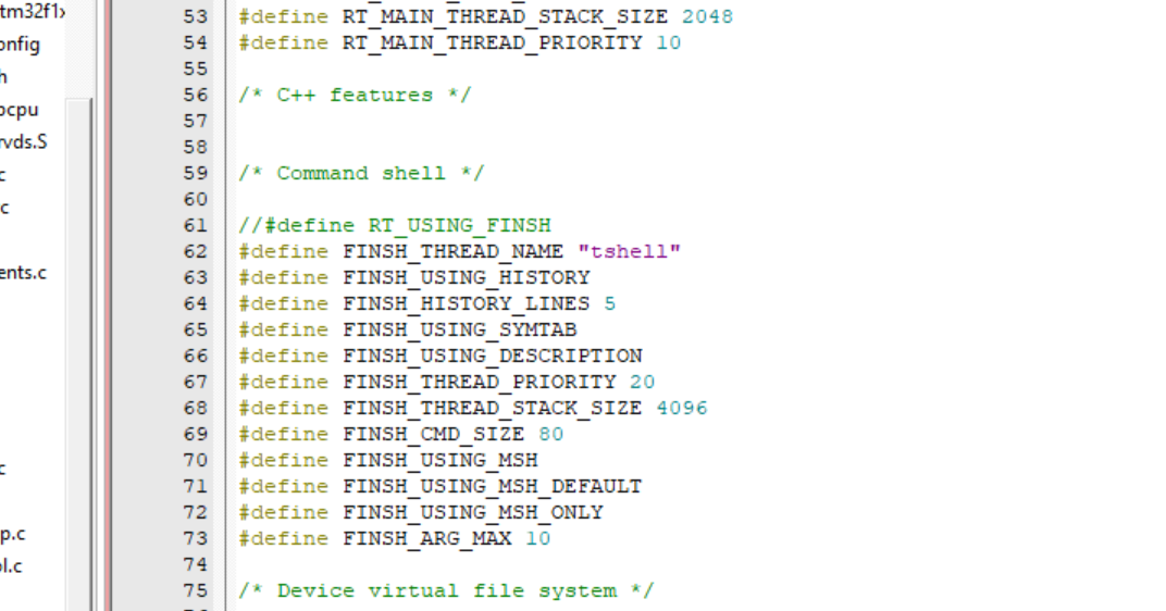
}2、注释掉 #define RT_USING_FINSH,因为暂时不会用到 finsh 组件;
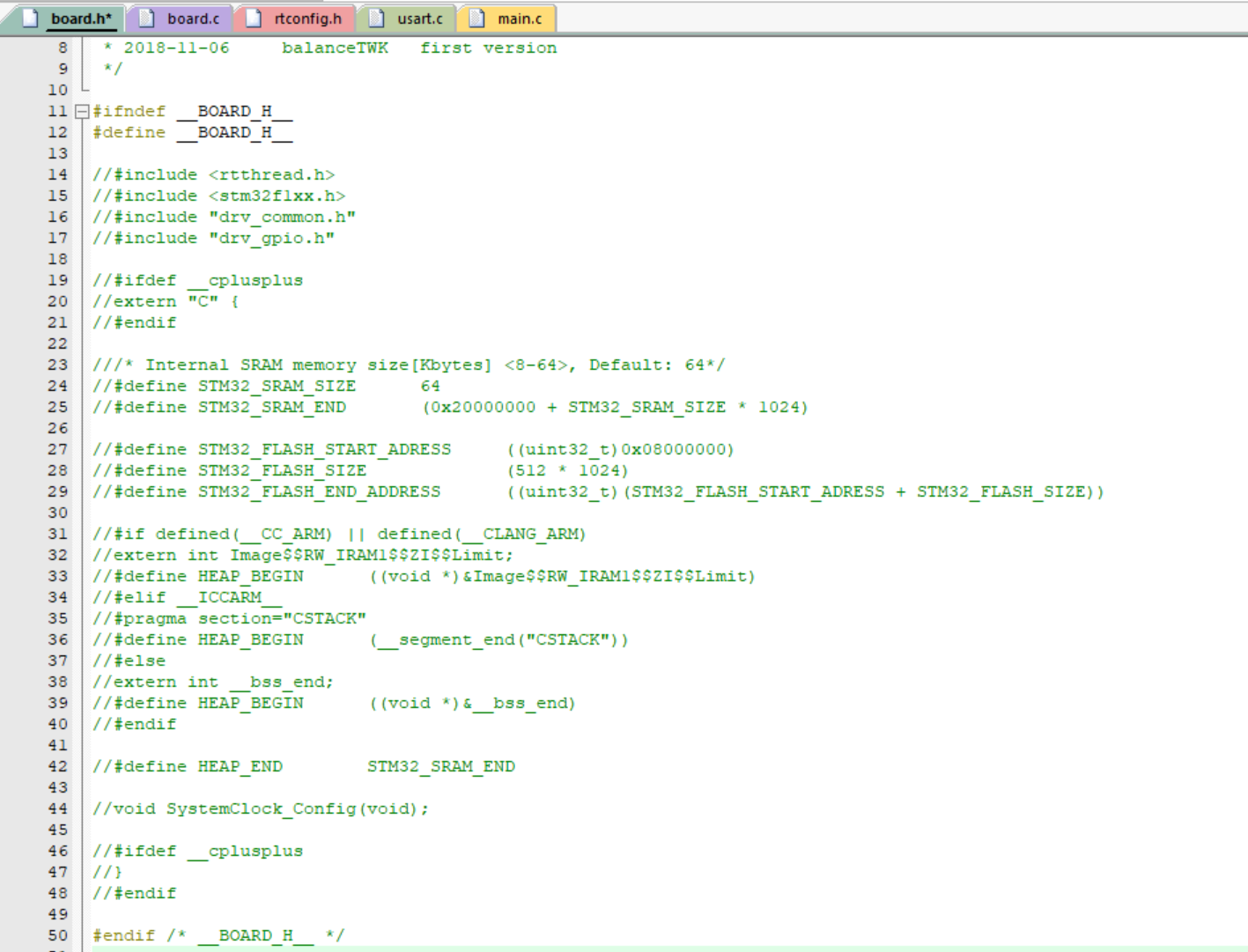
3、注释掉 board.h 的内容;
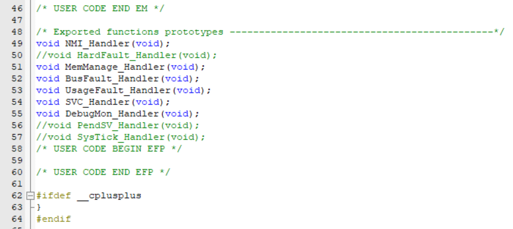
4、存在有重定义,故在 stm32f1xx_it.h 则注释掉 PendSV_Handler,SysTick_Handler, HardFault_Handler;
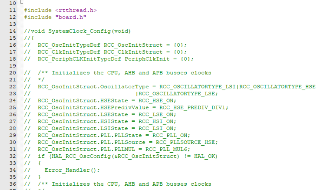
5、本来 RT-Thread 已经定义了 void SystemClock_Config(void),这里注释掉 board.c 的 SystemClock_Config,后面将使用 STM32CubeMX 生成的 SystemClock_Config;
6、重新编写 board.c,board. h;
board.h:
cpp
#ifndef __BOARD_H__
#define __BOARD_H__


#include "stm32f1xx_hal.h"

void rt_hw_board_init(void);
void SysTick_Handler(void);

#endif /* __BOARD_H__ */
board.c:
cpp
/*
 * Copyright (c) 2006-2021, RT-Thread Development Team
 *
 * SPDX-License-Identifier: Apache-2.0
 *
 * Change Logs:
 * Date           Author       Notes
 * 2018-11-06     balanceTWK   first version
 */

#include <rtthread.h>
#include "board.h"

#include "board.h"

#include <rthw.h>
#include <rtthread.h>

#include "main.h"
#include "usart.h"
#include "gpio.h"

#include "stdio.h"

#if defined(RT_USING_USER_MAIN) && defined(RT_USING_HEAP)
/*
 * Please modify RT_HEAP_SIZE if you enable RT_USING_HEAP
 * the RT_HEAP_SIZE max value = (sram size - ZI size), 1024 means 1024 bytes
 */
#define RT_HEAP_SIZE (15*1024)
static rt_uint8_t rt_heap[RT_HEAP_SIZE];

RT_WEAK void *rt_heap_begin_get(void)
{
    return rt_heap;
}

RT_WEAK void *rt_heap_end_get(void)
{
    return rt_heap + RT_HEAP_SIZE;
}
#endif

void rt_os_tick_callback(void)
{
    rt_interrupt_enter();

    rt_tick_increase();

    rt_interrupt_leave();
}

/**
 * This function will initial your board.
 */
void rt_hw_board_init(void)
{
	/* 初始化 SysTick */
	extern void SystemClock_Config(void);
	SystemClock_Config();

	//下面放硬件初始化
	MX_GPIO_Init();
	MX_USART1_UART_Init();

#ifdef RT_USING_COMPONENTS_INIT
    rt_components_board_init();
#endif

#if defined(RT_USING_USER_MAIN) && defined(RT_USING_HEAP)
    rt_system_heap_init(rt_heap_begin_get(), rt_heap_end_get());
#endif

}

#ifdef RT_USING_CONSOLE

static int uart_init(void)
{
//#error "TODO 2: Enable the hardware uart and config baudrate."
    return 0;
}
INIT_BOARD_EXPORT(uart_init);

void rt_hw_console_output(const char *str)
{
//#error "TODO 3: Output the string 'str' through the uart."
}

#endif


void SysTick_Handler(void)
{
    /* 进入中断 */
    rt_interrupt_enter();

    /* 更新时基 */
    rt_tick_increase();

    /* 离开中断 */
    rt_interrupt_leave();
}
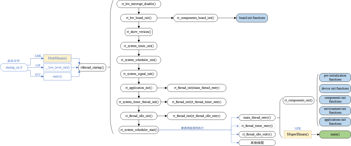
在 board.c 中将进行初始化,RT-Thread 系统的启动流程如下:
7、编写 main.c 文件:
main.c:
cpp
/* USER CODE BEGIN Header */
/**
******************************************************************************
* @file : main.c
* @brief : Main program body
******************************************************************************
* @attention
*
* Copyright (c) 2026 STMicroelectronics.
* All rights reserved.
*
* This software is licensed under terms that can be found in the LICENSE file
* in the root directory of this software component.
* If no LICENSE file comes with this software, it is provided AS-IS.
*
******************************************************************************
*/
/* USER CODE END Header */
/* Includes ------------------------------------------------------------------*/
#include "main.h"
#include "usart.h"
#include "gpio.h"
/* Private includes ----------------------------------------------------------*/
/* USER CODE BEGIN Includes */
#include "stdio.h"
#include "board.h"
#include "rtthread.h"
/* USER CODE END Includes */
/* Private typedef -----------------------------------------------------------*/
/* USER CODE BEGIN PTD */
/* USER CODE END PTD */
/* Private define ------------------------------------------------------------*/
/* USER CODE BEGIN PD */
/* USER CODE END PD */
/* Private macro -------------------------------------------------------------*/
/* USER CODE BEGIN PM */
/* USER CODE END PM */
/* Private variables ---------------------------------------------------------*/
/* USER CODE BEGIN PV */
/*定义线程控制块*/
static struct rt_thread task0_thread;
/* 定义线程控栈时要求 RT_ALIGN_SIZE 个字节对齐 */
ALIGN(RT_ALIGN_SIZE)
/* 定义线程栈 */
static rt_uint8_t rt_task0_thread_stack[1024];
/*定义线程控制块*/
static struct rt_thread task1_thread;
/* 定义线程控栈时要求 RT_ALIGN_SIZE 个字节对齐 */
ALIGN(RT_ALIGN_SIZE)
/* 定义线程栈 */
static rt_uint8_t rt_task1_thread_stack[1024];
/*定义线程控制块*/
static struct rt_thread task2_thread;
/* 定义线程控栈时要求 RT_ALIGN_SIZE 个字节对齐 */
ALIGN(RT_ALIGN_SIZE)
/* 定义线程栈 */
static rt_uint8_t rt_task2_thread_stack[1024];
/* USER CODE END PV */
/* Private function prototypes -----------------------------------------------*/
void SystemClock_Config(void);
/* USER CODE BEGIN PFP */
//声明线程函数
static void task0_thread_entry(void* parameter);
static void task1_thread_entry(void* parameter);
static void task2_thread_entry(void* parameter);
/* USER CODE END PFP */
/* Private user code ---------------------------------------------------------*/
/* USER CODE BEGIN 0 */
/* USER CODE END 0 */
/**
* @brief The application entry point.
* @retval int
*/
int main(void)
{
/* USER CODE BEGIN 1 */
/*
* 开发板硬件初始化,RTT 系统初始化已经在 main 函数之前完成,
* 即在 component.c 文件中的 rtthread_startup()函数中完成了。
* 所以在 main 函数中,只需要创建线程和启动线程即可。
*/
/* USER CODE END 1 */
/* MCU Configuration--------------------------------------------------------*/
/* Reset of all peripherals, Initializes the Flash interface and the Systick. */
// HAL_Init();
/* USER CODE BEGIN Init */
/* USER CODE END Init */
/* Configure the system clock */
// SystemClock_Config();
/* USER CODE BEGIN SysInit */
/* USER CODE END SysInit */
/* Initialize all configured peripherals */
// MX_GPIO_Init();
// MX_USART1_UART_Init();
/* USER CODE BEGIN 2 */
printf("**************** STM32 RT-Thread TEST ****************\r\n");
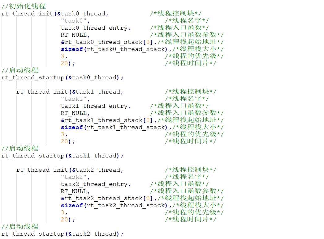
//初始化线程
rt_thread_init(&task0_thread, /*线程控制块*/
"task0", /*线程名字*/
task0_thread_entry, /*线程入口函数*/
RT_NULL, /*线程入口函数参数*/
&rt_task0_thread_stack[0],/*线程栈起始地址*/
sizeof(rt_task0_thread_stack),/*线程栈大小*/
3, /*线程的优先级*/
20); /*线程时间片*/
//启动线程
rt_thread_startup(&task0_thread);
rt_thread_init(&task1_thread, /*线程控制块*/
"task1", /*线程名字*/
task1_thread_entry, /*线程入口函数*/
RT_NULL, /*线程入口函数参数*/
&rt_task1_thread_stack[0],/*线程栈起始地址*/
sizeof(rt_task1_thread_stack),/*线程栈大小*/
3, /*线程的优先级*/
20); /*线程时间片*/
//启动线程
rt_thread_startup(&task1_thread);
rt_thread_init(&task2_thread, /*线程控制块*/
"task2", /*线程名字*/
task2_thread_entry, /*线程入口函数*/
RT_NULL, /*线程入口函数参数*/
&rt_task2_thread_stack[0],/*线程栈起始地址*/
sizeof(rt_task2_thread_stack),/*线程栈大小*/
3, /*线程的优先级*/
20); /*线程时间片*/
//启动线程
rt_thread_startup(&task2_thread);
/* USER CODE END 2 */
/* Infinite loop */
/* USER CODE BEGIN WHILE */
while (1)
{
/* USER CODE END WHILE */
/* USER CODE BEGIN 3 */
}
/* USER CODE END 3 */
}
/**
* @brief System Clock Configuration
* @retval None
*/
void SystemClock_Config(void)
{
RCC_OscInitTypeDef RCC_OscInitStruct = {0};
RCC_ClkInitTypeDef RCC_ClkInitStruct = {0};
/** Initializes the RCC Oscillators according to the specified parameters
* in the RCC_OscInitTypeDef structure.
*/
RCC_OscInitStruct.OscillatorType = RCC_OSCILLATORTYPE_HSE;
RCC_OscInitStruct.HSEState = RCC_HSE_ON;
RCC_OscInitStruct.HSEPredivValue = RCC_HSE_PREDIV_DIV1;
RCC_OscInitStruct.HSIState = RCC_HSI_ON;
RCC_OscInitStruct.PLL.PLLState = RCC_PLL_ON;
RCC_OscInitStruct.PLL.PLLSource = RCC_PLLSOURCE_HSE;
RCC_OscInitStruct.PLL.PLLMUL = RCC_PLL_MUL9;
if (HAL_RCC_OscConfig(&RCC_OscInitStruct) != HAL_OK)
{
Error_Handler();
}
/** Initializes the CPU, AHB and APB buses clocks
*/
RCC_ClkInitStruct.ClockType = RCC_CLOCKTYPE_HCLK|RCC_CLOCKTYPE_SYSCLK
|RCC_CLOCKTYPE_PCLK1|RCC_CLOCKTYPE_PCLK2;
RCC_ClkInitStruct.SYSCLKSource = RCC_SYSCLKSOURCE_PLLCLK;
RCC_ClkInitStruct.AHBCLKDivider = RCC_SYSCLK_DIV1;
RCC_ClkInitStruct.APB1CLKDivider = RCC_HCLK_DIV2;
RCC_ClkInitStruct.APB2CLKDivider = RCC_HCLK_DIV1;
if (HAL_RCC_ClockConfig(&RCC_ClkInitStruct, FLASH_LATENCY_2) != HAL_OK)
{
Error_Handler();
}
}
/* USER CODE BEGIN 4 */
//定义线程函数
static void task0_thread_entry(void* parameter)
{
while(1)
{
printf("RT-Thread TASK0 Running\r\n");
rt_thread_delay(1000); /* 延时 1000 个 tick */
}
}
//定义线程函数
static void task1_thread_entry(void* parameter)
{
while(1)
{
printf("RT-Thread TASK1 Running\r\n");
rt_thread_delay(2000); /* 延时 2000 个 tick */
}
}
//定义线程函数
static void task2_thread_entry(void* parameter)
{
while(1)
{
printf("RT-Thread TASK2 Running\r\n");
rt_thread_delay(3000); /* 延时 3000 个 tick */
}
}
/* USER CODE END 4 */
/**
* @brief This function is executed in case of error occurrence.
* @retval None
*/
void Error_Handler(void)
{
/* USER CODE BEGIN Error_Handler_Debug */
/* User can add his own implementation to report the HAL error return state */
__disable_irq();
while (1)
{
}
/* USER CODE END Error_Handler_Debug */
}
#ifdef USE_FULL_ASSERT
/**
* @brief Reports the name of the source file and the source line number
* where the assert_param error has occurred.
* @param file: pointer to the source file name
* @param line: assert_param error line source number
* @retval None
*/
void assert_failed(uint8_t *file, uint32_t line)
{
/* USER CODE BEGIN 6 */
/* User can add his own implementation to report the file name and line number,
ex: printf("Wrong parameters value: file %s on line %d\r\n", file, line) */
/* USER CODE END 6 */
}
#endif /* USE_FULL_ASSERT */RT-Thread 操作系统的多任务创建与其他主流 RTOS 的创建方式都很一致,故工程师在编写代码的时候上手都会很快,读者朋友们可以根据作者上述创建的 3 个 TASK 任务进行自由发挥最大化利用 RT-Thread 操作系统。
4.3 RT-Thread 运行情况
五、代码开源
代码地址: 基于STM32的嵌入式操作系统RT-Thread项目代码资源-CSDN下载
如果积分不够的朋友,点波关注,评论区留下邮箱,作者无偿提供源码和后续问题解答。求求啦关注一波吧 !!!