【 声明:版权所有,欢迎转载,请勿用于商业用途。 联系信箱:feixiaoxing @163.com】
和can比起来,虽然can也是差分模块,在汽车领域用的很多,但是相对而言,大家还是喜欢用485总线外界设备。不仅和ttl类似,而且有一定的抗干扰性,而且可以外挂很多的设备,应用范围很广。但是很多设备是不带ttl转485芯片的,比如esp32模块大多数就没有485接口。所以这个时候,可以买一个ttl转换模块,就能解决这个485接口问题。
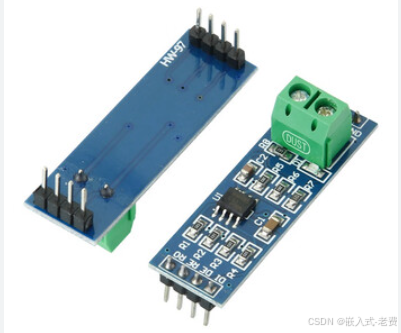
1、ttl转485模块的作用
主要就是tx/rx变成差分信号。
2、模块接口信号
ttl转485模块的信号,输入这边就是3.3v/tx/rx/gnd。tx/rx/gnd这三个pin要连接,一般都是知道的。但是很多人会忘记连接3.3v,这会导致后面收到的报文是乱码。发送这边就是A/B/GND。
3、485连接
485连接这边就是,A-A,B-B,GND-GND,不像TTL需要交叉连接。模块上面有个拨码开关,一般保持关闭即可。另外就是,模块的tx/rx不需要和ttl交叉连接,直连就好。
4、103c8t6测试代码
为了验证ttl转485的收发能力,可以找一块带485的103开发板。在这块开发板上面,做一个自收自发的功能即可。
#include "stm32f10x.h"

#define RS485_TX_EN()    GPIO_SetBits(GPIOA, GPIO_Pin_4)
#define RS485_RX_EN()     GPIO_ResetBits(GPIOA, GPIO_Pin_4)
#define RX_BUF_SIZE   128

volatile uint8_t  rxBuf[RX_BUF_SIZE];
volatile uint16_t rxLen = 0;
volatile uint8_t  rxFrameReady = 0;   // 1 means a complete frame has been received and is ready to process

void LED_Init(void)
{
	RCC_APB2PeriphClockCmd(RCC_APB2Periph_GPIOB, ENABLE);

	GPIO_InitTypeDef GPIO_InitStructure;  // set port attribute
	GPIO_InitStructure.GPIO_Mode = GPIO_Mode_Out_PP;
	GPIO_InitStructure.GPIO_Pin = GPIO_Pin_12;
	GPIO_InitStructure.GPIO_Speed = GPIO_Speed_50MHz;
	GPIO_Init(GPIOB, &GPIO_InitStructure);
}

void USART2_Init(void)
{
	GPIO_InitTypeDef GPIO_InitStructure;
	USART_InitTypeDef USART_InitStructure;
	NVIC_InitTypeDef NVIC_InitStructure;
	RCC_APB2PeriphClockCmd(RCC_APB2Periph_GPIOA, ENABLE);
	RCC_APB1PeriphClockCmd(RCC_APB1Periph_USART2, ENABLE);

	// PA2 - TX
	GPIO_InitStructure.GPIO_Mode = GPIO_Mode_AF_PP;
	GPIO_InitStructure.GPIO_Pin = GPIO_Pin_2;
	GPIO_InitStructure.GPIO_Speed = GPIO_Speed_50MHz;
	GPIO_Init(GPIOA, &GPIO_InitStructure);

	// PA3 - RX
	GPIO_InitStructure.GPIO_Mode = GPIO_Mode_IPU;
	GPIO_InitStructure.GPIO_Pin = GPIO_Pin_3;
	GPIO_Init(GPIOA, &GPIO_InitStructure);

	// PA4 - DE/RE
	GPIO_InitStructure.GPIO_Mode = GPIO_Mode_Out_PP;
	GPIO_InitStructure.GPIO_Pin = GPIO_Pin_4;
	GPIO_InitStructure.GPIO_Speed = GPIO_Speed_50MHz;
	GPIO_Init(GPIOA, &GPIO_InitStructure);
	RS485_RX_EN();

    USART_InitStructure.USART_BaudRate = 115200;
	USART_InitStructure.USART_WordLength = USART_WordLength_8b;
	USART_InitStructure.USART_StopBits = USART_StopBits_1;
	USART_InitStructure.USART_Parity = USART_Parity_No;
	USART_InitStructure.USART_HardwareFlowControl = USART_HardwareFlowControl_None;
	USART_InitStructure.USART_Mode = USART_Mode_Tx | USART_Mode_Rx;
	USART_Init(USART2, &USART_InitStructure);

    // Enable RX interrupt and IDLE line interrupt
	USART_ITConfig(USART2, USART_IT_RXNE, ENABLE);
	USART_ITConfig(USART2, USART_IT_IDLE, ENABLE);
	NVIC_InitStructure.NVIC_IRQChannel = USART2_IRQn;
	NVIC_InitStructure.NVIC_IRQChannelPreemptionPriority = 0;
	NVIC_InitStructure.NVIC_IRQChannelSubPriority = 0;
	NVIC_InitStructure.NVIC_IRQChannelCmd = ENABLE;
	NVIC_Init(&NVIC_InitStructure);
	USART_Cmd(USART2, ENABLE);
}

// Send a complete frame in one go

void USART2_SendFrame(uint8_t *buf, uint16_t len)
{
	RS485_TX_EN();

	for (uint16_t i = 0; i < len; i++)
	{
		USART_SendData(USART2, buf[i]);
		while (USART_GetFlagStatus(USART2, USART_FLAG_TXE) == RESET);
	}
	while (USART_GetFlagStatus(USART2, USART_FLAG_TC) == RESET);

	RS485_RX_EN();
}

void USART2_IRQHandler(void)
{
	if (USART_GetITStatus(USART2, USART_IT_RXNE) != RESET)
	{
		uint8_t byte = USART_ReceiveData(USART2);
		if (rxLen < RX_BUF_SIZE)
		{
			rxBuf[rxLen++] = byte;
		}
		// Reading DR automatically clears the RXNE flag
	}

	if (USART_GetITStatus(USART2, USART_IT_IDLE) != RESET)
	{
		// Clear IDLE flag: must read SR then DR, in this fixed order
		volatile uint32_t tmp;
		tmp = USART2->SR;
		tmp = USART2->DR;
		(void)tmp;
		if (rxLen > 0)
		{
			rxFrameReady = 1;   // Mark that a full frame has been received, ready for the main loop to handle
		}
	}
}

int main(void)
{
	int flag = 0;

	LED_Init();
	USART2_Init();

	while (1)
	{
		if (rxFrameReady)
		{
			// Disable RX interrupt first to prevent data being overwritten during processing
			USART_ITConfig(USART2, USART_IT_RXNE, DISABLE);
			uint16_t len = rxLen;
			USART2_SendFrame((uint8_t *)rxBuf, len);  // Send the whole frame at once
			rxLen = 0;
			rxFrameReady = 0;
			USART_ITConfig(USART2, USART_IT_RXNE, ENABLE);

			if(flag) GPIO_SetBits(GPIOB, GPIO_Pin_12); // add by feixiaoxing
			else GPIO_ResetBits(GPIOB, GPIO_Pin_12);
			flag = 1 - flag;
		}
	}
}
5、测试方法
测试方法,就是用xcom,或者是sscom周期性通过pc上的usb转ttl模块,发送报文。一方面看103开发板有没有闪烁,一方面看接收到的报文对不对。