大家好,随着国产芯片的崛起,本文将专注于使用国产fpga芯片----高云fpga实现串行fir滤波器的项目
1.fir滤波器简介
设计一个频域滤波器(将想要保留的频率段赋值为1,其他频率段赋值为0),将其与含噪声信号的频谱在频域上相乘,再将乘积做傅里叶逆变换,即可实现滤波,这种滤波器就叫频域滤波器。这个过程就是FIR滤波,FIR滤波器是有限冲激响应的滤波器,
2.FIR滤波器表达式
上述公式即为表达成有限冲激响应。
3.使用matlab生成滤波器系数
Matlab
clc;
clear;
close all;
warning off;

h = hamming(7);

figure;
plot(h,'b-o')

h2 = round(1023*h)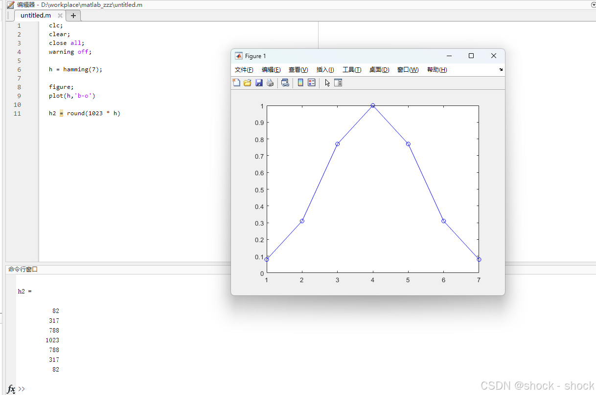
在matlab中输入上述代码,可以生成FIR汉明窗的7个系数:
h2 =
82
317
788
1023
788
317
82
4.在高云ide中实现代码编写以及仿真波形查看
为了确保本教程是适用于刚刚接触高云的所有阶段的工程师,所以将从创建工程的步骤开始讲解。
4.1 创建工程
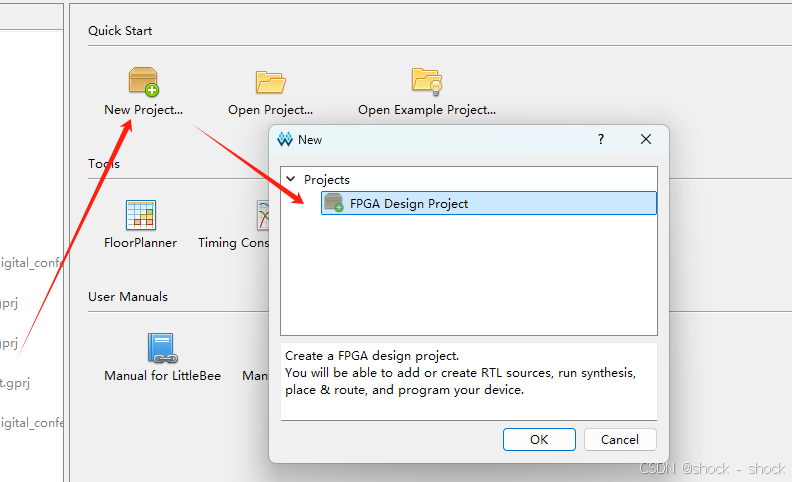
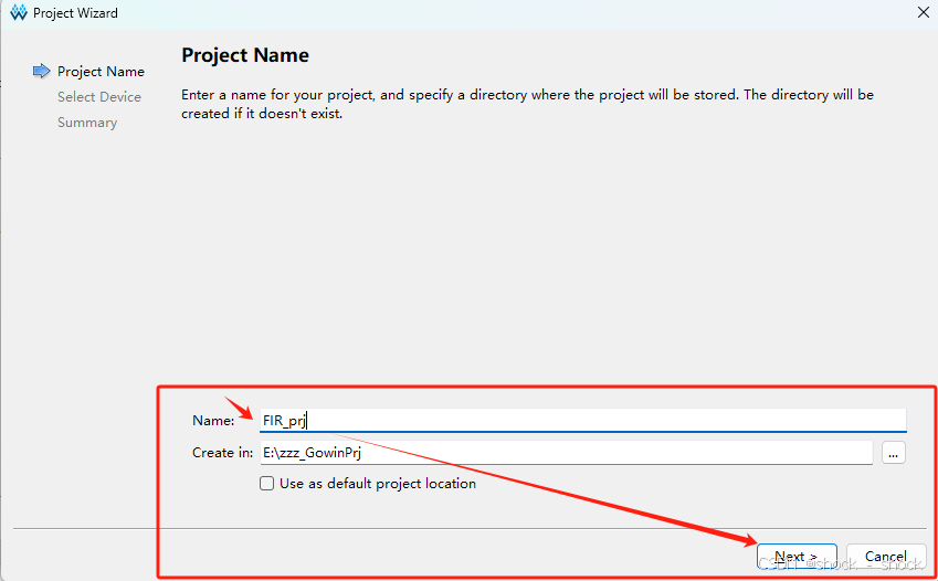
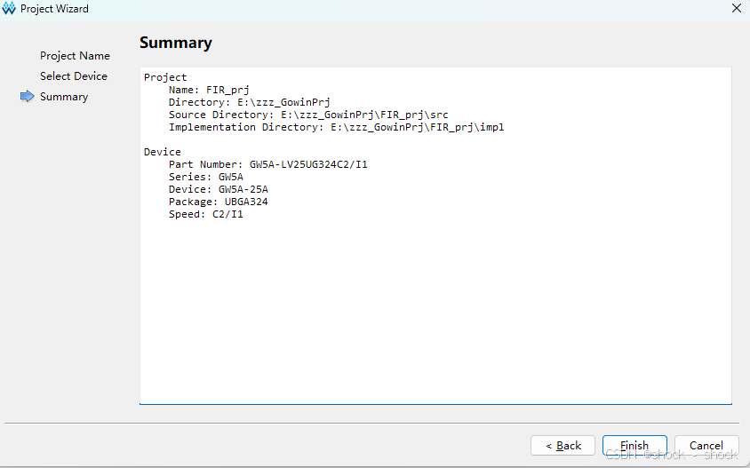
给本工程命名后点击next
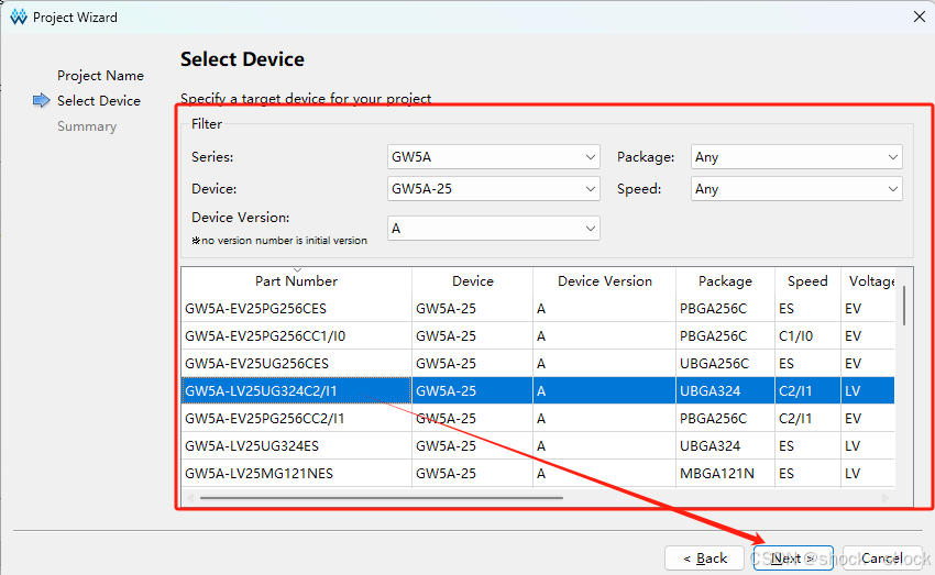
选择器件型号,由于本项目只是进行仿真,故大家可以跟着我使用相同的器件型号,也可根据自己的实际芯片来选择,确定后点击next
点击finish
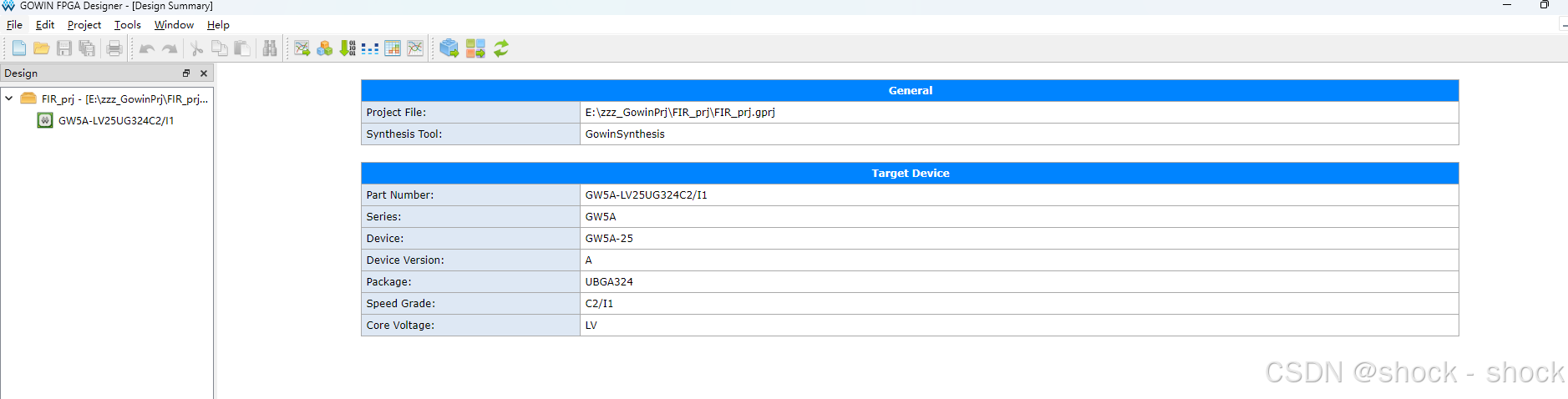
进入到下图这个界面就代表已经创建工程完成。
4.2 代码编写
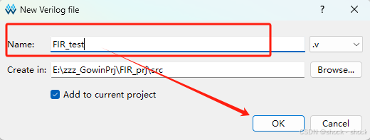
根据下图步骤来创建代码编写模块

给模块命名后点击OK即可进入代码编写阶段。
下述代码即为fir滤波器的代码实现,将代码copy进代码模块后,通过ctrl+s进行代码的保存:
Matlab
`timescale 1ns / 1ps

module FIR_test(
input i_clk,
input i_rst,
input signed[1:0]i_din,
output signed[15:0]o_dout
    );
//滤波器系数
parameter b0 =  14'd82;
parameter b1 =  14'd317;
parameter b2 =  14'd788;
parameter b3 =  14'd1023;
parameter b4 =  14'd788;
parameter b5 =  14'd317;
parameter b6 =  14'd82;

reg signed[1:0]x0;
reg signed[1:0]x1;
reg signed[1:0]x2;
reg signed[1:0]x3;
reg signed[1:0]x4;
reg signed[1:0]x5;
reg signed[1:0]x6;

//xn延迟
always @(posedge i_clk or posedge i_rst)
begin
     if(i_rst)
    begin
    x0 <= 2'd0;
    x1 <= 2'd0;
      x2 <= 2'd0;
      x3 <= 2'd0;
      x4 <= 2'd0;
      x5 <= 2'd0;
      x6 <= 2'd0;
    end
else begin
    x0 <= i_din;
    x1 <= x0;
      x2 <= x1;
      x3 <= x2;
      x4 <= x3;
      x5 <= x4;
      x6 <= x5;
     end
end

//使用乘法器IP核计算乘法
wire signed[15:0]r0;
Gowin_MULT multer_u0(
        .dout(r0), //output [15:0] dout
        .a(x0), //input [1:0] a
        .b(b0), //input [13:0] b
        .clk(i_clk), //input clk
        .ce('b11), //input [1:0] ce
        .reset(i_rst) //input reset
    );

wire signed[15:0]r1;
Gowin_MULT multer_u1(
        .dout(r1), //output [15:0] dout
        .a(x1), //input [1:0] a
        .b(b1), //input [13:0] b
        .clk(i_clk), //input clk
        .ce('b11), //input [1:0] ce
        .reset(i_rst) //input reset
    );

wire signed[15:0]r2;
Gowin_MULT multer_u2(
        .dout(r2), //output [15:0] dout
        .a(x2), //input [1:0] a
        .b(b2), //input [13:0] b
        .clk(i_clk), //input clk
        .ce('b11), //input [1:0] ce
        .reset(i_rst) //input reset
    );

wire signed[15:0]r3;
Gowin_MULT multer_u3(
        .dout(r3), //output [15:0] dout
        .a(x3), //input [1:0] a
        .b(b3), //input [13:0] b
        .clk(i_clk), //input clk
        .ce('b11), //input [1:0] ce
        .reset(i_rst) //input reset
    );

wire signed[15:0]r4;
Gowin_MULT multer_u4(
        .dout(r4), //output [15:0] dout
        .a(x4), //input [1:0] a
        .b(b4), //input [13:0] b
        .clk(i_clk), //input clk
        .ce('b11), //input [1:0] ce
        .reset(i_rst) //input reset
    );

wire signed[15:0]r5;
Gowin_MULT multer_u5(
        .dout(r5), //output [15:0] dout
        .a(x5), //input [1:0] a
        .b(b5), //input [13:0] b
        .clk(i_clk), //input clk
        .ce('b11), //input [1:0] ce
        .reset(i_rst) //input reset
    );

wire signed[15:0]r6;
Gowin_MULT multer_u6(
        .dout(r6), //output [15:0] dout
        .a(x6), //input [1:0] a
        .b(b6), //input [13:0] b
        .clk(i_clk), //input clk
        .ce('b11), //input [1:0] ce
        .reset(i_rst) //input reset
    );
assign o_dout = r0+r1+r2+r3+r4+r5+r6;

endmodule
需要注意的是,由于在fpga中实现乘法操作比较复杂,所以本文使用的是高云自带的乘法器IP核,下面将带着大家来实现乘法器IP核的创建。
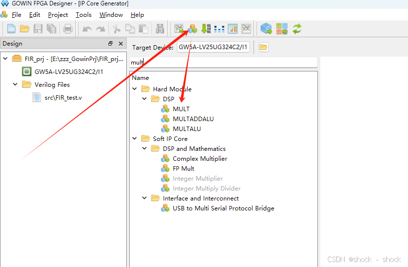
通过上图步骤,双击MULT,来创建乘法器模块。
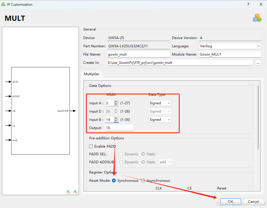
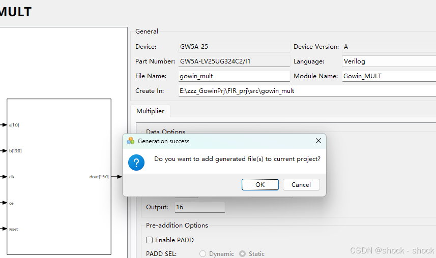
修改A和B的数据宽度,选择Synchronous(同步)复位后,点击OK后再点击OK。
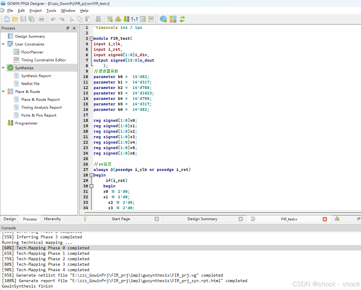
然后我们点击Process,鼠标右击Synthesize的run,如下图所示。
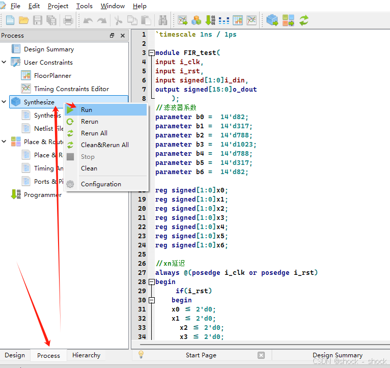
运行后无报错即可进入仿真阶段。
5.项目仿真
5.1 tb代码编写
我们再创建一个代码模块,命名为fir_tb。
仿真代码如下:
Matlab
`timescale 1ns / 1ps

module test_fir;
reg i_clk;
reg i_rst;
reg signed[1:0]i_din;
wire signed[15:0]o_dout;

GSR GSR(.GSRI(1'b1));

FIR_test FIR_test_u(
.i_clk              (i_clk),
.i_rst              (i_rst),
.i_din              (i_din),
.o_dout             (o_dout)
);

initial
begin
i_clk=1'b1;
i_rst=1'b1;
i_din=2'b00;
#1000
i_rst=1'b0;

i_din=2'b01;


#10
i_din=2'b00;

#30
i_din=2'b01;
#10
i_din=2'b00;

#30
i_din=2'b01;
#10
i_din=2'b00;

#30
i_din=2'b01;
#10
i_din=2'b00;

#30
i_din=2'b11;
#10
i_din=2'b00;


#30
i_din=2'b01;
#10
i_din=2'b00;

#30
i_din=2'b11;
#10
i_din=2'b00;

#30
i_din=2'b11;
#10
i_din=2'b00;

#30
i_din=2'b11;
#10
i_din=2'b00;

#30
i_din=2'b01;
#10
i_din=2'b00;
#30
i_din=2'b01;
#10
i_din=2'b00;

#30
i_din=2'b01;
#10
i_din=2'b00;

#30
i_din=2'b01;
#10
i_din=2'b00;

#30
i_din=2'b11;
#10
i_din=2'b00;


#30
i_din=2'b01;
#10
i_din=2'b00;

#30
i_din=2'b11;
#10
i_din=2'b00;

#30
i_din=2'b11;
#10
i_din=2'b00;

#30
i_din=2'b11;
#10
i_din=2'b00;

#30
i_din=2'b01;
#10
i_din=2'b00;

end

always #5 i_clk=~i_clk;


endmodule
同样的,ctrl+s保存仿真代码
5.2 modelsim仿真波形
将波形选择为有符号的十进制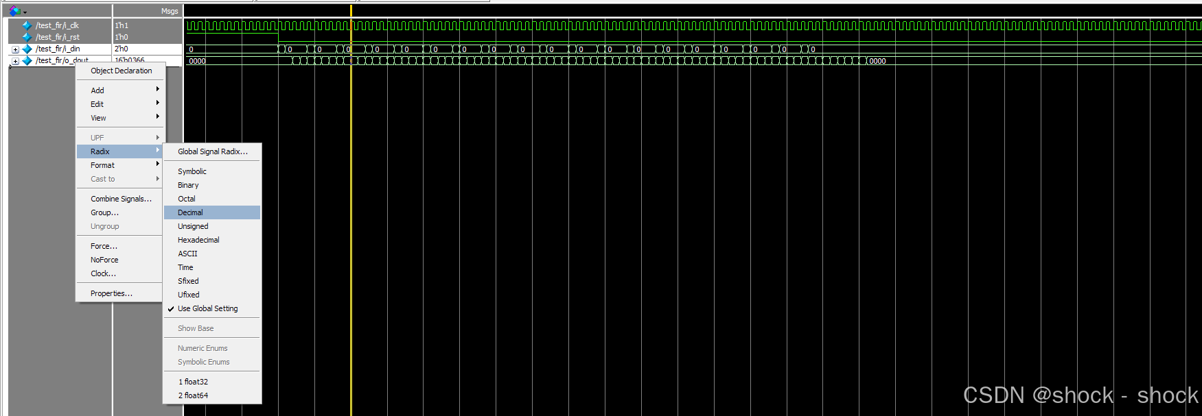
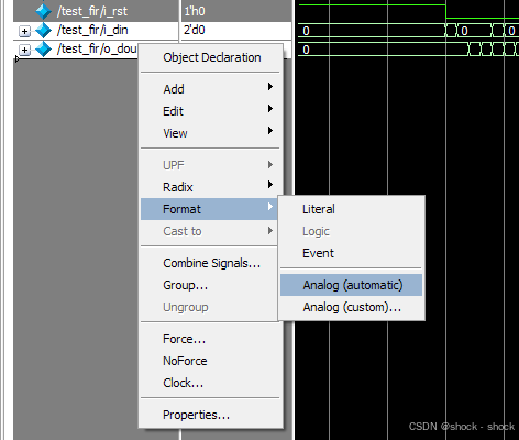
更改为模拟显示
更改后的波形如下图所示:
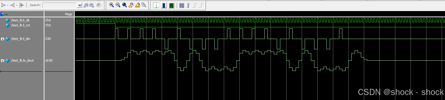
如上图所示就是使用fir滤波器的波形效果!