STM32基础外设开发:从点灯到传感器控制
一、前言
本篇文章总结STM32F10x系列基础外设开发实例,涵盖GPIO控制、按键检测、传感器应用等。所有代码基于标准库开发,适合STM32初学者参考。
二、硬件准备
- STM32F10x系列开发板
- LED模块
- 有源蜂鸣器
- 光敏电阻模块
- 按键模块
三、基础GPIO控制
1. 点灯实验
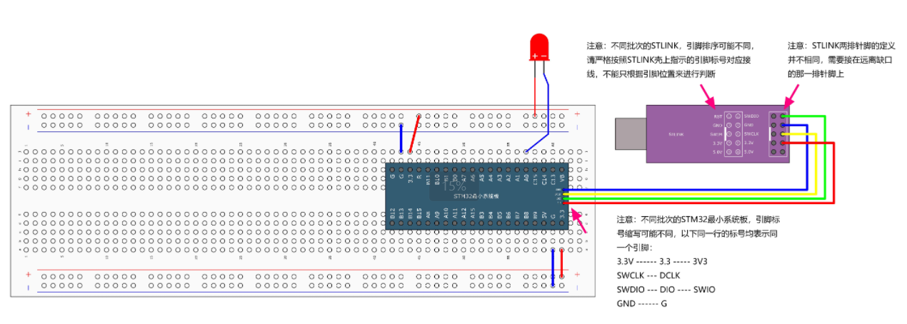
c
// 核心代码片段
RCC_APB2PeriphClockCmd(RCC_APB2Periph_GPIOA, ENABLE);

GPIO_InitTypeDef GPIO_InitStructure;
GPIO_InitStructure.GPIO_Mode = GPIO_Mode_Out_PP;
GPIO_InitStructure.GPIO_Pin = GPIO_Pin_0;
GPIO_InitStructure.GPIO_Speed = GPIO_Speed_50MHz;
GPIO_Init(GPIOA, &GPIO_InitStructure);

while(1) {
    GPIO_WriteBit(GPIOA, GPIO_Pin_0, Bit_RESET);
    Delay_ms(500);
    GPIO_WriteBit(GPIOA, GPIO_Pin_0, Bit_SET);
    Delay_ms(500);
}
关键点:
必须开启对应GPIO时钟 :选择你面包板插入对应的端口
推挽输出模式适合驱动LED
使用Delay函数实现定时控制
c
#include "stm32f10x.h"

/**
  * @brief  微秒级延时
  * @param  xus 延时时长,范围:0~233015
  * @retval 无
  */
void Delay_us(uint32_t xus)
{
	SysTick->LOAD = 72 * xus;				//设置定时器重装值
	SysTick->VAL = 0x00;					//清空当前计数值
	SysTick->CTRL = 0x00000005;				//设置时钟源为HCLK,启动定时器
	while(!(SysTick->CTRL & 0x00010000));	//等待计数到0
	SysTick->CTRL = 0x00000004;				//关闭定时器
}

/**
  * @brief  毫秒级延时
  * @param  xms 延时时长,范围:0~4294967295
  * @retval 无
  */
void Delay_ms(uint32_t xms)
{
	while(xms--)
	{
		Delay_us(1000);
	}
}

/**
  * @brief  秒级延时
  * @param  xs 延时时长,范围:0~4294967295
  * @retval 无
  */
void Delay_s(uint32_t xs)
{
	while(xs--)
	{
		Delay_ms(1000);
	}
}
2. 流水灯实验
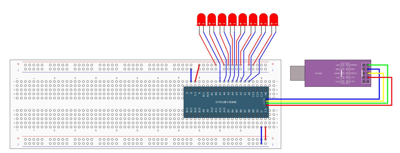
c
#include "stm32f10x.h"                  // Device header
#include "Delay.h"

int main(void)
{
	RCC_APB2PeriphClockCmd(RCC_APB2Periph_GPIOA, ENABLE);

	GPIO_InitTypeDef GPIO_InitStructure;
	GPIO_InitStructure.GPIO_Mode = GPIO_Mode_Out_PP;
	GPIO_InitStructure.GPIO_Pin = GPIO_Pin_All;
	GPIO_InitStructure.GPIO_Speed = GPIO_Speed_50MHz;
	GPIO_Init(GPIOA, &GPIO_InitStructure);

	while (1)
	{
		GPIO_Write(GPIOA, ~0x0001);	//0000 0000 0000 0001
		Delay_ms(100);
		GPIO_Write(GPIOA, ~0x0002);	//0000 0000 0000 0010
		Delay_ms(100);
		GPIO_Write(GPIOA, ~0x0004);	//0000 0000 0000 0100
		Delay_ms(100);
		GPIO_Write(GPIOA, ~0x0008);	//0000 0000 0000 1000
		Delay_ms(100);
		GPIO_Write(GPIOA, ~0x0010);	//0000 0000 0001 0000
		Delay_ms(100);
		GPIO_Write(GPIOA, ~0x0020);	//0000 0000 0010 0000
		Delay_ms(100);
		GPIO_Write(GPIOA, ~0x0040);	//0000 0000 0100 0000
		Delay_ms(100);
		GPIO_Write(GPIOA, ~0x0080);	//0000 0000 1000 0000
		Delay_ms(100);
	}
}

/*优化
void LED_Flow() {
    uint16_t ledPins = 0x0001;  // 从PA0开始
    while (1) {
        GPIO_Write(GPIOA, ~ledPins);  // 取反实现低电平点亮
        Delay_ms(200);
        ledPins <<= 1;                // 左移切换LED
        if (ledPins > 0x0080) {       // 到PA7后重置
            ledPins = 0x0001;
        }
    }
}*/
3.蜂鸣器
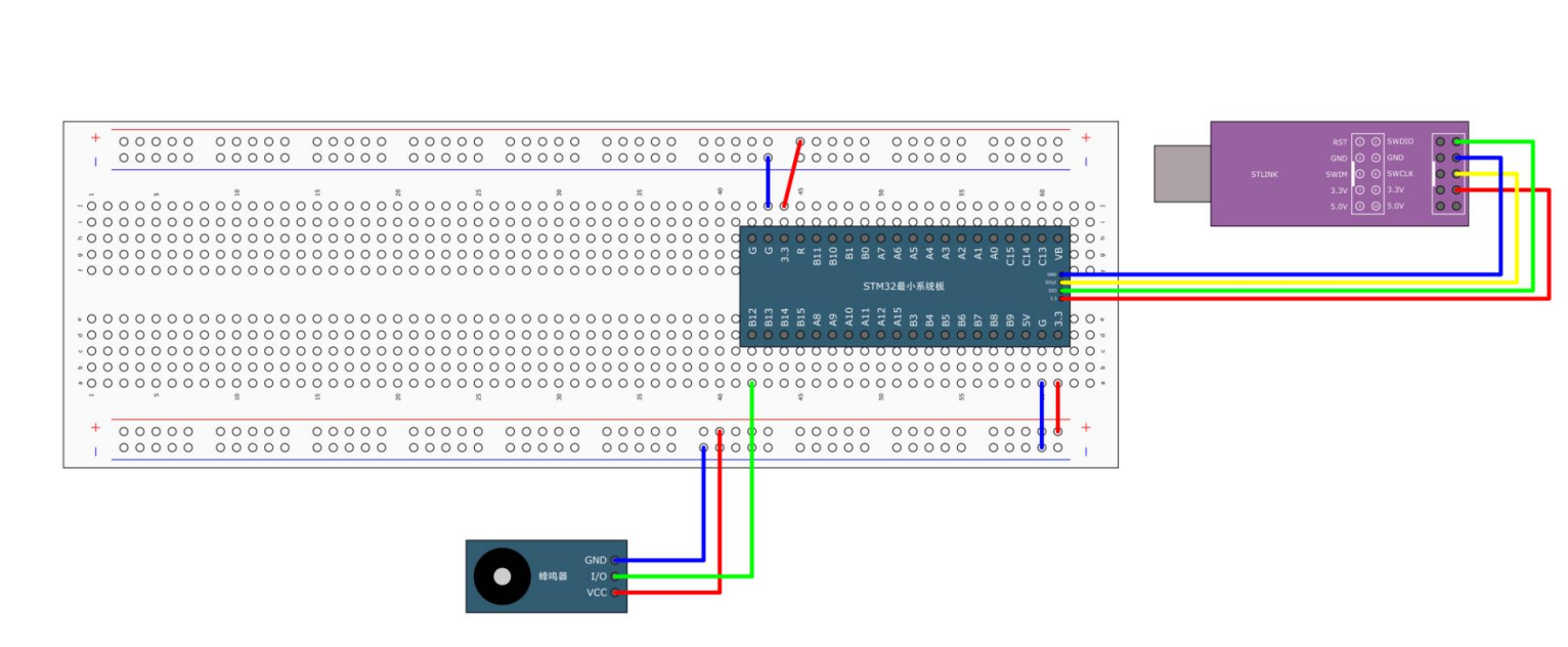
c
#include "stm32f10x.h"                  // Device header
#include "Delay.h"

int main(void)
{
	RCC_APB2PeriphClockCmd(RCC_APB2Periph_GPIOB, ENABLE);

	GPIO_InitTypeDef GPIO_InitStructure;
	GPIO_InitStructure.GPIO_Mode = GPIO_Mode_Out_PP;
	GPIO_InitStructure.GPIO_Pin = GPIO_Pin_12;
	GPIO_InitStructure.GPIO_Speed = GPIO_Speed_50MHz;
	GPIO_Init(GPIOB, &GPIO_InitStructure);

	while (1)
	{
		GPIO_ResetBits(GPIOB, GPIO_Pin_12);
		Delay_ms(100);
		GPIO_SetBits(GPIOB, GPIO_Pin_12);
		Delay_ms(100);
		GPIO_ResetBits(GPIOB, GPIO_Pin_12);
		Delay_ms(100);
		GPIO_SetBits(GPIOB, GPIO_Pin_12);
		Delay_ms(700);
	}
}
4.按键控制LED
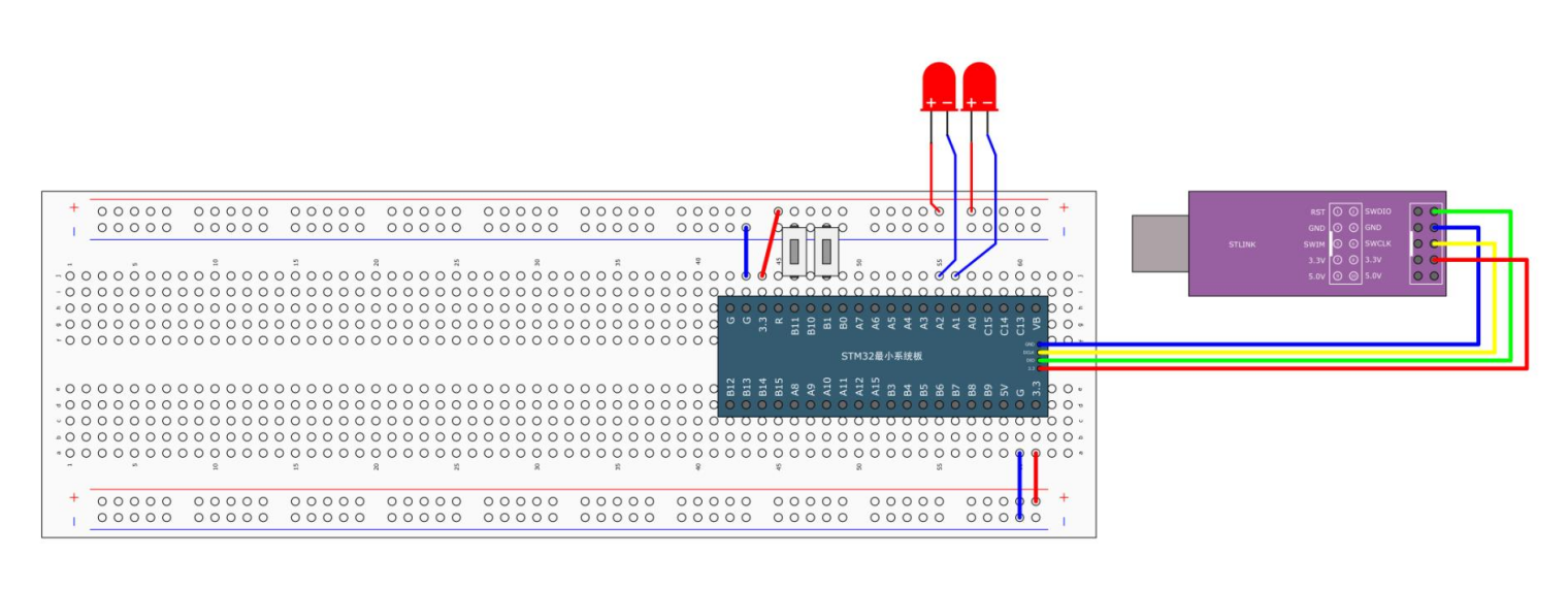
-
初始化LED,然后创建函数来控制了LED的亮灭,创建函数实现亮灭的翻转:当按下按键,读取led状态,高电平时是灭,然后然下按键,实现翻转,变亮
LED实现函数
c
#include "stm32f10x.h"                  // Device header

void LED_Init(void)
{
	RCC_APB2PeriphClockCmd(RCC_APB2Periph_GPIOA, ENABLE);

	GPIO_InitTypeDef GPIO_InitStructure;
	GPIO_InitStructure.GPIO_Mode = GPIO_Mode_Out_PP;
	GPIO_InitStructure.GPIO_Pin = GPIO_Pin_1 | GPIO_Pin_2;
	GPIO_InitStructure.GPIO_Speed = GPIO_Speed_50MHz;
	GPIO_Init(GPIOA, &GPIO_InitStructure);

	GPIO_SetBits(GPIOA, GPIO_Pin_1 | GPIO_Pin_2);
}

void LED1_ON(void)
{
	GPIO_ResetBits(GPIOA, GPIO_Pin_1);
}

void LED1_OFF(void)
{
	GPIO_SetBits(GPIOA, GPIO_Pin_1);
}

void LED1_Turn(void)
{
	if (GPIO_ReadOutputDataBit(GPIOA, GPIO_Pin_1) == 0)
	{
		GPIO_SetBits(GPIOA, GPIO_Pin_1);
	}
	else
	{
		GPIO_ResetBits(GPIOA, GPIO_Pin_1);
	}
}

void LED2_ON(void)
{
	GPIO_ResetBits(GPIOA, GPIO_Pin_2);
}

void LED2_OFF(void)
{
	GPIO_SetBits(GPIOA, GPIO_Pin_2);
}

void LED2_Turn(void)
{
	if (GPIO_ReadOutputDataBit(GPIOA, GPIO_Pin_2) == 0)
	{
		GPIO_SetBits(GPIOA, GPIO_Pin_2);
	}
	else
	{
		GPIO_ResetBits(GPIOA, GPIO_Pin_2);
	}
} 初始化按键,然后创建函数来读取按下按键的返回值
c
#include "stm32f10x.h"                  // Device header
#include "Delay.h"

void Key_Init(void)
{
	RCC_APB2PeriphClockCmd(RCC_APB2Periph_GPIOB, ENABLE);

	GPIO_InitTypeDef GPIO_InitStructure;
	GPIO_InitStructure.GPIO_Mode = GPIO_Mode_IPU;//上拉输入,默认高电平
	GPIO_InitStructure.GPIO_Pin = GPIO_Pin_1 | GPIO_Pin_11;
	GPIO_InitStructure.GPIO_Speed = GPIO_Speed_50MHz;
	GPIO_Init(GPIOB, &GPIO_InitStructure);
}

uint8_t Key_GetNum(void)
{
	uint8_t KeyNum = 0;
	if (GPIO_ReadInputDataBit(GPIOB, GPIO_Pin_1) == 0) //按下按键,低电平
	{
		Delay_ms(20);//延时消抖
		while (GPIO_ReadInputDataBit(GPIOB, GPIO_Pin_1) == 0);//如果不松开,循环卡住
		Delay_ms(20);//松开消抖
		KeyNum = 1;//控制led1,赋值
	}
	if (GPIO_ReadInputDataBit(GPIOB, GPIO_Pin_11) == 0)
	{
		Delay_ms(20);
		while (GPIO_ReadInputDataBit(GPIOB, GPIO_Pin_11) == 0);
		Delay_ms(20);
		KeyNum = 2;控制led2,赋值
	}

	return KeyNum;
}测试文件
c
#include "stm32f10x.h"                  // Device header
#include "Delay.h"
#include "LED.h"
#include "Key.h"

uint8_t KeyNum;

int main(void)
{
	LED_Init();
	Key_Init();

	while (1)
	{
		KeyNum = Key_GetNum();
		if (KeyNum == 1)
		{
			LED1_Turn();
		}
		if (KeyNum == 2)
		{
			LED2_Turn();
		}
	}
}
输入模式选择:
上拉输入(IPU):默认高电平,按键接地时触发低电平。
下拉输入(IPD):默认低电平,按键接VCC时触发高电平。
5.光明电阻控制LED(光线暗电阻高,高电平;反之低电平)
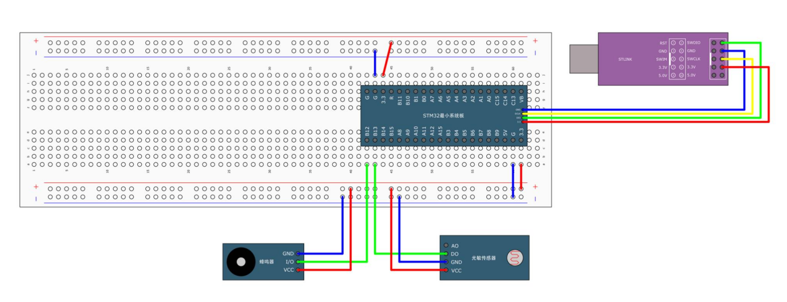
-
创建各自的实现文件,进行初始化操作,然后对蜂鸣器进行开关的操作实现(低电平响,高电平不响),然后光明电阻直接返回读出的输出值
蜂鸣器
c
#include "stm32f10x.h"                  // Device header

void Buzzer_Init(void)
{
	RCC_APB2PeriphClockCmd(RCC_APB2Periph_GPIOB, ENABLE);

	GPIO_InitTypeDef GPIO_InitStructure;
	GPIO_InitStructure.GPIO_Mode = GPIO_Mode_Out_PP;
	GPIO_InitStructure.GPIO_Pin = GPIO_Pin_12;
	GPIO_InitStructure.GPIO_Speed = GPIO_Speed_50MHz;
	GPIO_Init(GPIOB, &GPIO_InitStructure);

	GPIO_SetBits(GPIOB, GPIO_Pin_12);
}

void Buzzer_ON(void)
{
	GPIO_ResetBits(GPIOB, GPIO_Pin_12);
}

void Buzzer_OFF(void)
{
	GPIO_SetBits(GPIOB, GPIO_Pin_12);
}

void Buzzer_Turn(void)
{
	if (GPIO_ReadOutputDataBit(GPIOB, GPIO_Pin_12) == 0)
	{
		GPIO_SetBits(GPIOB, GPIO_Pin_12);
	}
	else
	{
		GPIO_ResetBits(GPIOB, GPIO_Pin_12);
	}
}光明电阻
c
#include "stm32f10x.h"                  // Device header

void LightSensor_Init(void)
{
	RCC_APB2PeriphClockCmd(RCC_APB2Periph_GPIOB, ENABLE);

	GPIO_InitTypeDef GPIO_InitStructure;
	GPIO_InitStructure.GPIO_Mode = GPIO_Mode_IPU;
	GPIO_InitStructure.GPIO_Pin = GPIO_Pin_13;
	GPIO_InitStructure.GPIO_Speed = GPIO_Speed_50MHz;
	GPIO_Init(GPIOB, &GPIO_InitStructure);
}

uint8_t LightSensor_Get(void)
{
	return GPIO_ReadInputDataBit(GPIOB, GPIO_Pin_13);
}测试文件
c
#include "stm32f10x.h"                  // Device header
#include "Delay.h"
#include "Buzzer.h"
#include "LightSensor.h"

int main(void)
{
	Buzzer_Init();
	LightSensor_Init();

	while (1)
	{
		if (LightSensor_Get() == 1)
		{
			Buzzer_ON();
		}
		else
		{
			Buzzer_OFF();
		}
	}
}