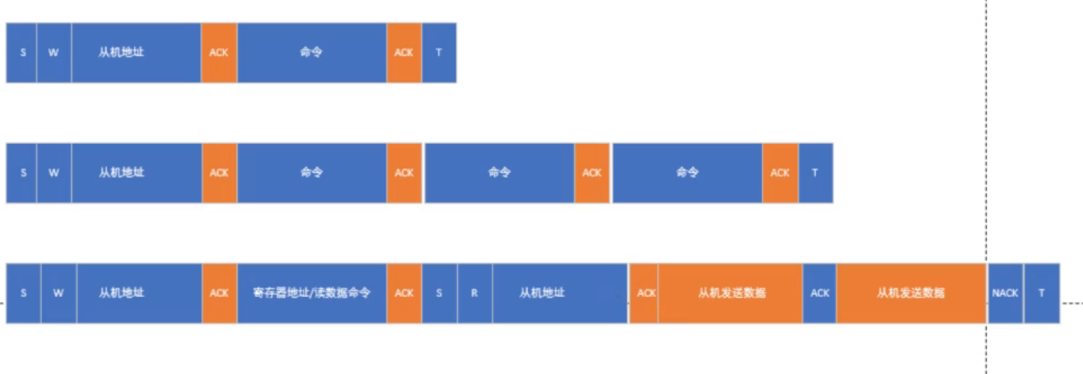
i2c时序
1. bmp280传感器基本控制寄存器
(1)测量控制寄存器(0xF4)
- 功能:配置温度/压力采样精度和工作模式。
- 位定义 :
- bit 7:5 (
osrs_t):温度过采样设置(0-5对应关闭/1x/2x/4x/8x/16x) - bit 4:2 (
osrs_p压力过采样设置(同上) - bit 1:0 (
mode):工作模式(00=休眠,01=强制模式,11=正常模式)
- bit 7:5 (
(2)配置寄存器(0xF5)
- 功能:设置滤波器和数据输出速率。
- 位定义 :
- bit 7:5 (
t_sb):待机时间(0-7对应0.5ms-4000ms) - bit 4:2 (
filter):IIR滤波系数(0-4对应关闭/2/4/8/16) - bit 0 (
spi3w_en):SPI三线模式使能(I2C模式下保持0)
- bit 7:5 (
2. 状态与识别寄存器
(3)状态寄存器(0xF3)
- 功能:指示传感器当前状态。
- 位定义 :
- bit 3 (
measuring):1表示正在测量(数据未就绪) - bit 0 (
im_update):1表示校准参数正在更新
- bit 3 (
(4)芯片ID寄存器(0xD0)
- 功能 :验证设备型号,固定值为
0x58(BMP280标识符)
(5)复位寄存器(0xE0)
- 功能 :写入
0xB6触发软复位,恢复默认配置
3. 数据寄存器
(6)压力数据寄存器(0xF7-0xF9)
- 地址 :
0xF7(MSB)、0xF8(LSB)、0xF9(XLSB) - 功能:存储20位原始压力数据(需左移4位对齐)
(7)温度数据寄存器(0xFA-0xFC)
- 地址 :
0xFA(MSB)、0xFB(LSB)、0xFC(XLSB) - 功能:存储20位原始温度数据(需左移4位对齐)
4. 校准参数寄存器(0x88-0xA1)
- 功能:存储出厂校准系数(共26个寄存器),用于温度和压力数据的补偿计算。
- 关键参数 :
dig_T1-T3:温度补偿系数(无符号16位/有符号16位)dig_P1-P9:压力补偿系数(混合类型)
I2C时序控制要点
- 地址选择 :
- SDO引脚电平决定I2C地址:低电平为
0x76,高电平为0x77。
- SDO引脚电平决定I2C地址:低电平为
- 读写时序 :
- 写操作:发送设备地址(写模式)+寄存器地址+数据。
- 读操作:先发送寄存器地址,再启动重复起始条件读取数据。
- 典型流程 :
- 复位 → 读取校准参数 → 配置采样模式 → 轮询状态寄存器 → 读取数据。
数据处理代码:主要读取原始数据包括3字节压力数据(20位)、3字节温度数据(20位)还有26字节校准数据:
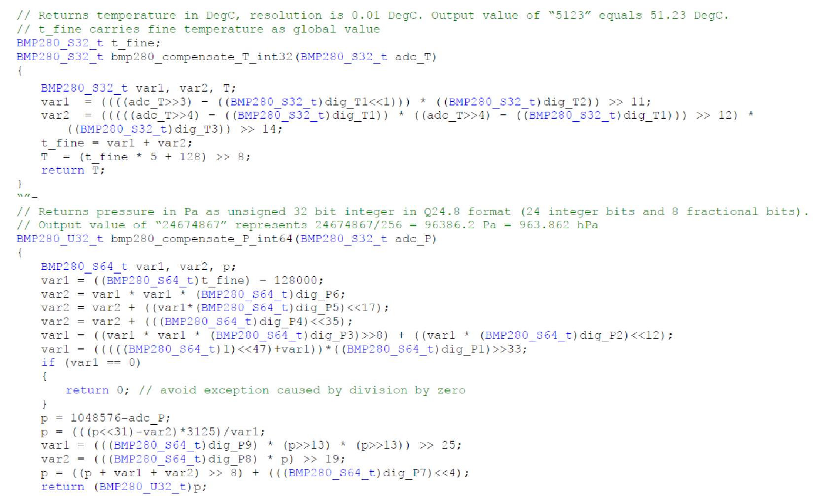
手册数据处理代码
BMP280的数据寄存器结构
BMP280的温度和压力ADC值均为20位数据,存储格式如下:
- 温度数据寄存器 (
0xFA-0xFC):0xFA(MSB):高8位0xFB(LSB):中8位0xFC(XLSB):低4位(有效位在bit7-4,其余位无效)
- 压力数据寄存器 (
0xF7-0xF9):- 类似温度寄存器,但压力值的XLSB在
0xF9中。
- 类似温度寄存器,但压力值的XLSB在
2. 原始数据组合方法
假设通过I2C读取的3字节数据为 [msb, lsb, xlsb],需按以下步骤处理:
// 组合成20位原始值(左对齐,低4位无效)
uint32_t raw_data = ((uint32_t)msb << 12) | ((uint32_t)lsb << 4) | (xlsb >> 4);- 左对齐特性:BMP280的ADC值默认左对齐(即高20位有效),因此无需右移补零。
- 低4位处理 :
xlsb的低4位是无效数据,需右移4位丢弃。
3. 调用函数时的传参
-
正确做法 :传入组合后的20位原始值(直接传
raw_data):int32_t adc_T = (int32_t)raw_data; // 转换为有符号整数 int32_t compensated_temp = bmp280_compensate_T_int32(adc_T); -
错误做法:直接传入未处理的字节数组首地址(函数内部无法解析3字节分散数据)。
4. 为什么函数内部还需要移位?
- 函数内移位 (如
adc_T >> 3)是补偿算法的要求,用于对齐校准公式的位宽。 - 传参前移位是为了将3字节数据合并为完整的20位原始值,二者目的不同。
示例代码(完整流程)
// 从传感器读取3字节温度数据(假设已通过I2C读取)
uint8_t temp_data[3] = {0x12, 0x34, 0x50}; // msb, lsb, xlsb

// 组合成20位原始值(左对齐)
uint32_t raw_temp = ((uint32_t)temp_data[0] << 12) | ((uint32_t)temp_data[1] << 4) | (temp_data[2] >> 4);

// 转换为有符号整数并传入补偿函数
int32_t adc_T = (int32_t)raw_temp;
int32_t temperature = bmp280_compensate_T_int32(adc_T);  // 单位:0.01°C
关键总结
- 必须组合数据:调用函数前需将3字节合并为20位原始值(左对齐)。
- 无需额外移位:传入的是完整20位值,函数内部会处理校准所需的移位。
- 数据有效性 :确保丢弃
xlsb的低4位无效数据。
代码分析总结
1. 代码功能
这段代码实现了BMP280传感器的温度和压力数据补偿计算,主要包含两个函数:
bmp280_compensate_T_int32:计算温度值(单位:0.01°C)bmp280_compensate_P_int64:计算压力值(单位:Pa,Q24.8格式)
2. 关键实现细节
温度计算:
-
输入:ADC原始温度值(
adc_T) -
输出:补偿后的温度值(分辨率0.01°C)
-
核心算法:
var1 = (((adc_T>>3) - (t_fine_dig_T1<<1)) * t_fine_dig_T2) >> 11;
var2 = ((((adc_T>>4) - t_fine_dig_T1)^2 >> 12) * t_fine_dig_T3) >> 14;
t_fine = var1 + var2;  // 存储到全局变量
T = (t_fine * 5 + 128) >> 8;  // 最终温度
压力计算:
-
输入:ADC原始压力值(
adc_P) -
输出:补偿后的压力值(Q24.8格式)
-
核心算法:
// 多阶段多项式补偿计算
var1 = t_fine - 128000;
var2 = var1^2 * t_fine_dig_P6 + (var1*t_fine_dig_P5<<17) + (t_fine_dig_P4<<35);
var1 = (var1^2*t_fine_dig_P3>>8) + (var1*t_fine_dig_P2<<12);
var1 = ((1<<47)+var1)*t_fine_dig_P1>>33;

p = 1048576 - adc_P;
p = (((p<<31)-var2)*3125)/var1;  // 注意防除零处理

// 二次补偿
p += ((t_fine_dig_P9*(p>>13)^2)>>25) + ((t_fine_dig_P8*p)>>19);
p = (p>>8) + (t_fine_dig_P7<<4);
3. 技术亮点
-
定点数优化:
- 全程使用整数运算(无浮点)
- 通过移位操作(
>>/<<)实现2的幂次乘除 - Q24.8格式处理压力值(24位整数+8位小数)
-
校准参数应用:
- 使用
t_fine_dig_T1-T3和t_fine_dig_P1-P9等传感器校准参数 - 温度补偿结果
t_fine会用于压力计算
- 使用
-
异常处理:
- 压力计算中对
var1==0的情况进行了保护
- 压力计算中对
4. 典型输出示例
- 温度:输出
5123表示51.23°C - 压力:输出
24674867表示96386.2 Pa(963.862 hPa)
1. 温度计算函数 bmp280_compensate_T_int32
参数与变量解析
| 名称 | 类型(实际) | 意义 | 数据来源 |
|---|---|---|---|
adc_T |
BMP280_S32_t(32位有符号整数) |
ADC原始温度值(20位数据左对齐,需右移4位使用) | 传感器寄存器0xFA-0xFC |
dig_T1 |
uint16_t |
温度校准系数1(无符号,用于线性补偿) | 校准寄存器0x88-0x89 |
dig_T2 |
int16_t |
温度校准系数2(有符号,用于一阶非线性补偿) | 校准寄存器0x8A-0x8B |
dig_T3 |
int16_t |
温度校准系数3(有符号,用于二阶非线性补偿) | 校准寄存器0x8C-0x8D |
var1/var2 |
BMP280_S32_t |
中间计算变量,存储补偿公式的中间结果 | 代码内部计算 |
t_fine |
BMP280_S32_t |
全局变量,存储精细温度值,用于压力补偿计算 | 代码内部计算 |
| 返回值 | BMP280_S32_t |
补偿后温度值(单位:0.01°C,如5123表示51.23°C) |
公式计算 |
关键操作
-
位运算优化 :通过右移操作(
>>3/>>4)对齐ADC数据位,避免浮点运算。 -
校准公式 :
t_fine = var1 + var2;  // var1为线性补偿项,var2为非线性补偿项
T = (t_fine * 5 + 128) >> 8;  // 转换为0.01°C分辨率
2. 压力计算函数 bmp280_compensate_P_int64
参数与变量解析
| 名称 | 类型(实际) | 意义 | 数据来源 |
|---|---|---|---|
adc_P |
BMP280_S32_t(32位有符号整数) |
ADC原始压力值(20位数据左对齐,需右移4位使用) | 传感器寄存器0xF7-0xF9 |
dig_P1-P9 |
混合类型(uint16_t/int16_t) |
压力校准系数(P1无符号,P2-P9有符号),用于多阶段多项式补偿 | 校准寄存器0x8E-0x9F |
var1/var2 |
BMP280_S64_t(64位有符号整数) |
中间计算变量,处理大数运算以避免溢出 | 代码内部计算 |
p |
BMP280_S64_t |
补偿过程中的压力中间值,最终转换为Q24.8格式 | 代码内部计算 |
| 返回值 | BMP280_U32_t(32位无符号整数) |
补偿后压力值(Q24.8格式,如24674867表示96386.2 Pa) |
公式计算 |
关键操作
-
64位整数运算 :处理大范围数值(如
<<35)和防止溢出。 -
Q24.8格式转换 :通过移位和除法实现定点数小数部分保留:
p = ((p + var1 + var2) >> 8) + (dig_P7 << 4); // 最终转换为24.8格式 -
防除零保护 :检查
var1==0避免异常。
3. 校准参数的意义与作用
| 参数组 | 功能 | 寄存器地址范围 |
|---|---|---|
dig_T1-T3 |
补偿温度传感器的非线性误差,包括偏移量、灵敏度漂移等 | 0x88-0x8D |
dig_P1-P9 |
补偿压力传感器的温度漂移和非线性特性,通过多项式拟合提高精度 | 0x8E-0x9F |
设备树编写:
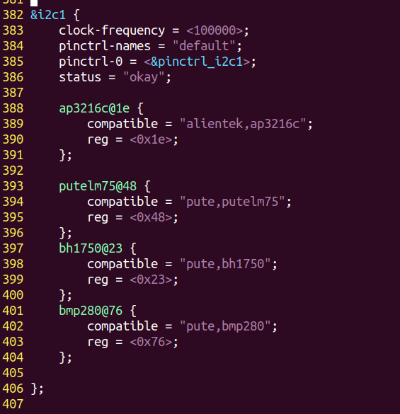
直接在i2c设备节点下加入我们的设备子节点,主要写上设备地值和compatible属性,地址根据sdo接线判断,接地0x76,接vcc 0x77。
驱动编写:
#include <asm/io.h>
#include <asm/uaccess.h>
#include <linux/cdev.h>
#include <linux/delay.h>
#include <linux/device.h>
#include <linux/fs.h>
#include <linux/i2c.h>
#include <linux/init.h>
#include <linux/io.h>
#include <linux/miscdevice.h>
#include <linux/module.h>
#include <linux/mutex.h>
#include <linux/of.h>
#include <linux/of_address.h>
#include <linux/of_gpio.h>
#include <linux/platform_device.h>
#include <linux/string.h>

static struct i2c_client *bmp280_client;

static ssize_t bmp280_read(struct file *fp, char __user *puser, size_t n,
                         loff_t *off)
{
  int ret;
  int i;
  struct i2c_msg msg;
  char data[2];
  char buf1[6] = {0};//存温度压力
  char buf2[26] = {0};//存校准参数
  char buf[32] = {0};
//传感器复位
  data[0] = 0xE0;//复位寄存器地址
  data[1] = 0xB6;//要写的数据
  msg.addr = bmp280_client->addr;//从机地址
  msg.flags = 0;//0写,1读
  msg.buf = data;
  msg.len = 2;//长度2个字节,表示把data数组的前两个数据写入
  bmp280_client->adapter->algo->master_xfer(bmp280_client->adapter, &msg, 1);//调用函数接口传输msg消息

//启动测量
  data[0] = 0xF4;//测量控制寄存器(0xF4)
  data[1] = 0x27;//要写的数据
  msg.addr = bmp280_client->addr;//从机地址
  msg.flags = 0;//0写,1读
  msg.buf = data;
  msg.len = 2;//长度2个字节,表示把data数组的前两个数据写入
  bmp280_client->adapter->algo->master_xfer(bmp280_client->adapter, &msg, 1);//调用函数接口传输msg消息
  msleep(10);
//读取传感器校准参数
  data[0] = 0x88;//校准参数寄存器(0x88-0xA1),总共26个
  msg.addr = bmp280_client->addr;//从机地址
  msg.flags = 0;//0写
  msg.buf = data;
  msg.len = 1;//长度2个字节,表示把data数组的前两个数据写入
  bmp280_client->adapter->algo->master_xfer(bmp280_client->adapter, &msg, 1);//调用函数接口传输msg消息

  msg.addr = bmp280_client->addr;
  msg.flags = I2C_M_RD;
  msg.buf = buf2;//把校准参数读到data
  msg.len = 26;
  bmp280_client->adapter->algo->master_xfer(bmp280_client->adapter, &msg, 1);


//读取温度、压强数据
  data[0] = 0xF7;//压力数据寄存器(0xF7-0xF9)温度数据寄存器(0xFA-0xFC)
  msg.addr = bmp280_client->addr;//从机地址
  msg.flags = 0;//0写,1读
  msg.buf = data;
  msg.len = 1;
  bmp280_client->adapter->algo->master_xfer(bmp280_client->adapter, &msg, 1);//调用函数接口传输msg消息

  msg.addr = bmp280_client->addr;
  msg.flags = I2C_M_RD;
  msg.buf = buf1;
  msg.len = 6;
  bmp280_client->adapter->algo->master_xfer(bmp280_client->adapter, &msg, 1);

  //buf1[6] + buf2[26] -->buf[32]
  for(i = 0;i < 6;++i)
  {
    buf[i] = buf1[i];
  }
  for(i = 6;i < 32;++i)
  {
    buf[i] = buf2[i - 6];
  }
  ret = copy_to_user(puser, buf, sizeof(buf));
  return sizeof(buf);
}

//文件开关/////////////////
static int bmp280_open(struct inode *node, struct file *fp)
{
  pr_info("open success\n");
  return 0;
}
static int bmp280_release(struct inode *node, struct file *fp)
{
  pr_info("release success\n");
  return 0;
}
///////////////////////////OK

//文件操作函数结构体//////
static struct file_operations fops = {
    .owner = THIS_MODULE,  //计数,表示有几个模块调用文件操作
    .open = bmp280_open,
    .release = bmp280_release,
    .read = bmp280_read,
};
//////////////OK

///注册混杂设备////////////////
static struct miscdevice misc_device = {
    .minor = MISC_DYNAMIC_MINOR,  //次设备号申请
    .name = "misc_bmp280",          //设备节点名
    .fops = &fops,                //绑定文件操作函数结构体
};
///////////////////OK

///////////probe///////////
static int bmp280_probe(struct i2c_client *pclient,
                      const struct i2c_device_id *pdevice)
{
  misc_register(&misc_device);

  bmp280_client = pclient;

  pr_info("bmp280_probe ok!\n");

  return 0;
}
/////////////////////NO

/////////remove///////
static int bmp280_remove(struct i2c_client *pclient)
{
  misc_deregister(&misc_device);
  pr_info("bmp280_remove ok!\n");

  return 0;
}
/////////////////////OK

// i2c设备驱动匹配////////////////
static struct of_device_id bmp280_of_match_table[] = {
    {.compatible = "pute,bmp280"},
    {},
};
static struct i2c_device_id bmp280_id_table[] = {
    {.name = "bmp280"},
    {},
};
static struct i2c_driver bmp280_i2c_drv = {
    .driver =
        {
            .name = "bmp280",
            .of_match_table = bmp280_of_match_table,
        },
    .id_table = bmp280_id_table,
    .probe = bmp280_probe,
    .remove = bmp280_remove,
};
//////////////////////////////OK

//驱动入口内调函数//////////
static int __init bmp280_init(void)
{
  //注册i2c设备驱动
  i2c_register_driver(THIS_MODULE, &bmp280_i2c_drv);
  pr_info("bmp280 init success\n");
  return 0;
}

//驱动出口内调函数
static void __exit bmp280_exit(void)
{
  //销毁i2c设备驱动
  i2c_del_driver(&bmp280_i2c_drv);
  pr_info("bmp280 exit success\n");
  return;
}
/////////////////OK

//驱动入口
module_init(bmp280_init);
//驱动出口
module_exit(bmp280_exit);

MODULE_LICENSE("GPL");
驱动的读时序遇到的大问题:
以前的传感器都是直接读写寄存器,发指令,没加延时等待,但这次的bmp280传感器启动测量后必须加延时等待测量完成再采集数据,否则只会采集的0x80000 等无效数据,切记,以后要仔细查看传感器手册相关时序要求。
已经采集到原始数据了,接下来根据前面手册提供的数据处理函数进行自己的测试程序编写:
必须利用校验数据结合原始数据进行计算才能得到准确压强值。
#include <stdio.h>
#include <sys/types.h>
#include <sys/stat.h>
#include <fcntl.h>
#include <unistd.h>
#include <stdint.h>
#include <stdio.h>

typedef struct {
    uint16_t dig_T1;
    int16_t dig_T2;
    int16_t dig_T3;
    uint16_t dig_P1;
    int16_t dig_P2;
    int16_t dig_P3;
    int16_t dig_P4;
    int16_t dig_P5;
    int16_t dig_P6;
    int16_t dig_P7;
    int16_t dig_P8;
    int16_t dig_P9;
} BMP280_CalibData;

float process_bmp280_data(unsigned char *buf) {
    // 1. 解析温度和气压原始数据
    uint32_t press_raw = ((uint32_t)buf[0] << 12) | ((uint32_t)buf[1] << 4) | ((uint32_t)buf[2] >> 4);
    uint32_t temp_raw = ((uint32_t)buf[3] << 12) | ((uint32_t)buf[4] << 4) | ((uint32_t)buf[5] >> 4);

    // 2. 解析校准参数
    BMP280_CalibData calib;
    calib.dig_T1 = (uint16_t)(buf[6] | (buf[7] << 8));
    calib.dig_T2 = (int16_t)(buf[8] | (buf[9] << 8));
    calib.dig_T3 = (int16_t)(buf[10] | (buf[11] << 8));
    calib.dig_P1 = (uint16_t)(buf[12] | (buf[13] << 8));
    calib.dig_P2 = (int16_t)(buf[14] | (buf[15] << 8));
    calib.dig_P3 = (int16_t)(buf[16] | (buf[17] << 8));
    calib.dig_P4 = (int16_t)(buf[18] | (buf[19] << 8));
    calib.dig_P5 = (int16_t)(buf[20] | (buf[21] << 8));
    calib.dig_P6 = (int16_t)(buf[22] | (buf[23] << 8));
    calib.dig_P7 = (int16_t)(buf[24] | (buf[25] << 8));
    calib.dig_P8 = (int16_t)(buf[26] | (buf[27] << 8));
    calib.dig_P9 = (int16_t)(buf[28] | (buf[29] << 8));

    // 3. 计算温度
    int32_t var1, var2, t_fine;
    var1 = ((((temp_raw >> 3) - ((int32_t)calib.dig_T1 << 1))) * ((int32_t)calib.dig_T2)) >> 11;
    var2 = (((((temp_raw >> 4) - ((int32_t)calib.dig_T1)) * ((temp_raw >> 4) - ((int32_t)calib.dig_T1))) >> 12) * ((int32_t)calib.dig_T3)) >> 14;
    t_fine = var1 + var2;
    float temperature = (float)((t_fine * 5 + 128) >> 8) / 100.0f;

    // 4. 计算气压
    int64_t var1_p, var2_p, p;
    var1_p = ((int64_t)t_fine) - 128000;
    var2_p = var1_p * var1_p * (int64_t)calib.dig_P6;
    var2_p = var2_p + ((var1_p * (int64_t)calib.dig_P5) << 17);
    var2_p = var2_p + (((int64_t)calib.dig_P4) << 35);
    var1_p = ((var1_p * var1_p * (int64_t)calib.dig_P3) >> 8) + ((var1_p * (int64_t)calib.dig_P2) << 12);
    var1_p = ((((int64_t)1) << 47) + var1_p) * ((int64_t)calib.dig_P1) >> 33;

    if (var1_p == 0) {
        return 1; // 避免除以0
    }

    p = 1048576 - press_raw;
    p = (((p << 31) - var2_p) * 3125) / var1_p;
    var1_p = (((int64_t)calib.dig_P9) * (p >> 13) * (p >> 13)) >> 25;
    var2_p = (((int64_t)calib.dig_P8) * p) >> 19;
    p = ((p + var1_p + var2_p) >> 8) + (((int64_t)calib.dig_P7) << 4);
    float pressure = (float)p / 25600.0f;

    // 5. 输出结果
    return pressure;
}


int main(void)
{
    int fd = 0;
    unsigned char buf[32];//存放原始数据
    int temp,press,i;
    short cal[12];
    fd = open("/dev/misc_bmp280", O_RDWR);
    if (-1 == fd)
    {
        perror("fail to open");
        return -1;
    }

    while (1)
    {
        read(fd, &buf, sizeof(buf));//接收传来的温度压力buf[0]-buf[5],校准参数buf[6]-buf[31];
        printf("press:%fhpa\n",process_bmp280_data(buf));
        sleep(1);
    }
    close(fd);

    return 0;
}