LVI-SAM的VIS提取视觉特征点,得到特征点的归一化平面坐标(归一化平面位于相机光心前方Z=1处 )。接下来将视觉特征点的归一化平面坐标投影到单位球上,也就是对归一化平面坐标再进行一次归一化,使坐标向量模长为1,得到的单位向量仅代表特征点相对于相机光心的方向:
cpp
pcl::PointCloud<PointType>::Ptr features_3d_sphere(new pcl::PointCloud<PointType>());
for (int i = 0; i < (int)features_2d.size(); ++i)
{
    // normalize 2d feature to a unit sphere
    Eigen::Vector3f feature_cur(features_2d[i].x, features_2d[i].y, features_2d[i].z); // z always equal to 1
    feature_cur.normalize();

    // carema --> lidar
    PointType p;
    p.x =  feature_cur(2);
    p.y = -feature_cur(0);
    p.z = -feature_cur(1);
    p.intensity = -1;     // intensity will be used to save depth
    features_3d_sphere->push_back(p);
}代码中还将相机坐标系的点转换到雷达坐标系。因为通常相机的Z轴指向正前方,激光雷达的Z轴指向正上方,如图所示:
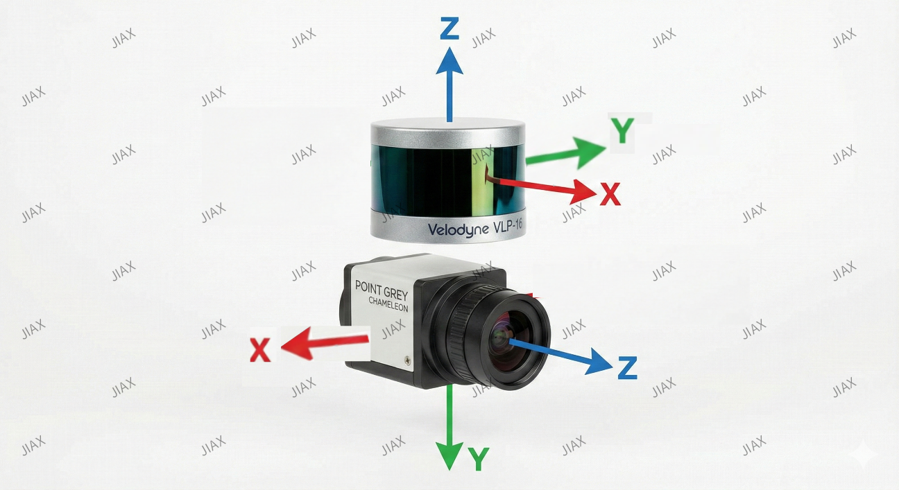
与此同时,获取缓存的5s内的地图中机器人附近的激光点云,并根据此时的相机在世界坐标系中的位姿将点云转换到相机坐标系。接下来构造激光点云的深度直方图对激光点云按照角度进行下采样。
具体而言,将相机方向正前方水平180度(-90度到+90度)、垂直180度(-90度到+90度)按照0.5度/格的分辨率划分为360x360的二维数组。然后遍历激光点云计算每个点的俯仰角(点与平面Z=0的夹角)与方位角(点与平面X=0的夹角),再用角度 除以分辨率 得到点在深度直方图中的二维索引:
cpp
for (int i = 0; i < (int)depth_cloud_local->size(); ++i)
{
    PointType p = depth_cloud_local->points[i];
    // filter points not in camera view
    if (p.x < 0 || abs(p.y / p.x) > 10 || abs(p.z / p.x) > 10)
        continue;

    // 行索引:俯仰角(上下方向)→ 映射到 0~num_bins
    float row_angle = atan2(p.z, sqrt(p.x * p.x + p.y * p.y)) * 180.0 / M_PI + 90.0; // degrees, bottom -> up, 0 -> 360
    int row_id = round(row_angle / bin_res);
    // 列索引:方位角(左右方向)→ 映射到 0~num_bins
    float col_angle = atan2(p.x, p.y) * 180.0 / M_PI; // degrees, left -> right, 0 -> 360
    int col_id = round(col_angle / bin_res);
    // id may be out of boundary
    if (row_id < 0 || row_id >= num_bins || col_id < 0 || col_id >= num_bins)
        continue; // 超出索引范围

    // only keep points that's closer 仅仅保留最近的激光点深度
    float dist = pointDistance(p);
    if (dist < rangeImage.at<float>(row_id, col_id))
    {
        rangeImage.at<float>(row_id, col_id) = dist; // 深度
        pointsArray[row_id][col_id] = p;             // 激光点
    }
}因为可能有多个点投影到同一个格子,代码中比较了投影到同一个格子的点的深度,仅保存较近点。通过这样的操作,将激光点云根据角度方向分布完成了下采样。
接下来,同样对下采样得到的激光点云坐标进行归一化,将保留下来的激光点投影到单位球上:
cpp
// 提取深度直方图中过滤后的点云
pcl::PointCloud<PointType>::Ptr depth_cloud_local_filter2(new pcl::PointCloud<PointType>());
for (int i = 0; i < num_bins; ++i)
{
    for (int j = 0; j < num_bins; ++j)
    {
        if (rangeImage.at<float>(i, j) != FLT_MAX)
            depth_cloud_local_filter2->push_back(pointsArray[i][j]);
    }
}
*depth_cloud_local = *depth_cloud_local_filter2;

// 将保留下来的激光点投影到单位球上
pcl::PointCloud<PointType>::Ptr depth_cloud_unit_sphere(new pcl::PointCloud<PointType>());
for (int i = 0; i < (int)depth_cloud_local->size(); ++i)
{
    PointType p = depth_cloud_local->points[i];
    float range = pointDistance(p);
    p.x /= range;
    p.y /= range;
    p.z /= range;
    p.intensity = range;
    depth_cloud_unit_sphere->push_back(p);
}
if (depth_cloud_unit_sphere->size() < 10)
    return depth_of_point;
然后使用单位球面上的激光点云构造KDTree:
cpp
pcl::KdTreeFLANN<PointType>::Ptr kdtree(new pcl::KdTreeFLANN<PointType>());
kdtree->setInputCloud(depth_cloud_unit_sphere);
代码遍历投影至单位球面上的视觉特征点,利用 KDTree 搜索出单位球面上距离当前视觉特征点最近的三个激光点。球面投影示意图:
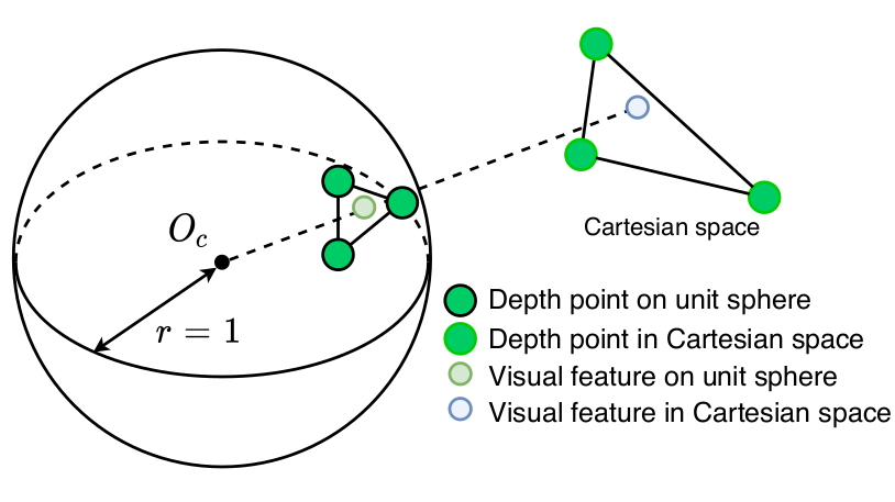
由于在单位球面上,点间距离本质上反映了射线之间的方向差异 (即夹角大小),这一步有效剔除了深度值的影响,实现了纯粹基于视线方向的关联。在锁定方向最接近的三个激光点后,代码恢复它们的真实三维坐标以构建局部平面,最后通过计算视觉射线与该平面的交点,从而估计出视觉特征点的深度:
cpp
// 在单位球上, 寻找与视觉特征点最近的三个激光点, 来估计视觉特征点的深度
vector<int> pointSearchInd;
vector<float> pointSearchSqDis;
// 设置匹配阈值(方向差异约束):将角度分辨率转换为单位球上的弧长 * 5,再求平方
// 效果:只有角度差异小于~2.5°(0.5°×5)的激光点才会被视为有效匹配。
float dist_sq_threshold = pow(sin(bin_res / 180.0 * M_PI) * 5.0, 2);
for (int i = 0; i < (int)features_3d_sphere->size(); ++i)
{
    kdtree->nearestKSearch(features_3d_sphere->points[i], 3, pointSearchInd, pointSearchSqDis);
    // 有效匹配判断:成功找到 3 个激光点,且最远的那个激光点的方向差异仍在阈值内(3 个点都在同一方向附近,确保平面拟合有效)。
    if (pointSearchInd.size() == 3 && pointSearchSqDis[2] < dist_sq_threshold)
    {
        // 单位球上最近的三个激光点 A B C (实际坐标)
        float r1 = depth_cloud_unit_sphere->points[pointSearchInd[0]].intensity; // A的深度
        Eigen::Vector3f A(depth_cloud_unit_sphere->points[pointSearchInd[0]].x * r1,
                            depth_cloud_unit_sphere->points[pointSearchInd[0]].y * r1,
                            depth_cloud_unit_sphere->points[pointSearchInd[0]].z * r1);

        float r2 = depth_cloud_unit_sphere->points[pointSearchInd[1]].intensity;
        Eigen::Vector3f B(depth_cloud_unit_sphere->points[pointSearchInd[1]].x * r2,
                            depth_cloud_unit_sphere->points[pointSearchInd[1]].y * r2,
                            depth_cloud_unit_sphere->points[pointSearchInd[1]].z * r2);

        float r3 = depth_cloud_unit_sphere->points[pointSearchInd[2]].intensity;
        Eigen::Vector3f C(depth_cloud_unit_sphere->points[pointSearchInd[2]].x * r3,
                            depth_cloud_unit_sphere->points[pointSearchInd[2]].y * r3,
                            depth_cloud_unit_sphere->points[pointSearchInd[2]].z * r3);

        // 视觉特征点在单位球上的坐标 V
        // https://math.stackexchange.com/questions/100439/determine-where-a-vector-will-intersect-a-plane
        Eigen::Vector3f V(features_3d_sphere->points[i].x,
                            features_3d_sphere->points[i].y,
                            features_3d_sphere->points[i].z);

        // 估计视觉特征点的深度 s
        // 向量 BA X CB,得到垂直于平面的法向量,其模长与平面内两个向量构成的平行四边形面积成正比。
        Eigen::Vector3f N = (A - B).cross(B - C);
        // NOTE:求深度s

        float s = (N(0) * A(0) + N(1) * A(1) + N(2) * A(2))  // (BA X CB) * OA
                / (N(0) * V(0) + N(1) * V(1) + N(2) * V(2)); // (BA X CB) * OV

        float min_depth = min(r1, min(r2, r3));
        float max_depth = max(r1, max(r2, r3));
        if (max_depth - min_depth > 2 || s <= 0.5)
        {
            continue;
        } else if (s - max_depth > 0) {
            s = max_depth;
        } else if (s - min_depth < 0) {
            s = min_depth;
        }
        // convert feature into cartesian space if depth is available
        features_3d_sphere->points[i].x *= s;
        features_3d_sphere->points[i].y *= s;
        features_3d_sphere->points[i].z *= s;
        // the obtained depth here is for unit sphere, VINS estimator needs depth for normalized feature (by value z), (lidar x = camera z)
        // 存储最终深度(激光系x轴对应相机前向,深度即x)
        // 因为激光点云转换到相机系后,前向点的 x 轴坐标(激光系)≈ 相机系的 z 轴坐标(光轴方向);
        // 视觉中所谓的"深度"就是点到相机光心的距离,即Z轴距离
        features_3d_sphere->points[i].intensity = features_3d_sphere->points[i].x; // ???
    }
}代码中恢复视觉特征点的深度s的过程如下:
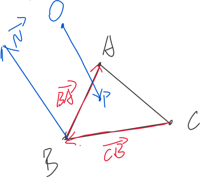
A、B、C为方向离视觉特征点P最近的三个激光点,三点可以拟合一个平面ABC。求射线OP与平面ABC的交点P,这个交点P到相机原点O的距离就是深度s,即。已知
的单位向量为
,则
。然后:
则平面的法向量:
且线段AP在平面ABC上,则垂直于
,即:
则:
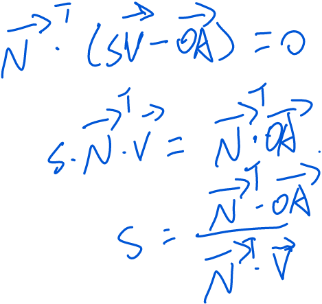
公式推导过程与代码一致。