【嵌入式linux学习】06_中断子系统
这个blog 默认对stm32裸机中断有一定的认识~
首先说说stm32的裸机的中断机制
我们都知道它有一个NVIC中断控制器。中断 = 外设 → NVIC → CPU,几乎没有中间层
在这里的步骤是
外设产生中断
→ NVIC 判断是否使能
→ NVIC 比较优先级
→ CPU 跳转到 ISR
→ 执行中断函数
→ 返回
在嵌入式linux里面:
外设中断信号
   ↓
GIC600(路由 / 优先级 / 目标 CPU)
   ↓
CPU 的异常入口(EL1 IRQ)
   ↓
Linux 中断子系统
   ↓
 request_irq() handler
GIC(Generic Interrupt Controller) 是:
ARM 为"多核 + 操作系统"设计的通用中断控制器
它不是 CPU 内部的一小块逻辑 ,而是一个独立的硬件模块。主要作用就是接受硬件中断信号,通过一定的设置策略,然后分发给对应的CPU进行处理。
以GIC v3为例,它主要处理不同的中断源:
- SGI (Software Generated Interrupt):软件触发的中断。软件可以通过写 GICD_SGIR寄存器来触发一个中断事件,一般用于核间通信,内核中的IPI:inter-processor interrupts 就是基于SGI。
- PPI (Private Peripheral Interrupt):私有外设中断,该终端来自于外设,被特定的核处理。GIC 是支持多核的,每个核有自己独有的中断。
- SPI (Shared Peripheral Interrupt):共享外设中断,所有核共享的中断。中断产生后,可以分发到某一个CPU上。
- LPI (Locality-specific Peripheral Interrupt):LPI是在 GICv3中引入的,并且与其他三种类型的中断具有非常不同的编程模型,LPI是基于消息的中断,它们的配置保存在表中而不是寄存器。
文章目录
- 【嵌入式linux学习】06_中断子系统
-
- 讲讲GIC
- 设备树简单分析
-
- 设备树是怎么描述中断系统信息的
-
- 全局
- 节点名+label
- compatible
- [\#interrupt-cells ------ 中断描述格式](#interrupt-cells —— 中断描述格式)
- [\#address-cells / #size-cells / ranges](#address-cells / #size-cells / ranges)
- [interrupt-controller ------ 身份声明(必须)](#interrupt-controller —— 身份声明(必须))
- [reg ------ GIC 的寄存器布局](#reg —— GIC 的寄存器布局)
- [interrupts ------ GIC 自己也需要中断?](#interrupts —— GIC 自己也需要中断?)
- [ITS(MSI Controller)](#ITS(MSI Controller))
- 一个GIC中断控制器的使用实例
- 实验
-
- 设备树插件实现
- 驱动程序
-
- **注册一个字符设备,创建结点**
- [**硬件资源层(设备树 / GPIO / 中断)**](#硬件资源层(设备树 / GPIO / 中断))
- **中断函数(ISR)**
- [**read:用户态 ↔ 内核态桥梁**](#read:用户态 ↔ 内核态桥梁)
- **释放资源**
- 应用程序
- 整个程序
- [【拓】MSI Controller](#【拓】MSI Controller)
-
- MSI控制器
-
- [MSI 控制器负责三件事:](#MSI 控制器负责三件事:)
- 什么时候需要MSI控制器
- ITS
-
- 为什么非它不可
- [ITS 在整个系统里的位置](#ITS 在整个系统里的位置)
- [ITS 到底"翻译"了什么?](#ITS 到底“翻译”了什么?)
- [一次 MSI 中断完整发生过程](#一次 MSI 中断完整发生过程)
- [ITS 和 GICD / GICR 的分工](#ITS 和 GICD / GICR 的分工)
- [【拓】 **Rockchip RK3588** 芯片的技术参考手册(TRM)中关于 **GIC600**(通用中断控制器)的概述和配置参数表](#【拓】 Rockchip RK3588 芯片的技术参考手册(TRM)中关于 GIC600(通用中断控制器)的概述和配置参数表)
讲讲GIC
首先讲讲GIC的组成
GIC v3主要这几部分组成:
Distributor【用于SPI(Shared peripheral interrupts)中断的管理,具有仲裁和分发的作用,会将中断发送给Redistributor】、
CPU interface【为链接到GIC的处理器提供接口,CPU接口可以开启或关闭发往CPU的中断请求,CPU中断开启后只有优先级高于 "中断优先级掩码"的中断请求才能被发送到CPU】、
Redistributor【Redistributor管理SGI,PPI,LPI中断,然后将中断发送给CPU interface】、
ITS【ITS 是GIC v3架构中的一种可选硬件机制,ITS提供了一种将基于消息的中断转换为LPI的软件机制,它是 在支持LPI的配置中可选地支持】。
🌿GIC v3中,将cpu interface从GIC中抽离,放入到了cpu中,cpu interface通过AXI Stream,与gic进行通信。 当GIC要发送中断,GIC通过AXI stream接口,给cpu interface发送中断命令,cpu interface收到中断命令后,根据中断线映射配置,决定是通过IRQ还是FIQ管脚,向cpu发送中断。
中断状态和处理流程------状态机维护
每个中断都维护一个状态机,支持Inactive、Pending、Active、Active and pending。
- Inactive:无中断状态,即没有 Pending 也没有 Active。
- Pending:硬件或软件触发了中断,该中断事件已经通过硬件信号通知到 GIC,等待 GIC分配的那CPU进行处理,在电平触发模式下,产生中断的同时保持Pending状态。
- Active:CPU已经应答该中断请求,并且正在处理中。
- Active and pending:当一个中断源处于Active状态的时候,同一中断源又触发了中断,进入pending状态,挂起状态。
**一个简单的中断处理过程是:**外设发起中断,发送给Distributor ,Distributor并基于它们的中断特性(优先级、是否使能等等)对中断进行分发处理,分发给合适的Redistributor, Redistributor 将中断信息,发送给 CPU interface,CPU interface产生合适的中断异常给处理器,处理器接收该异常,最后软件处理该中断。
怎么用GIC
我们可以通过配置相应的寄存器来对不同的中断进行响应。
1️⃣比如Distributor相关寄存器------
中断使能寄存器GICD_ISENABLERn【中断使能寄存器支持按位读、写,读出的数据是中断当前状态,为0则中断禁用,为1则中断启用。对中断使能寄存器写1则开启中断,写0无效。】
中断优先级设置寄存器GICD_IPRIORITYRn【可以对这个寄存器进行位操作配置不同中断源的中断优先级】
2️⃣还有CPU接口相关的寄存器------
中断优先掩码寄存器GICC_PMR【中断优先级掩码寄存器GICC_PMR用8位代表一个中断阈值。高于这个优先级的中断才能被送到CPU】
中断优先级分组寄存器GICC_BPR【中断优先级分组寄存器用于将8位的优先级分成两部分,一部分表示抢占优先级另外一部分表示自优先级,这和STM32的中断优先级分组相同】
所以,我们需要用到这些寄存器,需要先找到寄存器的地址,以rk3588s为例,从设备可以看到~相应寄存器的地址
即
c
reg = <0x0 0xfe600000 0 0x10000>, /* GICD 基地址: 0xfe600000,长度 64KB */
      <0x0 0xfe680000 0 0x100000>; /* GICR 基地址: 0xfe680000,长度 1MB */
GICD (Distributor): 负责全局中断(SPI)的分发。
GICR (Redistributor): 负责每个 CPU 核心的中断(SGI/PPI)。由于 RK3588 有 8 个核心,每个核心都需要一块地址,所以这块区域特别大(1MB)。
设备树简单分析
设备树是怎么描述中断系统信息的
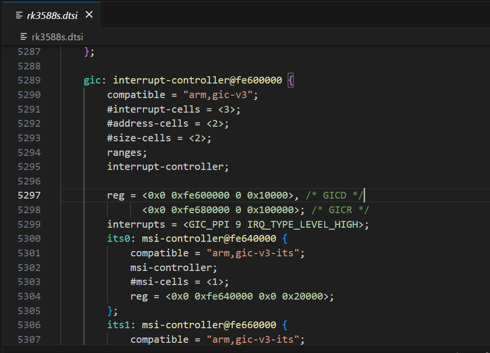
以3588的设备树为例,找到"interrupt-controller"节点,具体可以看看下面的注释部分
D
gic: interrupt-controller@fe600000 {
		compatible = "arm,gic-v3";//compatible属性用于平台设备驱动的匹配。
		#interrupt-cells = <3>;//指定使用该中断控制器的节点要用几个cells来描述一个中断
		#address-cells = <2>;
		#size-cells = <2>;
		ranges;
		interrupt-controller;//声明该设备树节点是一个中断控制器。

    //reg指定中断控制器相关寄存器的地址及大小,GICD是Distributor寄存器,GICR是指Redistributor寄存器
		reg = <0x0 0xfe600000 0 0x10000>, /* GICD */
		      <0x0 0xfe680000 0 0x100000>; /* GICR */

    //描述中断信息,这里是用三个u32描述,是前面#interrupt-cells指定的。第一个指定中断类型,第二个中断号,第三位是触发类型
		interrupts = <GIC_PPI 9 IRQ_TYPE_LEVEL_HIGH>;

    //在gic设备节点下,有一个子设备节点its,ITS设备用于将消息信号中断(MSI)路由到cpu
		its0: msi-controller@fe640000 {
			compatible = "arm,gic-v3-its";
			msi-controller;//标识该设备是MSI控制器
			#msi-cells = <1>;//必须是1,MSI设备的DeviceID
			reg = <0x0 0xfe640000 0x0 0x20000>;
		};
		its1: msi-controller@fe660000 {
			compatible = "arm,gic-v3-its";
			msi-controller;
			#msi-cells = <1>;
			reg = <0x0 0xfe660000 0x0 0x20000>;
		};
	};
具体一点:
全局
gic: interrupt-controller@fe600000 {
    ...
};
👉 这是整个 SoC 的"中断中枢"
- CPU 的所有硬件中断
- GPIO 中断
- 外设中断
- PCIe / MSI 中断
最终都会汇聚到 GIC(Generic Interrupt Controller)
节点名+label
gic: interrupt-controller@fe600000 {1️⃣ gic:(label)
-
这是一个 设备树 label
-
其他设备节点可以这样引用它:
interrupt-parent = <&gic>;
label 只是引用用的,和 Linux 设备名无关
2️⃣ interrupt-controller@fe600000
interrupt-controller:功能描述(人类看的)@fe600000:第一个寄存器地址
📌 这个地址要和 reg 里的第一个 base 对得上
compatible
Linux 是怎么知道这是 GICv3 的?通过compatible进行平台驱动匹配
#interrupt-cells ------ 中断描述格式
#interrupt-cells = <3>;一个中断需要 3 个 cell 描述,对应的格式为
interrupts = < type irq flags >;具体地
| cell | 含义 |
|---|---|
| 第 1 个 | 中断类型 |
| 第 2 个 | 中断号 |
| 第 3 个 | 触发方式 |
对于中断类型而言,是由中断类型枚举定义
| 类型 | 宏 |
|---|---|
| SPI(外设) | GIC_SPI |
| PPI(私有) | GIC_PPI |
| SGI(软件) | GIC_SGI |
#address-cells / #size-cells / ranges
#address-cells = <2>;
#size-cells = <2>;
ranges;
这是 总线属性声明
👉 表示 GIC 节点下面可以挂子设备
- 地址用 2 个 cell(64 位)
- 大小用 2 个 cell(64 位)
ranges;空表示:子地址 = 物理地址
📌 为什么要有这个?
因为下面挂了 ITS(MSI 控制器)
interrupt-controller ------ 身份声明(必须)
interrupt-controller;没有它:
- Linux 不认为这是中断控制器
interrupt-parent无法指向它
标识该节点是一个中断控制器节点
reg ------ GIC 的寄存器布局
reg = <0x0 0xfe600000 0 0x10000>, /* GICD */
      <0x0 0xfe680000 0 0x100000>; /* GICR */
首先讲讲对于这个格式
因为
#address-cells = <2>,#size-cells = <2>
所以:
地址 = 2 个 cell(高 32 位 + 低 32 位)
长度 = 2 个 cell(高 32 位 + 低 32 位)
这句话等价于告诉内核:
下面
reg里的
- 地址用 64 bit 表示
- 长度用 64 bit 表示
拆第一段 reg
<0x0 0xfe600000 0x0 0x10000>① 地址部分(2 个 cell)
0x0         0xfe600000
↑高32位     ↑低32位
拼起来就是:
地址 = (0x0 << 32) | 0xfe600000
     = 0xfe600000
👉 所以这个 0 只是"高 32 位地址"
② size 部分(2 个 cell)
0x0     0x10000
↑高32位 ↑低32位
拼起来:
size = (0x0 << 32) | 0x10000
     = 0x10000
👉 表示 64KB
等价于:
GICD 寄存器
- 起始地址:
0xfe600000- 大小:
0x10000
所以为什么不写一个cell
因为 设备树是"可移植"的 👇
- 有些 SoC:
- 地址 < 4GB →
#address-cells = 1
- 地址 < 4GB →
- 有些 SoC:
- 地址 > 4GB →
#address-cells = 2
- 地址 > 4GB →
- ARM64 平台 几乎统一用 2
所以现在看到的是 ARM64 标准写法
interrupts ------ GIC 自己也需要中断?
interrupts = <GIC_PPI 9 IRQ_TYPE_LEVEL_HIGH>;含义:
👉 GIC 的维护中断(Maintenance Interrupt)
- 类型:
PPI - 中断号:9
- 触发方式:高电平
📌 用途:
- 虚拟化
- 中断维护
- KVM / GIC 状态同步
普通外设 不会用到这个
ITS(MSI Controller)
its0: msi-controller@fe640000 {
    compatible = "arm,gic-v3-its";
    msi-controller;
    #msi-cells = <1>;
    reg = <0x0 0xfe640000 0x0 0x20000>;
};
MSI 控制器 = 管理"通过写内存触发中断"的中断控制器
它不靠中断引脚 ,而是靠 内存写事务 来触发中断。
一个GIC中断控制器的使用实例
以uart3为例(rk3568.dtsi):
c
/ {
    compatible = "rockchip,rk3568";

    interrupt-parent = <&gic>;
    #address-cells = <2>;
    #size-cells = <2>;

    /*.............*/
    uart3: serial@fe670000 {
        compatible = "rockchip,rk3568-uart", "snps,dw-apb-uart";
        reg = <0x0 0xfe670000 0x0 0x100>;
        interrupts = <GIC_SPI 119 IRQ_TYPE_LEVEL_HIGH>;
        clocks = <&cru SCLK_UART3>, <&cru PCLK_UART3>;
        clock-names = "baudclk", "apb_pclk";
        reg-shift = <2>;
        reg-io-width = <4>;
        dmas = <&dmac0 6>, <&dmac0 7>;
        pinctrl-names = "default";
        pinctrl-0 = <&uart3m0_xfer>;
        status = "disabled";
    };
    /*.............*/
};
uart3是根节点下的一个子节点,根节点指定了interrupt-parent为gic。 那么uart3子节点也继承使用GIC控制器中断控制器,并用interrupts描述了它使用的资源。
-
interrupts:具体的中断描述信息,在该节点使用的中断控制器gic,gic节点中"#interrupt-cells = <3>"规定了使用三个cells来描述子控制器的信息。 三个参数表示的含义如下:
第一个参数用于指定中断类型,在GIC的中断的类型有三种(SPI共享中断、PPI私有中断、SGI软件中断), 我们使用的外部中断均属于SPI中断类型。
第二个参数用于设定中断编号,范围和第一个参数有关。PPI中断范围是0-15,SPI中断范围是0-256。
第三个参数指定中断触发方式,参数是一个u32类型,其中后四位0-3用于设置中断触发类型。 每一位代表一个触发方式,可进行组合,系统提供了相对的宏顶义我们可以直接使用,如下所示:
中断触发方式设置(irq.h)
c++
#define IRQ_TYPE_NONE           0
#define IRQ_TYPE_EDGE_RISING    1
#define IRQ_TYPE_EDGE_FALLING   2
#define IRQ_TYPE_EDGE_BOTH      (IRQ_TYPE_EDGE_FALLING | IRQ_TYPE_EDGE_RISING)
#define IRQ_TYPE_LEVEL_HIGH     4
#define IRQ_TYPE_LEVEL_LOW 8其中第三个参数的8-15位,在PPI中断中还用于设置"CPU屏蔽"。在多核系统中这8位用于设置PPI中断发送到那个CPU,一位代表一个CPU, 为1则将PPI中断发送到CPU0,否则屏蔽。
如下示例:
c
    timer {
            compatible = "arm,armv8-timer";
            interrupts = <GIC_PPI 13 (GIC_CPU_MASK_SIMPLE(4) | IRQ_TYPE_LEVEL_HIGH)>,
                         <GIC_PPI 14 (GIC_CPU_MASK_SIMPLE(4) | IRQ_TYPE_LEVEL_HIGH)>,
                         <GIC_PPI 11 (GIC_CPU_MASK_SIMPLE(4) | IRQ_TYPE_LEVEL_HIGH)>,
                         <GIC_PPI 10 (GIC_CPU_MASK_SIMPLE(4) | IRQ_TYPE_LEVEL_HIGH)>;
            arm,no-tick-in-suspend;
    };
实验
编写一个按键中断驱动
- 编写设备树结点,引用已经写好的中断控制器父节点和配置中断信息
- 写中断驱动
设备树插件实现
注意:这边配置了一下按键引脚,以lubuncat4为例,使用40pin里面的GPIO1_B7,实际中不同板卡可能没有按键,可以替换成其他引脚,然后外接按键、或者接高低电平控制模拟按键。
c
/dts-v1/;
/plugin/;

#include <dt-bindings/gpio/gpio.h>
#include <dt-bindings/pinctrl/rockchip.h>
#include <dt-bindings/interrupt-controller/irq.h>

&{/} {
        button_interrupt: button_interrupt {
            status = "okay";
            compatible = "button_interrupt";
            button-gpios = <&gpio1 RK_PB7 GPIO_ACTIVE_LOW>;
            pinctrl-names = "default";
            pinctrl-0 = <&button_interrupt_pin>;
            interrupt-parent = <&gpio1>;
            interrupts = <RK_PB7 IRQ_TYPE_EDGE_FALLING>;
        };
    };

&{/pinctrl} {
    pinctrl_button {
        button_interrupt_pin: button_interrupt_pin {
            rockchip,pins = <1 RK_PB7 RK_FUNC_GPIO &pcfg_pull_up>;
        };
    };
};
在板卡上的部分GPIO可能会被系统占用,引脚被占用后,设备树可能无法再加载或驱动中无法再申请对应的资源, 比如运行代码时出现"Device or resource busy"或者运行代码卡死等等现象,可以注释其他的使用的设备树插件。
我们修改内核目录/arch/arm64/boot/dts/rockchip/overlays下的Makefile文件, 添加我们编辑好的设备树插件。并把设备树插件文件放在和Makefile文件同级目录下。 以进行设备树插件的编译。
在内核的根目录下执行如下命令即可:
c
# #加载配置文件
make ARCH=arm64 CROSS_COMPILE=aarch64-linux-gnu- lubancat_linux_rk3588_defconfig
#使用dtbs参数单独编译设备树
make ARCH=arm64 -j4 CROSS_COMPILE=aarch64-linux-gnu- dtbs
生成的.dtbo位于内核根目录下的"arch/arm64/boot/dts/rockchip/overlays"目录下。 本章设备树插件为"lubancat-button-overlay.dts", 编译之后就会在内核源码/arch/arm64/boot/dts/rockchip/overlays目录下生成同名的lubancat-button-overlay.dtbo文件,得到.dtbo后,下一步就是将其加载到系统中。
我们编译生成了 lubancat-button-overlay.dtbo ,该文件可以被动态的加载到系统,lubancat4板卡uboot加载设备树插件, 只需完成简单的两个步骤:
- 1、将需要加载的.dtbo文件放入板卡
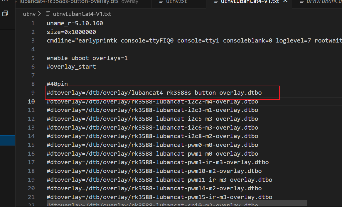
/boot/dtb/overlays/目录下。 - 2、将对应的设备树插件加载配置,写入uEnv.txt配置文件,系统启动过程中会自动从uEnv.txt读取要加载的设备树插件。打开位于"/boot/uEnv/"目录下的uEnv.txt文件,要将设备树插件写入uEnv.txt,使用sudo vim或者nano编辑器打开文件,书写格式为"dtoverlay=<设备树插件路径>"。
可以通过pc端操作,交叉编译后把板卡对应文件覆盖,也可以直接在板卡上面操作,具体不详细展开,之前的blog都讲过
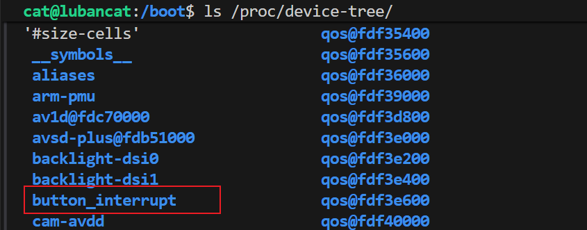
添加好后,我们重启开发板,使用命令ls /proc/device-tree/ 查看, 是否有button_interrupt目录,有就说明加载成功。
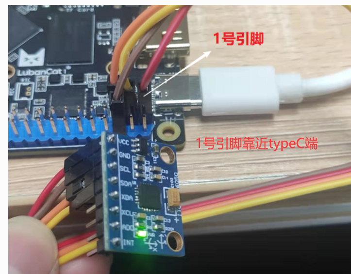
注意1号引脚的位置
驱动程序
⭐️基本上是固定的套路:
注册一个字符设备,创建结点
让内核知道:「有一个 /dev/mybutton,用户可以 open / read」
-
申请设备号
alloc_chrdev_region(&dev_num, minor, count, name); -
初始化并注册 cdev
cdev_init(&mycdev, &button_fops);
cdev_add(&mycdev, dev_num, DEVICE_NUMBER);
设备号 ↔ file_operations;用户 open 这个设备时,内核知道该调用谁
-
创建 class + device(为了 /dev)
class_create(...)
device_create(...)
自动生成
/dev/mybutton_class作用:自动生成
/dev/mybutton_class否则:你得手动mknod
硬件资源层(设备树 / GPIO / 中断)
open()
  ↓
找设备树节点
  ↓
拿 GPIO / IRQ 描述
  ↓
申请 GPIO
  ↓
配置 GPIO
  ↓
映射 IRQ
  ↓
注册中断
1️⃣ 找到硬件(设备树)2️⃣ 申请硬件资源(GPIO / IRQ)3️⃣ 把硬件"接管"给当前驱动
-
找到设备树结点
of_find_node_by_path("/button_interrupt"); -
从设备树里面拿到硬件资源
of_get_named_gpio(...);
irq_of_parse_and_map(...);
GPIO IRQ reg clock / reset
-
向内核"申请"资源
gpio_request()
request_irq() -
设置硬件的工作模式
gpio_direction_input();
中断函数(ISR)
c
static irqreturn_t button_irq_hander(int irq, void *dev_id)
{
    atomic_inc(&button_status);
    return IRQ_HANDLED;
}
关于atomic
atomic_inc() 用于在中断或并发环境下对共享变量进行安全自增, 防止普通 ++ 因中断或抢占导致的竞态条件和数据丢失
中断时随时可能发生的,它可能在:
- 用户态
read() - 内核态
copy_to_user() - 甚至另一个中断中
随时插进来执行
假设不用 atomic:
button_status = 100- 中断 A 进来,读到 100
- 还没写回
- 中断 B 又进来,也读到 100
- 两个都 +1
- 最终写回的还是 101
❌ 本来应该是 102, 中断次数直接少算
read:用户态 ↔ 内核态桥梁
button_read → atomic_read → copy_to_user释放资源
-
release
free_irq() gpio_free() -
exit------卸载模块
device_destroy
class_destroy
cdev_del
unregister_chrdev_region
应用程序
把中断的次数拿到,然后显示在屏幕上
整个程序
app.c
c
#include <stdio.h>
#include <unistd.h>
#include <fcntl.h>

int main(void)
{
    int fd;
    int button_count = 0;
    int last_count = 0;

    fd = open("/dev/mybutton", O_RDWR);
    if (fd < 0)
    {
        perror("open");
        return -1;
    }

    printf("press button...\n");

    while (1)
    {
        if (read(fd, &button_count, sizeof(button_count)) > 0)
        {
            if (button_count != last_count)
            {
                printf("button count = %d\n", button_count);
                last_count = button_count;
            }
        }
        // usleep(100 * 1000); // 100ms
    }

    close(fd);
    return 0;
}
driver.c
c
#include <linux/init.h>
#include <linux/kernel.h>
#include <linux/module.h>

#include <linux/fs.h>
#include <linux/cdev.h>
#include <linux/uaccess.h>

#include <linux/delay.h>
#include <linux/ide.h>
#include <linux/errno.h>
#include <linux/gpio.h>
#include <linux/of.h>
#include <linux/of_address.h>
#include <linux/of_gpio.h>
#include <asm/io.h>
#include <linux/device.h>
#include <linux/irq.h>
#include <linux/of_irq.h>
#include <linux/types.h>

#define DEVICE_CLASS_NAME "mybutton_class"
struct cdev mycdev;
static int major_num,minor_num;
struct class *class;

#define DEVICE_NUMBER 1
#define DEVICE_MINOR_NUMBER 0


struct device_node *button_device_node=NULL;
unsigned button_GPIO_number=0;
u32 interrupt_number=0;
atomic_t button_status=ATOMIC_INIT(0);

static irqreturn_t button_irq_hander(int irq, void *dev_id)
{
    atomic_inc(&button_status);
    printk("button irq, count=%d\n",
           atomic_read(&button_status));
    return IRQ_HANDLED;
}


static int button_open(struct inode *inode, struct file *filp)
{
    int error = -1;

    /*获取按键 设备树节点*/
    button_device_node = of_find_node_by_path("/button_interrupt");
    if(NULL == button_device_node)
    {
            printk("of_find_node_by_path error!");
            return -1;
    }

    /*获取按键使用的GPIO*/
    button_GPIO_number = of_get_named_gpio(button_device_node ,"button-gpios", 0);
    if(0 == button_GPIO_number)
    {
            printk("of_get_named_gpio error");
            return -1;
    }

    /*申请GPIO  , 记得释放*/
    error = gpio_request(button_GPIO_number, "button_gpio");
    if(error < 0)
    {
            printk("gpio_request error");
            gpio_free(button_GPIO_number);
            return -1;
    }

    error = gpio_direction_input(button_GPIO_number);

    /*获取中断号*/
    interrupt_number = irq_of_parse_and_map(button_device_node, 0);
    printk("\n irq_of_parse_and_map! =  %d \n",interrupt_number);

    /*申请中断, 记得释放*/
    error=request_irq(interrupt_number,button_irq_hander,IRQF_TRIGGER_FALLING, "button_interrupt", NULL  );

    // IRQ 号(Linux 虚拟中断)
    // 触发类型(这里从 DT 来) 因为已经在设备树里配置了触发方式(上升沿 / 下降沿 / 电平)
    // 中断名字(/proc/interrupts 可见)
    // dev_id(free_irq 要用)
    if(error != 0)
    {
        printk("request_irq error");
        free_irq(interrupt_number, NULL);
        return -1;
    }


    return 0;
}

static ssize_t button_read(struct file *filp,char __user *buf,size_t cnt,loff_t *offt)
{
    int button_counter;

    button_counter = atomic_read(&button_status);

    if (copy_to_user(buf, &button_counter, sizeof(button_counter)))
    {
        printk("copy_to_user error\n");
        return -EFAULT;
    }

    return sizeof(button_counter);
}


/*字符设备操作函数集,.release函数实现*/
static int button_release(struct inode *inode, struct file *filp)
{
	/*释放申请的引脚,和中断*/
	printk("button_release\n");
    //卸载模块前必须释放中断资源,防止中断处理函数访问已释放的内存
	free_irq(interrupt_number, NULL);
	gpio_free(button_GPIO_number);
	return 0;
}


static struct file_operations button_fops={
    .open=button_open,
    .read=button_read,
    .release=button_release
};

static int __init button_init(void){

    int ret;
    dev_t dev_num;//设备号

    printk("button_init\n");

     /*动态注册设备号*/
    ret=alloc_chrdev_region(&dev_num, DEVICE_MINOR_NUMBER, 1, "mybutton");
    if (ret < 0){
        printk("alloc_chrdev_region error\n");
    }
    printk("alloc_chrdev_region ok\n"); //动态注册设备号成功


    major_num = MAJOR(dev_num);//将主设备号取出来
    minor_num = MINOR(dev_num);//将次设备号取出来
    printk("major_num = %d\n", major_num); //打印传入进来的主设备号
    printk("minor_num = %d\n", minor_num); //打印传入进来的次设备号

    mycdev.owner=THIS_MODULE;
    cdev_init(&mycdev, &button_fops); //cdev_init 函数初始化 cdev 结构体成员变量
    cdev_add(&mycdev, dev_num, DEVICE_NUMBER);//完成字符设备注册到内核


    class = class_create(THIS_MODULE, DEVICE_CLASS_NAME);// 创建 class 类
    device_create(class,NULL,MKDEV(major_num,minor_num),NULL,"mybutton");

    return 0;
}

static void __exit button_exit(void){


    device_destroy(class, MKDEV(major_num, minor_num));//删除 /dev 节点
    class_destroy(class);//删除类
    cdev_del(&mycdev);//删除设备号
    unregister_chrdev_region(MKDEV(major_num, minor_num), DEVICE_NUMBER); //释放设备号

}

module_init(button_init);
module_exit(button_exit);
MODULE_LICENSE("GPL");
【拓】MSI Controller
对于前面的its0,这边去做了一个探究,想知道这是做什么的。
its0: msi-controller@fe640000 {
    compatible = "arm,gic-v3-its";
    msi-controller;
    #msi-cells = <1>;
    reg = <0x0 0xfe640000 0x0 0x20000>;
};
MSI控制器
MSI 控制器 = 管理"通过写内存触发中断"的中断控制器
它不靠中断引脚 ,而是靠 内存写事务 来触发中断。
传统中断(IRQ 线):外设 ------IRQ线------> GIC ------> CPU
特点:
- 一根线一个中断
- 电平 / 边沿
- 数量有限
- 容易共享、冲突
MSI(Message Signaled Interrupt):外设 ------写内存------> MSI 控制器 ------> GIC ------> CPU
👉 中断 = 一次特殊的内存写操作
写的是:
- 指定地址
- 指定数据(vector / event id)
MSI 控制器负责三件事:
- 接收设备发来的 MSI 内存写
- 解析里面的中断 ID(vector / EventID)
- 转换成 CPU 能理解的中断并投递
MSI 控制器是用于管理 Message Signaled Interrupt 的中断控制器,负责将外设通过内存写产生的 MSI 请求转换为 CPU 可识别的中断并进行分发,典型实现是在 ARM GICv3 中的 ITS 模块。
什么时候需要MSI控制器
当系统中存在 PCIe 等支持 MSI/MSI-X 的高速设备时必须要 MSI 控制器;传统 GPIO、UART 等外设不需要。
PCIe 设备
比如:
- PCIe 网卡
- NVMe SSD
- USB3 控制器
- AI / NPU / GPU
- 高速采集卡
原因:
- PCIe 协议原生支持 MSI / MSI-X
- 中断数量多(几十~几千)
- 性能要求高
没有 MSI 控制器,这些设备"跑得起来但收不到中断"
ITS
1️⃣ 什么是ITS
ITS(Interrupt Translation Service)是 ARM GICv3 中用于处理 MSI 中断的模块,负责将外设通过内存写方式产生的 MSI 事件翻译为 GIC SPI 中断,并投递给指定的 CPU。
2️⃣为什么需要ITS
因为 MSI 中断【MSI 控制器 = 管理"通过写内存触发中断"的中断控制器】不是通过物理中断线触发,GIC 本身无法直接识别,需要 ITS 进行事件 ID 到中断号的映射和翻译。
为什么非它不可
MSI 的本质是:
设备 → 写内存(Message) → 触发中断而 CPU/GIC 能理解的是:
IRQ 号 → 中断优先级 → 投递到 CPU中间差的这一步,就是 ITS 干的
ITS 在整个系统里的位置
PCIe 设备
   ↓(MSI 内存写)
ITS(中断翻译)
   ↓(SPI 中断)
GICD / GICR
   ↓
CPU
ITS 到底"翻译"了什么?
ITS 维护了几张关键映射表:
1️⃣ Device Table
- 设备 ID(PCIe BDF)
- 这个设备属于哪个 ITS
2️⃣ Event Table
- MSI Event ID
- 每个 Event 对应一个中断
3️⃣ Interrupt Translation Table(ITT)
- Event ID → GIC SPI
- Event ID → 目标 CPU
- Event ID → 优先级
👉 设备写内存时,只写一个 Event ID
👉 ITS 决定这对应哪个 IRQ
一次 MSI 中断完整发生过程
1️⃣ 系统启动
- Linux 解析 DTS
- 初始化 GIC
- 初始化 ITS
- 建立 MSI irq domain
2️⃣ PCIe 设备枚举
pci_scan_root_bus()
↓
pci_enable_msi()
↓
pci_alloc_irq_vectors()
内核此时:
- 给设备分配 Event ID
- 在 ITS 中建立映射关系
3️⃣ 设备触发中断
设备 → DMA 写 MSI 地址
      写的数据 = Event ID
4️⃣ ITS 翻译
Event ID
↓
查 ITS 表
↓
得到 SPI 中断号
↓
投递给 GIC
5️⃣ CPU 响应
GIC → CPU exception
↓
do_IRQ()
↓
驱动中断处理函数
ITS 和 GICD / GICR 的分工
| 模块 | 负责什么 |
|---|---|
| GICD | 全局 SPI 中断管理 |
| GICR | 每 CPU 的 PPI / SGI |
| ITS | MSI → SPI 的翻译 |
👉 ITS 不直接打 CPU
👉 它只是把 MSI 转成 GIC 能识别的形式
【拓】 Rockchip RK3588 芯片的技术参考手册(TRM)中关于 GIC600(通用中断控制器)的概述和配置参数表
后续更新...
这边是更多关于gic相关的内容,见手册