1. 引言
RC522是一款常用的13.56MHz非接触式读写芯片,广泛应用于门禁、考勤、智能交通等领域。它支持ISO14443A/MIFARE协议,可与M1卡、Ultralight卡等通信。这个模块我买了不少时间了,之前帮做智慧宿舍的时候有用到过,用来做卡片识别实现开门,这个模块在大学做课设毕设的时候基本都是用这个模块。
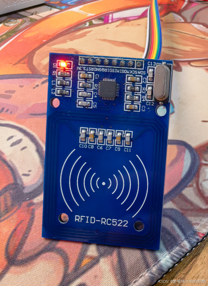
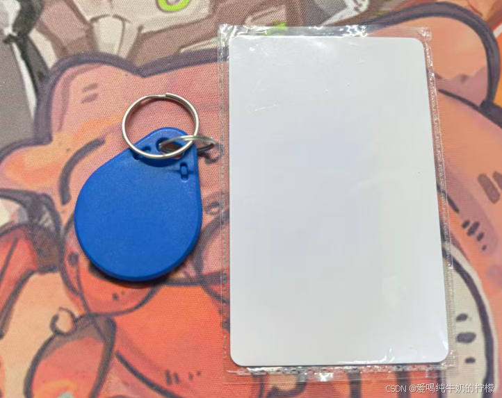
今天咱们一起来驱动这个模块,实现卡片识别,一般买这个模块都会配套送两个卡片,咱们就用这两个卡片来做测试。
2. 硬件连接
RC522模块引脚定义与STM32连接如下:
| RC522引脚 | STM32F103C8T6 | 说明 |
|---|---|---|
| SDA (NSS) | PA3 | 片选,软件控制 |
| SCK | PA5 | SPI时钟 |
| MOSI | PA7 | 主出从入 |
| MISO | PA6 | 主入从出 |
| RST | PA2 | 复位(低电平复位) |
| IRQ | 不接 | 中断输出(本例未用) |
| 3.3V | 3.3V | 供电,需稳定 |
| GND | GND | 共地 |
注意:RC522模块电流可达50mA,建议单独供电或确保3.3V稳压器输出能力足够。
3. CubeMX配置
使用STM32CubeMX生成初始化代码,关键配置如下:
-
RCC:高速外部时钟(HSE)使能,系统时钟配置为72MHz。
-
GPIO:
-
PA3(NSS)、PA2(RST)设为推挽输出。
-
PA5(SCK)、PA7(MOSI)设为推挽输出。
-
PA6(MISO)设为输入浮空。
-
-
USART1(可选):用于打印调试信息,配置为异步模式,波特率115200。
4. 驱动核心代码解析
驱动采用软件模拟SPI,便于移植。以下仅展示关键函数。
4.1 引脚宏定义(rc522_hal.h)
// 引脚定义(可根据实际连接修改)
#define RC522_CS_PORT       GPIOA
#define RC522_CS_PIN        GPIO_PIN_3
#define RC522_SCK_PORT      GPIOA
#define RC522_SCK_PIN       GPIO_PIN_5
#define RC522_MOSI_PORT     GPIOA
#define RC522_MOSI_PIN      GPIO_PIN_7
#define RC522_MISO_PORT     GPIOA
#define RC522_MISO_PIN      GPIO_PIN_6
#define RC522_RST_PORT      GPIOA
#define RC522_RST_PIN       GPIO_PIN_2

// 片选控制宏
#define RC522_CS_ENABLE()   HAL_GPIO_WritePin(RC522_CS_PORT, RC522_CS_PIN, GPIO_PIN_RESET)
#define RC522_CS_DISABLE()  HAL_GPIO_WritePin(RC522_CS_PORT, RC522_CS_PIN, GPIO_PIN_SET)

// 复位控制宏
#define RC522_RST_ENABLE()  HAL_GPIO_WritePin(RC522_RST_PORT, RC522_RST_PIN, GPIO_PIN_RESET)
#define RC522_RST_DISABLE() HAL_GPIO_WritePin(RC522_RST_PORT, RC522_RST_PIN, GPIO_PIN_SET)

// 软件SPI控制宏
#define RC522_SCK_HIGH()    HAL_GPIO_WritePin(RC522_SCK_PORT, RC522_SCK_PIN, GPIO_PIN_SET)
#define RC522_SCK_LOW()     HAL_GPIO_WritePin(RC522_SCK_PORT, RC522_SCK_PIN, GPIO_PIN_RESET)
#define RC522_MOSI_HIGH()   HAL_GPIO_WritePin(RC522_MOSI_PORT, RC522_MOSI_PIN, GPIO_PIN_SET)
#define RC522_MOSI_LOW()    HAL_GPIO_WritePin(RC522_MOSI_PORT, RC522_MOSI_PIN, GPIO_PIN_RESET)
#define RC522_MISO_READ()   HAL_GPIO_ReadPin(RC522_MISO_PORT, RC522_MISO_PIN)
4.2 微秒延时函数
软件SPI需要微秒级延时,这里使用简单的空循环实现(实际项目可根据系统时钟精确调整)。
void Delay_us(uint32_t us) {
    uint32_t i;
    for (i = 0; i < us * 8; i++) {
        __NOP();
    }
}
4.3 寄存器读写(rc522_hal.c)
通过软件SPI完成RC522寄存器的读写。
/* 写寄存器 */
static void WriteRawRC(uint8_t ucAddress, uint8_t ucValue) {
    uint8_t ucAddr = (ucAddress << 1) & 0x7E; // 写地址:最高位0
    RC522_CS_ENABLE();
    SPI_RC522_SendByte(ucAddr);
    SPI_RC522_SendByte(ucValue);
    RC522_CS_DISABLE();
}

/* 读寄存器 */
static uint8_t ReadRawRC(uint8_t ucAddress) {
    uint8_t ucAddr = ((ucAddress << 1) & 0x7E) | 0x80; // 读地址:最高位1
    uint8_t ucReturn;
    RC522_CS_ENABLE();
    SPI_RC522_SendByte(ucAddr);
    ucReturn = SPI_RC522_ReadByte();
    RC522_CS_DISABLE();
    return ucReturn;
}
4.4 RC522初始化
void RC522_Init(void) {
    RC522_GPIO_Init();          // 初始化GPIO
    RC522_RST_DISABLE();        // 释放复位
    RC522_CS_DISABLE();         // 片选无效

    PcdReset();                 // 复位RC522
    M500PcdConfigISOType('A');  // 配置ISO14443_A
}

void PcdReset(void) {
    RC522_RST_DISABLE();
    Delay_us(1);
    RC522_RST_ENABLE();
    Delay_us(1);
    RC522_RST_DISABLE();
    Delay_us(1);

    WriteRawRC(CommandReg, 0x0F);                 // 软复位
    while (ReadRawRC(CommandReg) & 0x10);         // 等待复位完成
    Delay_us(1);

    WriteRawRC(ModeReg, 0x3D);                    // 设置CRC初值0x6363
    WriteRawRC(TReloadRegL, 30);
    WriteRawRC(TReloadRegH, 0);
    WriteRawRC(TModeReg, 0x8D);
    WriteRawRC(TPrescalerReg, 0x3E);
    WriteRawRC(TxAutoReg, 0x40);                  // 调制发送信号100%ASK
}
4.5 寻卡与防冲突
/* 寻卡:获取ATQA */
char PcdRequest(uint8_t req_code, uint8_t *pTagType) {
    char cStatus;
    uint8_t ucComBuf[MAXRLEN];
    uint32_t ulLen;

    ClearBitMask(Status2Reg, 0x08);
    WriteRawRC(BitFramingReg, 0x07);
    SetBitMask(TxControlReg, 0x03);

    ucComBuf[0] = req_code;
    cStatus = PcdComMF522(PCD_TRANSCEIVE, ucComBuf, 1, ucComBuf, &ulLen);

    if ((cStatus == MI_OK) && (ulLen == 0x10)) {
        *pTagType = ucComBuf[0];
        *(pTagType + 1) = ucComBuf[1];
    } else {
        cStatus = MI_ERR;
    }
    return cStatus;
}

/* 防冲突:获取UID */
char PcdAnticoll(uint8_t *pSnr) {
    char cStatus;
    uint8_t uc, ucSnr_check = 0;
    uint8_t ucComBuf[MAXRLEN];
    uint32_t ulLen;

    ClearBitMask(Status2Reg, 0x08);
    WriteRawRC(BitFramingReg, 0x00);
    ClearBitMask(CollReg, 0x80);

    ucComBuf[0] = 0x93;
    ucComBuf[1] = 0x20;
    cStatus = PcdComMF522(PCD_TRANSCEIVE, ucComBuf, 2, ucComBuf, &ulLen);

    if (cStatus == MI_OK) {
        for (uc = 0; uc < 4; uc++) {
            *(pSnr + uc) = ucComBuf[uc];
            ucSnr_check ^= ucComBuf[uc];
        }
        if (ucSnr_check != ucComBuf[uc])
            cStatus = MI_ERR;
    }
    SetBitMask(CollReg, 0x80);
    return cStatus;
}
4.6 与卡片通信核心函数
PcdComMF522 负责发送命令并接收响应,包含超时和错误处理。
static char PcdComMF522(uint8_t ucCommand, uint8_t *pInData, uint8_t ucInLenByte,
                        uint8_t *pOutData, uint32_t *pOutLenBit) {
    char cStatus = MI_ERR;
    uint8_t ucIrqEn = 0x00;
    uint8_t ucWaitFor = 0x00;
    uint8_t ucLastBits;
    uint8_t ucN;
    uint32_t ul;

    // 根据命令配置中断使能
    switch (ucCommand) {
        case PCD_AUTHENT:
            ucIrqEn = 0x12;
            ucWaitFor = 0x10;
            break;
        case PCD_TRANSCEIVE:
            ucIrqEn = 0x77;
            ucWaitFor = 0x30;
            break;
        default:
            break;
    }

    WriteRawRC(ComIEnReg, ucIrqEn | 0x80);   // 允许中断
    ClearBitMask(ComIrqReg, 0x80);           // 清除中断标志
    WriteRawRC(CommandReg, PCD_IDLE);        // 空闲
    SetBitMask(FIFOLevelReg, 0x80);          // 清FIFO

    // 写入发送数据
    for (ul = 0; ul < ucInLenByte; ul++)
        WriteRawRC(FIFODataReg, pInData[ul]);

    WriteRawRC(CommandReg, ucCommand);
    if (ucCommand == PCD_TRANSCEIVE)
        SetBitMask(BitFramingReg, 0x80);     // 启动发送

    // 等待命令完成
    ul = 1000;
    do {
        ucN = ReadRawRC(ComIrqReg);
        ul--;
    } while ((ul != 0) && !(ucN & 0x01) && !(ucN & ucWaitFor));

    ClearBitMask(BitFramingReg, 0x80);

    if (ul != 0) {
        // 检查错误寄存器
        if (!(ReadRawRC(ErrorReg) & 0x1B)) {
            cStatus = MI_OK;
            if (ucN & ucIrqEn & 0x01)
                cStatus = MI_NOTAGERR;
            if (ucCommand == PCD_TRANSCEIVE) {
                // 读取接收数据
                ucN = ReadRawRC(FIFOLevelReg);
                ucLastBits = ReadRawRC(ControlReg) & 0x07;
                if (ucLastBits)
                    *pOutLenBit = (ucN - 1) * 8 + ucLastBits;
                else
                    *pOutLenBit = ucN * 8;
                if (ucN == 0) ucN = 1;
                if (ucN > MAXRLEN) ucN = MAXRLEN;
                for (ul = 0; ul < ucN; ul++)
                    pOutData[ul] = ReadRawRC(FIFODataReg);
            }
        } else {
            cStatus = MI_ERR;
        }
    }
    SetBitMask(ControlReg, 0x80);            // 停止定时器
    WriteRawRC(CommandReg, PCD_IDLE);
    return cStatus;
}
5. 测试例程
在main.c中实现循环读取卡片UID,并通过串口打印。
#include "rc522_hal.h"
#include <stdio.h>

int main(void) {
    HAL_Init();
    SystemClock_Config();
    MX_GPIO_Init();
    MX_USART1_UART_Init();

    RC522_Init();
    printf("RC522 Ready\r\n");

    uint8_t uid[4];
    uint8_t tagType[2];

    while (1) {
        if (PcdRequest(PICC_REQALL, tagType) == MI_OK) {
            if (PcdAnticoll(uid) == MI_OK) {
                printf("Card UID: %02X %02X %02X %02X\r\n",
                       uid[0], uid[1], uid[2], uid[3]);
                PcdSelect(uid);   // 选卡后卡片休眠
                PcdHalt();
            }
        }
        HAL_Delay(500);
    }
}
6. 常见问题与解决
| 现象 | 可能原因 | 解决方法 |
|---|---|---|
| 版本寄存器读取为0x00/0xFF | SPI通信失败 | 检查引脚连接、延时函数是否准确、电源是否稳定 |
| 寻卡失败(始终返回MI_ERR) | 天线未开启、卡片距离太远 | 确认TxControlReg低两位为1,将卡片贴近天线 |
| 读取UID偶尔成功 | 时序问题、电源噪声 | 适当增加Delay_us延时值,电源并联10μF+0.1μF电容 |
| 某些卡片(如Mifare Plus)无法读取 | 协议不兼容 | 此类卡片可能需要额外命令进入MIFARE兼容模式,或更换标准M1卡测试 |
| 认证失败(密钥错误) | 非默认密钥或扇区已被锁 | 使用正确密钥,或先测试默认密钥(0xFF×6) |
7. 测试结果
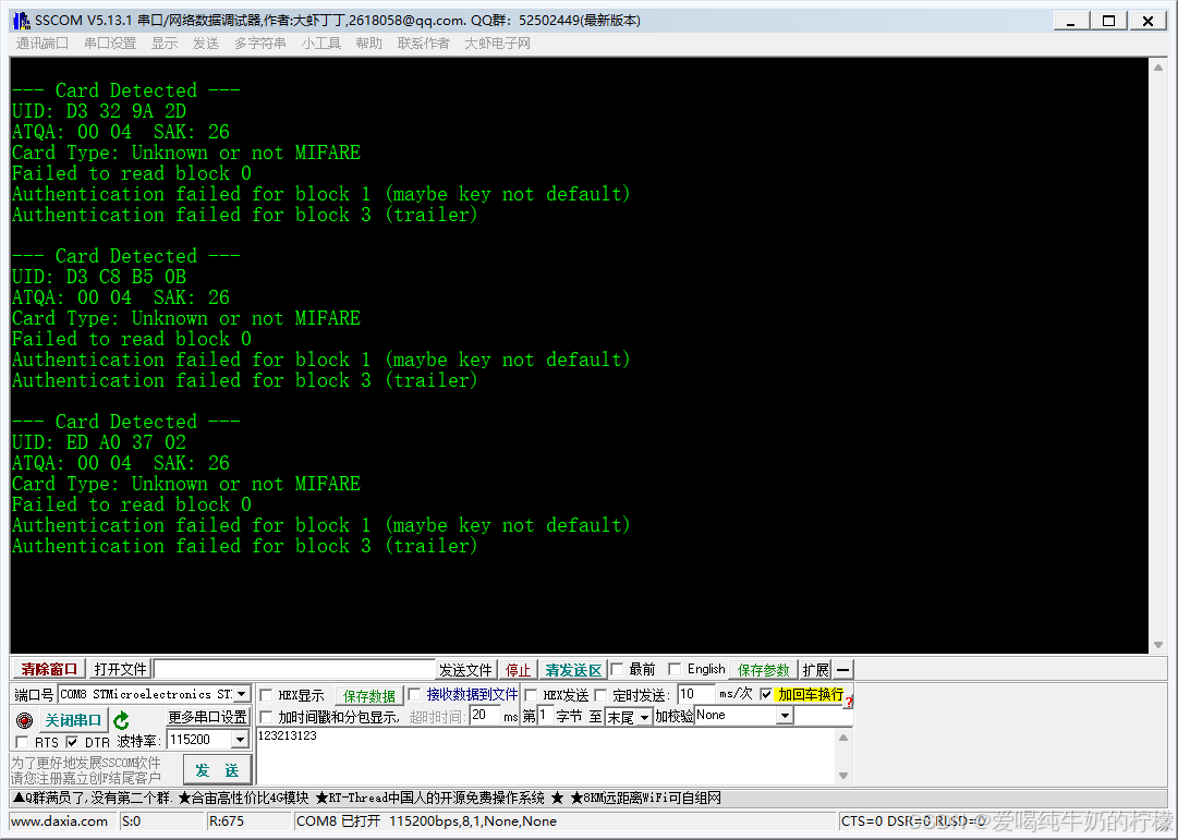
需要参考代码,请联系我哈