系列文章目录
前言
本示例展示了如何为装有手眼构型摄像头的机械臂或机械手执行和验证手眼校准。
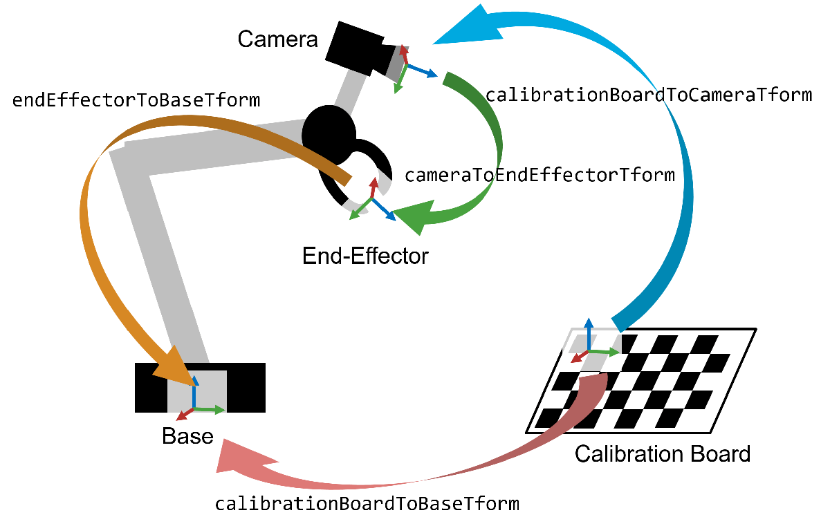
一、概述
执行手眼校准有助于操作配备末端执行器(简称 "手")的机械臂,该末端执行器依赖于摄像头提供的视觉数据。一旦完成了眼在手外的校准,机械臂就能准确地移动到摄像头识别的特定像素位置。这种能力是执行精确拾放任务(如分类、堆垛和分拣)的基础,即使在摄像机的确切位置和方向未知的情况下也是如此。
机器人-摄像机系统有两种构型:眼在手内和眼在手外。在眼在手内构型中,摄像头直接安装在机器人手臂的末端执行器上。相反,在眼在手的构型中,摄像头固定在一个静止的物体上,机器人手臂在其视野内。本示例主要针对眼在手内的构型进行手眼校准,但所述原理和技术也可适用于眼在手外的构型。
在本示例中,首先要校准摄像头,以确定其固有参数。然后进行手眼在手内校准。然后利用校准结果将图像点转换为机器人世界坐标系中的坐标。本示例需要计算机视觉工具箱和机器人系统工具箱。
二、估算相机内在参数
相机校准是眼在手内校准的第一步。这一步的重点是估算相机的固有参数(焦距、畸变等),这是消除图像畸变和估算相机相对于校准板的姿态所必需的。
要准确校准相机,请按照 "准备相机并捕捉用于相机校准的图像 "中列出的指南收集 10-20 张校准图像。在本示例中,使用 "使用单相机校准器应用程序 "以棋盘格校准模式校准了相机,并将相机参数导出到 cameraParams.mat。
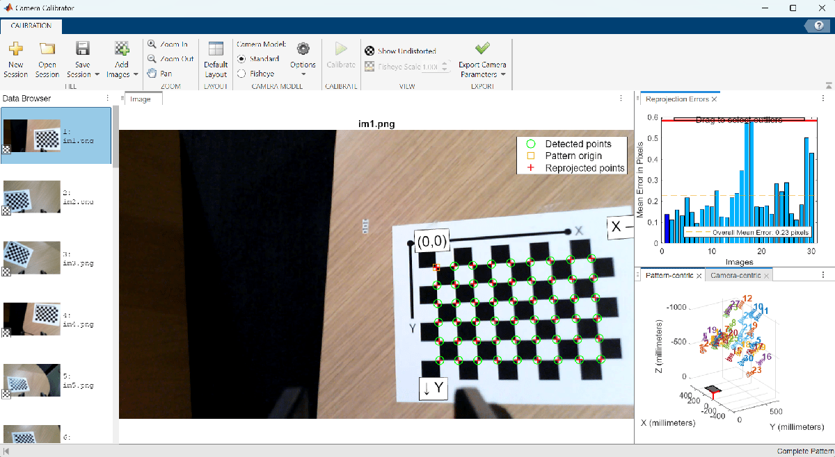
将这些估算的摄像机固有参数加载到 MATLAB 中。
Matlab
ld = load("cameraParams.mat");
intrinsics = ld.cameraParams.Intrinsics;
三、收集用于手眼校准的图像
为进行手眼校准,您必须从不同角度拍摄 15-30 张照片。应确保机器人姿势集涵盖机器人机械手工作空间的广泛范围。利用这些图像和摄像头的固有参数,可以确定校准板和摄像头之间的变换。
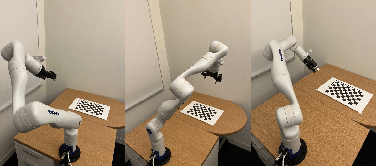
在整个过程中,必须确保校准板在摄像机的视野内完全可见。为了优化精确度,在摄像头校准过程中,要捕捉一组与眼在手内校准不同的图像。每个姿势都要保存一张摄像头图像和机器人关节角度。本示例使用的是 KINOVA Gen3 机械臂,其末端执行器附近安装有摄像头。用于 KINOVA Gen3 机械手的机器人系统工具箱支持包除了提供控制机械臂运动的功能外,还包括用于收集摄像头图像及其相应姿势角度的工具。将摄像头图像加载到 MATLAB 中的图像数据库中。
Matlab
numPoses = 30;
imds = imageDatastore("calibrationData");
montage(imds)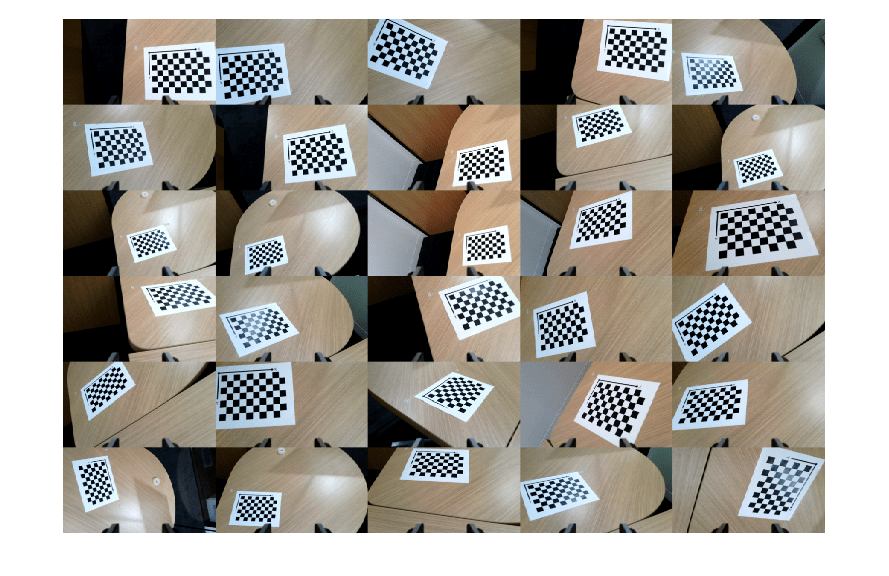
四、估算摄像机外在参数
在此步骤中,您需要估算摄像机的外特征参数,包括确定每个姿态下从校准板原点到摄像机的变换。外特征参数估算过程可确定未扭曲图像中校准棋盘点的位置。然后利用这些点确定摄像机相对于校准板的位置和方向。有关摄像机外差估计过程的详细信息,请参阅 estimateExtrinsics。
Matlab
squareSize = 0.022; % Measured in meters
camExtrinsics(numPoses,1) = rigidtform3d;

% Estimate transform from the board to the camera for each pose.
for i = 1:numPoses

    % Undistort the image using the estimated camera intrinsics.
    calibrationImage = readimage(imds,i);
    undistortedImage = undistortImage(calibrationImage,intrinsics);

    % Estimate the extrinsics while disabling the partial checkerboard
    % detections to ensure consistent checkerboard origin across poses.
    [imagePoints, boardSize] = detectCheckerboardPoints(undistortedImage,PartialDetections=false);
    worldPoints = patternWorldPoints("checkerboard",boardSize,squareSize);
    camExtrinsics(i) = estimateExtrinsics(imagePoints,worldPoints,intrinsics);
end
五、计算机器人末端执行器到基座的变换
在这一步中,您将使用之前收集的机器人姿势,计算每个姿势下机器人末端执行器关节到基座的变换。将姿势数据载入 MATLAB。
Matlab
jointConfiguration = load("calibrationData/jntconfig.mat");
jointPositionsDeg = jointConfiguration.jointPositions;
使用 loadrobot 加载 Kinova Gen3 机器人的刚体树模型。支持的机器人列表请点击此处。
Matlab
robotModel = loadrobot("kinovaGen3");
robotModel.DataFormat = "column";
针对每个校准姿势,计算从机器人末端执行器关节到基座的 4×4 变换。这些变换中的距离以米为单位。
Matlab
endEffectorToBaseTform(numPoses,1) = rigidtform3d;
for i = 1:numPoses
    jointPositionsRad = deg2rad(jointPositionsDeg(i,:))'; % Convert the pose angles from degrees to radians.
    endEffectorToBaseTform(i) = getTransform(robotModel,jointPositionsRad,"EndEffector_Link");
end
六、估算摄像机到末端执行器的变换
使用 helperEstimateHandEyeTransform 函数估算 "眼在手内 "构型的摄像机到末端执行器的变换。要使用 "眼在手外 "构型,请参阅 "估算固定摄像机相对于机器人底座的姿态(机器人系统工具箱)"示例。
Matlab
config = "eye-in-hand";
cameraToEndEffectorTform = helperEstimateHandEyeTransform(camExtrinsics,endEffectorToBaseTform,config)
Matlab
cameraToEndEffectorTform =
  rigidtform3d with properties:

    Dimensionality: 3
       Translation: [-0.0079 0.0475 0.0075]
                 R: [3×3 double]

                 A: [-0.9953    0.0949   -0.0168   -0.0079
                     -0.0951   -0.9954    0.0141    0.0475
                     -0.0154    0.0156    0.9998    0.0075
                           0         0         0    1.0000]
辅助函数会返回一个 rigidtform3d 对象,其中包含从摄像机到末端执行器关节的变换,可用于计算摄像机到机器人基座的变换。
七、通过执行物体拾取验证校准
通过指示机器人拾取摄像头视野内检测到的物体,来验证已校准的系统。本示例使用附在立方体上的 AprilTag 演示验证过程。AprilTags 是一种靶标,有助于对摄像头进行精确的外部估计,从而使机器人能够接近并拾取立方体。
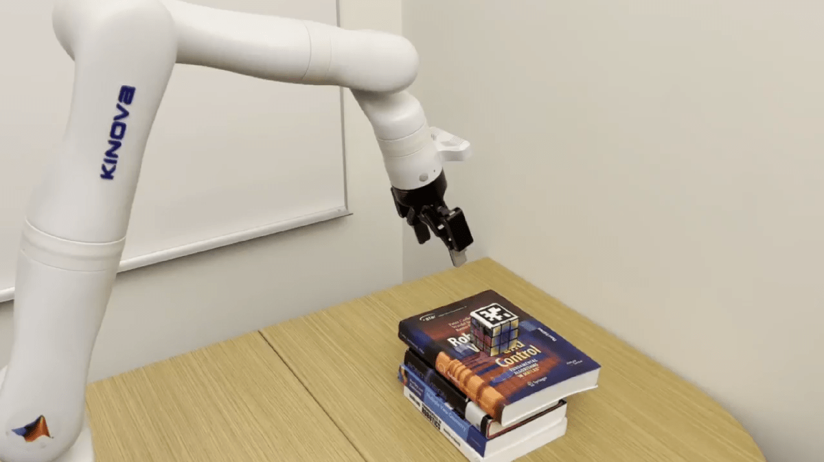
首先定位机器人手臂,使 AprilTag 位于摄像头的视野内。然后,捕捉图像并记录机器人的当前姿势,包括关节角度。
Matlab
% Load the test pose angles.
load("testData/poses.mat");
testPose = pose_angles';

% Load and undistort the test image.
testImage = imread("testData/im1.png");
undistortedTestImage = undistortImage(testImage,ld.cameraParams);

% Compute the end-effector joint to base transformation for the test pose.
testPoseRad = deg2rad(testPose);
endEffectorToBaseTformTest = getTransform(robotModel,testPoseRad,"EndEffector_Link");
使用 readAprilTag 函数计算从 AprilTag 到相机的转换。
Matlab
% Specify the tag family and tag size of the AprilTag.
tagFamily = 'tag36h11';
tagSize = .049; % AprilTag size in meters

% Detect AprilTag in test image.
[~,~,aprilTagToCameraTform] = readAprilTag(undistortedTestImage,tagFamily,intrinsics,tagSize);
现在,将变换相乘,以确定 AprilTag 相对于机器人底座的变换。
Matlab
% Find the transformation from the robot base to the camera.
cameraToBaseTestTform = rigidtform3d(endEffectorToBaseTformTest * cameraToEndEffectorTform.A);

% Find the transformation from the robot base to the April Tag.
tagToBaseTestTform = cameraToBaseTestTform.A * aprilTagToCameraTform.A;
cubePosition = tagToBaseTestTform(1:3,4)
Matlab
cubePosition = 3×1

    0.6936
   -0.0042
    0.1760
AprilTag 的位置在机器人前方 0.69 米、左侧 0.004 米和底座上方 0.176 米处。
为了验证计算的准确性,请绘制一张显示机器人、摄像头和立方体位置的曲线图。然后可以将直观图与初始测试设置进行比较。
Matlab
% Show the 3D Robot model, with the base at the origin.
show(robotModel,testPoseRad);
hold on

% Show the estimated positions and orientations of the camera and cube.
plotCamera(AbsolutePose = cameraToBaseTestTform, Opacity=0, size=0.02)
scatter3(cubePosition(1), cubePosition(2), cubePosition(3), 300, 'square', 'filled')
cubeRotationQuaternion = rotm2quat(tagToBaseTestTform(1:3,1:3));
plotTransforms(cubePosition', cubeRotationQuaternion)
title("Robot Arm and Estimated Position of AprilTag Cube")
xlim([-.3,.9])
ylim([-.5, .5])
zlim([-.2,.9])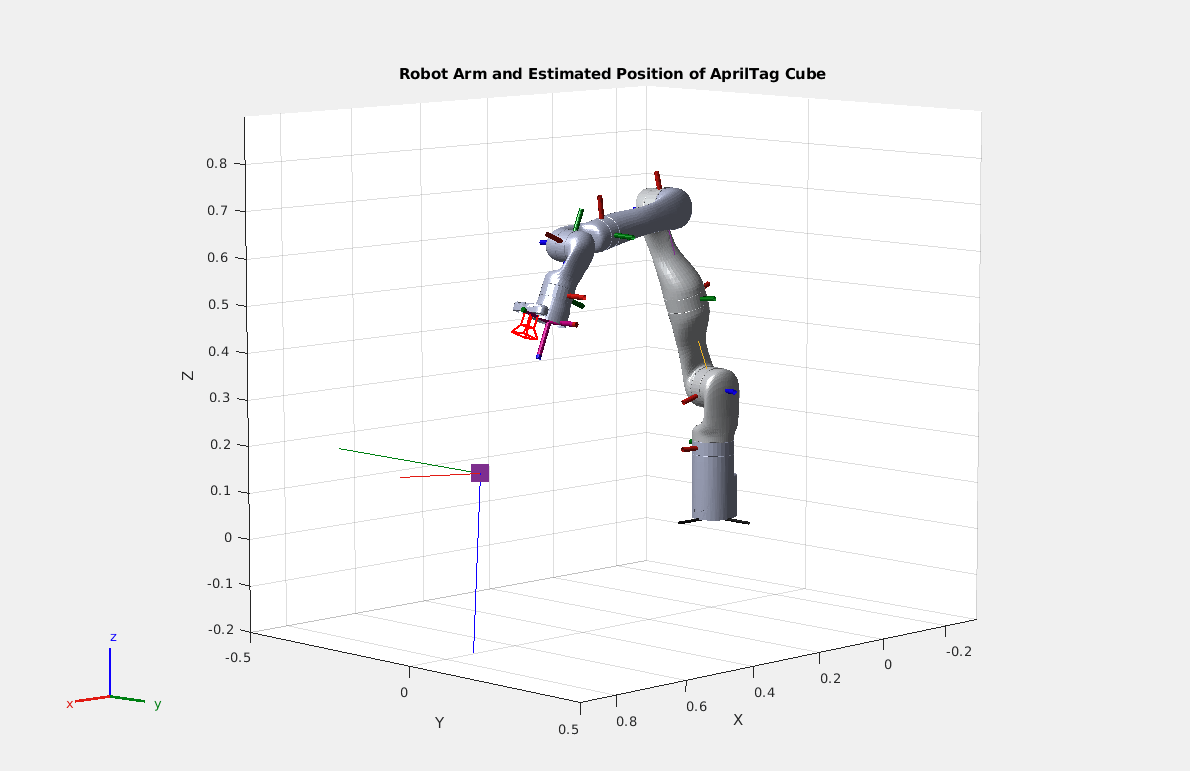
鉴于摄像头和立方体的绘图标记大致处于正确的位置和方向,将立方体的坐标传递给机器人,并命令它将末端执行器关节移动到正确的位置。机器人系统工具箱和 ROS 工具箱提供的函数可以计算将末端执行器关节移动到位置所需的电机输入,并将这些控制发送给机器人。机器人系统工具箱中的逆运动学(inverseKinematics)函数提供了一个求解器,用于找到一组关节角度,以完成末端执行器关节相对于机器人基座的定位和旋转。
在下面的视频中,机器人通过手眼在手外校准计算出立方体的位置,并将其抓手移动到立方体的坐标位置将其抓起。

八、结论
在本示例中,机器人的眼在手内校准促进了精确的拾放操作,使机械臂能够定位摄像头视野中的物体,并将该位置转换到机器人的坐标系中。在相机的精确位置未知或难以测量的情况下,手眼校准对于将相机集成到机械臂系统中非常有用。
九、辅助函数
HelperEstimateHandEyeTransform 函数遵循 Tsai 和 Lenz [1] 的算法,用于估算从末端执行器关节到摄像头的变换。
Matlab
function cameraToEndEffectorTform = helperEstimateHandEyeTransform(boardToCameraTform, endEffectorToBaseTform, configuration)
    arguments
        boardToCameraTform (:,1) rigidtform3d
        endEffectorToBaseTform (:,1) rigidtform3d
        configuration {mustBeMember(configuration, ["eye-in-hand","eye-to-hand"])}
    end
    numPoses = size(boardToCameraTform,1);

    % In the eye-to-hand case, the camera is mounted in the environment and
    % the calibration board is mounted to the robot end-effector joint.
    if configuration == "eye-to-hand"
        for i = 1:numPoses
            currAInv = boardToCameraTform(i).invert().A;
            endEffectorToBaseTform(i) = rigidtform3d(currAInv);
        end
    end

    % Reorder the poses to have greater angles between each pair.
    orderOfPoses = helperOptimalPoseOrder(boardToCameraTform);
    boardToCameraTform(:,:,:) = boardToCameraTform(:,:,orderOfPoses);
    endEffectorToBaseTform(:,:,:) = endEffectorToBaseTform(:,:,orderOfPoses);

    PEndEffectorIToJ=repmat(zeros(3,1), 1, 1, numPoses-1);
    PCameraIToJ=PEndEffectorIToJ;

    % Iterate through pairs of poses to determine transformation angle.
    for i = 1:numPoses-1
        j=i+1;

        % Collect the 4 transforms of interest.
        TCameraI = boardToCameraTform(i).A;
        TCameraJ = boardToCameraTform(j).A;
        TEndEffectorI = endEffectorToBaseTform(i).A;
        TEndEffectorJ = endEffectorToBaseTform(j).A;

        % Get transforms grom end-effector joint I to end-effector joint J, and for camera I and
        % camera J.
        TEndEffectorIJ = TEndEffectorJ\TEndEffectorI;
        TCameraIJ = (TCameraI'\TCameraJ')';

        % Get the axes and angles of the for both transforms.
        axangCIJ = tform2axang(TCameraIJ);
        axangGIJ = tform2axang(TEndEffectorIJ);
        thetaCIJ = axangCIJ(4);
        thetaGIJ = axangGIJ(4);
        PCameraIToJax = axangCIJ(1:3);
        PEndEffectorIToJax = axangGIJ(1:3);

        % P vectors contain the axis of rotation and are scaled to represent
        % the amount of rotation using Rodrigues' rotation formula.
        PCameraIToJ(:,:,i) = 2*sin(thetaCIJ/2)*PCameraIToJax';
        PEndEffectorIToJ(:,:,i) = 2*sin(thetaGIJ/2)*PEndEffectorIToJax';
    end

    % Set up least squares problem for rotation estimation.
    A=zeros((numPoses-1)*3,3);
    b=zeros((numPoses-1)*3,1);
    for i = 1:numPoses-1
        A((i-1)*3+1:i*3,:) = helperSkewMatrix(PEndEffectorIToJ(:,:,i) + PCameraIToJ(:,:,i));
        b((i-1)*3+1:i*3,1) = PCameraIToJ(:,:,i) - PEndEffectorIToJ(:,:,i);
    end
    [PEndEffectorToCameraUnscaled,~] = lsqr(A,b);
    PEndEffectorToCameraScaled = (2 * PEndEffectorToCameraUnscaled) / sqrt(1 + norm(PEndEffectorToCameraUnscaled)^2);

    % Find rotation given in Tsai, Lenz Equation 10.
    PSkew = helperSkewMatrix(PEndEffectorToCameraScaled);
    REndEffectorToCamera = (1 - (0.5 * norm(PEndEffectorToCameraScaled)^2)) * eye(3) + 0.5 * (PEndEffectorToCameraScaled * ...
        PEndEffectorToCameraScaled' + sqrt(4 - norm(PEndEffectorToCameraScaled)^2) * PSkew);

    % Clear A and b.
    A(:,:) = 0;
    b(:,:) = 0;

    % Iterate through numPoses-1 pairs of poses to find the translation part
    % of the transformation.
    for i = 1:numPoses-1
        j = i+1;

        % Use known transforms to compute transforms between poses.
        TCameraI = boardToCameraTform(i).A;
        TCameraJ = boardToCameraTform(j).A;
        TEndEffectorI = endEffectorToBaseTform(i).A;
        TEndEffectorJ = endEffectorToBaseTform(j).A;
        TEndEffectorIJ = TEndEffectorJ \ TEndEffectorI;
        TCameraIJ = (TCameraI' \ TCameraJ')';

        % Set up least squares to estimate translation.
        A((i-1)*3+1:i*3,:) = TEndEffectorIJ(1:3,1:3)-eye(3);
        b((i-1)*3+1:i*3,1) = REndEffectorToCamera*TCameraIJ(1:3,4)-TEndEffectorIJ(1:3,4);
    end

    % Compute translation using least squares.
    [TranslationEndEffectorToCamera,~] = lsqr(A,b);
    TEndEffectorToCamera = trvec2tform(TranslationEndEffectorToCamera')*rotm2tform(REndEffectorToCamera);
    cameraToEndEffectorTform = rigidtform3d(TEndEffectorToCamera);
end
helperSkewMatrix 函数从 3d 向量创建一个 3x3 倾斜对称矩阵,用于 helperEstimateHandEyeTransform。
Matlab
function skew = helperSkewMatrix(v)
    skew = [0,-v(3), v(2) ;
            v(3), 0 , -v(1);
           -v(2), v(1), 0];
end
辅助最优姿势排序(helperOptimalPoseOrder)函数给出了机器人手臂姿势的贪婪最优排序,使每对连续姿势之间的相机位置角度差达到最大,而不会重复使用姿势。事实证明,增加每对姿势之间的角度可以提高 Tsai 和 Lenz 算法的精确度 [1]。
Matlab
function orderOfPoses = helperOptimalPoseOrder(TCameraToBoard)
    % Create necessary vectors.
    numPoses = size(TCameraToBoard,3);
    anglesBetween = ones(numPoses-1,1);
    orderOfPoses = 1:numPoses;

    % Iterate over the indices to choose each subsequent pose.
    for i = 1:numPoses-2
        TCameraI = TCameraToBoard(:,:,i);

        % Collect the angles between pose i and the remaining poses.
        for j = i+1:numPoses
            TCameraJ = TCameraToBoard(:,:,j);
            TCameraIJ = TCameraI \ TCameraJ;
            axangcij = tform2axang(TCameraIJ);
            anglesBetween(j) = axangcij(4);
        end

        % Select the pose with the maximum angle to appear next in the
        % ordering.
        [~, idMax] = max(anglesBetween(i:end));
        tmp = orderOfPoses(i+1);
        orderOfPoses(i+1) = orderOfPoses(idMax+i-1);
        orderOfPoses(idMax+i-1) = tmp;
    end
end
References
1\] Tsai, R.Y. and Lenz, R.K., 1989. A new technique for fully autonomous and efficient 3d robotics hand/eye calibration. *IEEE Transactions on robotics and automation* , *5*(3), pp.345-358.